Jet JTS-700S Bedienungsanleitung
Inhaltsverzeichnis
Verfügbare Sprachen
Verfügbare Sprachen
GB - ENGLISH
Operating Instructions
Dear Customer,
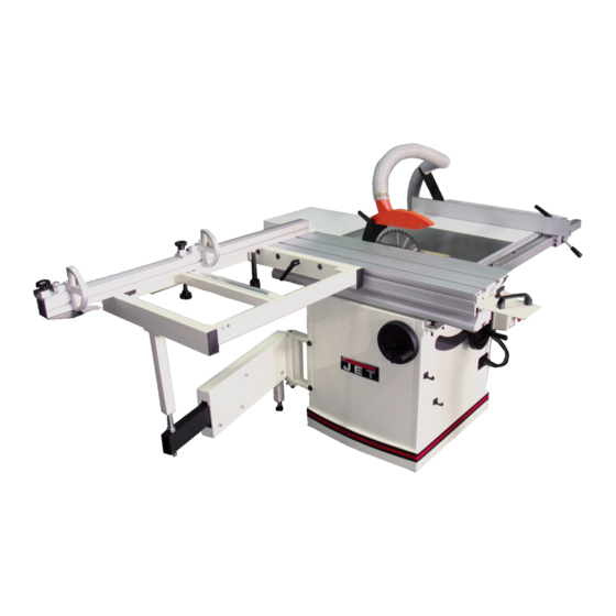
Many thanks for the confidence you have shown in us with the purchase of your new JET-machine. This manual has been
prepared for the owner and operators of a JET JTS-700S/700L table saw to promote safety during installation, operation and
maintenance procedures. Please read and understand the information contained in these operating instructions and the
accompanying documents. To obtain maximum life and efficiency from your machine, and to use the machine safely, read this
manual thoroughly and follow instructions carefully.
...Table of Contents
1. Declaration of conformity
2. Warranty
3. Safety
Authorized use
General safety notes
Remaining hazards
4. Machine specifications
Technical data
Noise emission
Dust emission
Contents of delivery
5. Transport and start up
Transport and installation
Assembly
Dust connection
Mains connection
Starting operation
6. Machine operation
7. Setup and adjustments
Changing saw blade
Mounting the raving knife
Mounting the saw guard
Rising and tilting saw blade
Sliding table setup
Rip fence setup
8. Maintenance and inspection
9. Troubleshooting
10. Environmental protection
11. Available accessories
12. „Safe operation"........ appendix A
1. Declaration of conformity
On our own responsibility we hereby
declare that this product complies with
the regulations* listed on page 2.
Designed in consideration with the
standards**. CE type examination***
conducted by****.
2. Warranty
The Seller guarantees that the
supplied product is free from material
defects and manufacturing faults. This
warranty does not cover any defects
which are caused, either directly or
indirectly, by incorrect use,
carelessness, accidental damage,
repair, inadequate maintenance or
cleaning and normal wear and tear.
Guarantee and/or warranty claims
must be made within twelve months
from the date of purchase (date of
invoice). Any further claims shall be
excluded.
This warranty includes all guarantee
obligations of the Seller and replaces
all previous declarations and
agreements concerning warranties.
The warranty period is valid for eight
hours of daily use. If this is exceeded,
the warranty period shall be reduced
in proportion to the excess use, but to
no less than three months.
Returning rejected goods requires the
prior express consent of the Seller and
is at the Buyer's risk and expense.
Further warranty details can be found
in the General Terms and Conditions
(GTC). The GTC can be viewed at
www.jettools.com or can be sent by
post upon request.
The Seller reserves the right to make
changes to the product and
accessories at any time.
3. Safety
3.1 Authorized use
3
This machine is designed for sawing
wood, wood derived materials as well
as similar to be machined hard
plastics only.
Machining of other materials is not
permitted and may be carried out in
specific cases only after consulting
with the manufacturer.
No metal workpieces may be
machined.
No cuts without using the rip fence,
the 90° fence or the sliding table may
be performed.
No submerged cuts by removing the
riving knife and/or saw guard may be
performed.
The use of a power feeder is not
considered.
The proper use also includes
compliance with the operating and
maintenance instructions given in this
manual.
The machine must be operated only
by persons familiar with its operation,
maintenance and repair and who are
familiar with its hazards.
The required minimum age must be
observed.
The machine must only be used in a
technically perfect condition.
When working on the machine, all
safety mechanisms and covers must
be mounted.
In addition to the safety requirements
contained in this operating instruction
and your country's applicable
regulations, you should observe the
generally recognized technical rules
concerning the operation of
woodworking machines.
Any other use exceeds authorization.
In the event of unauthorized use of the
machine, the manufacturer renounces
all liability and the responsibility is
transferred exclusively to the operator.
Kapitel
Inhaltsverzeichnis

Verwandte Anleitungen für Jet JTS-700S


Inhaltszusammenfassung für Jet JTS-700S
-
Seite 10: Inhaltsverzeichnis
Gebrauchsanleitung Sehr geehrter Kunde, vielen Dank für das Vertrauen, welches Sie uns beim Kauf Ihrer neuen JET-Maschine entgegengebracht haben. Diese Anleitung ist für den Inhaber und die Bediener zum Zweck einer sicheren Inbetriebnahme, Bedienung und Wartung der Formatkreissäge JTS-700S/700L erstellt worden. Beachten Sie bitte die Informationen dieser Gebrauchsanleitung und der beiliegenden Dokumente. -
Seite 11: Allgemeine Sicherheitshinweise
Neben den in der Gebrauchsanleitung Die Maschine so aufstellen, dass Beim Arbeiten an der Maschine keine enthaltenen Sicherheitshinweisen und genügend Platz zum Bedienen und Handschuhe tragen. den besonderen Vorschriften Ihres zum Führen der Werkstücke gegeben Zum Handhaben des Sägeblattes Landes sind die für den Betrieb von ist. - Seite 12 Eine geeignete Absauganlage Netzanschluss 230V ~1/N/PE 50Hz einsetzen! Abgabeleistung 2,2kW (3 PS) S1 4.3 Staubemission Die Type und der Zustand des Betriebsstrom 13 A Sägeblattes sind für einen niedrigen Die Tischkreissäge JTS-700S/700L Anschlussleitung (H07RN-F): Lärmpegel wichtig. wurde staubemmissionsgeprüft. 3x1,5mm² Bauseitige Absicherung...
-
Seite 13: Lieferumfang
Bei 20 m/s Luftgeschwindigkeit am Zum Transport verwenden Sie einen Entfernen Sie die rot lackierte Motor- Absaugstutzen Durchmesser 100mm: handelsüblichen Stapler oder Transportsicherung (2). Hubwagen. Sichern Sie die Maschine Unterdruck 850 Pa Den Maschinen-Gehäusedeckel beim Transport gegen Umfallen. Volumenstrom 565 m³/h wieder festschrauben. - Seite 14 Positionieren Sie den Schiebetisch so, Fig 9 dass der Schlittenhub auf der Mitte Setzen Sie den Gehrungsanschlag auf des Sägeblattes stoppt (Fig 7). den Schiebetisch. Setzen Sie die Anschlagleiste (E) auf den Gehrungsanschlag und befestigen Sie mit Hülsen (F) und Klemmgriffen (H).
-
Seite 15: Absaug Anschluss
Verwenden Sie nur Anschlussleitungen mit Kennzeichnung H07RN-F. Anschlüsse und Reparaturen der elektrischen Ausrüstung dürfen nur von einer Elektrofachkraft durchgeführt werden. Die Maschine ist an der Rückseite mit einer 16A CCE Steckdose versehen. Achtung: Prüfen Sie zuerst die Spindel- Drehrichtung (Uhrzeigersinn ist korrekt). -
Seite 16: Rüst- Und Einstellarbeiten
Beim Sägen von unhandlichen Das Sägeblatt muss den angegeben Montieren Sie das Sägeblatt auf der Werkstücken geeignete Hilfsmittel technischen Daten entsprechen. Sägewelle. Versichern Sie sich dass zum Abstützen verwenden. die Zähne des Sägeblattes in Verwenden Sie nur Sägeblätter, die Schnittrichtung (vorne nach unten) Es ist darauf zu achten dass alle EN 847-1 entsprechen. -
Seite 17: Montage Der Sägeschutzhaube
Der Parallelanschlag ist ab Werk Absauganlage anzuschließen. parallel zum Sägeblatt eingestellt. Das Motor-Lüfterrad entfernen. Die verschlissene Bremseinheit 7.4 Sägeblatt Einstellung ersetzen ( Jet Teilenummer: 8. Wartung und Inspektion AB200702) Einstellung nie bei laufender Maschine Allgemeine Hinweise: vornehmen. Lüfterrad, Lüfterhaube und Vor Wartungs- Reinigungs- und Gehäusedeckel wieder anbringen. -
Seite 18: Störungsabhilfe
Anschlag *Anschlag nicht parallel zu Tischnut- Anschlag prüfen und einstellen. *Werkstück krumm oder verdreht- Fig 18 wählen Sie ein anderes Werkstück. Siehe die JET-Preisliste. Werkstückrückschlag *Anschlag nicht parallel zu Sägeblatt- Anschlag prüfen und einstellen. 12. Sicheres Arbeiten *Spaltkeil nicht montiert-...