SICK LFP Inox Bedienungsanleitung
Quicklinks
Australia
New Zealand
Phone
+61 3 9457 0600
Phone
+64 9 415 0459
1800 334 802 – tollfree
0800 222 278 – tollfree
Phone +1(952) 941-6780
Austria
1 800-325-7425 – tollfree
Phone
+43 (0)22 36 62 28 8-0
Norway
Belgium/Luxembourg
Phone
+47 67 81 50 00
Phone
+32 (0)2 466 55 66
Poland
Brazil
Phone
+48 22 837 40 50
Phone
+55 11 3215-4900
Romania
Canada
Phone
+40 356 171 120
Phone
+1 905 771 14 44
Russia
Czech Republic
Phone
+7-495-775-05-30
Phone
+420 2 57 91 18 50
Singapore
Chile
Phone
+65 6744 3732
Phone
+56 2 2274 7430
Slovakia
China
Phone
+421 482 901201
Phone
+86 4000 121 000
Slovenia
Denmark
Phone
+386 (0)1-47 69 990
Phone
+45 45 82 64 00
SICK AG • Fluid Sensors
South Africa
Finland
Erwin-Sick-Straße 1
Phone
+27 11 472 3733
Phone
+358-9-2515 800
D-79183 Waldkirch • www.sick.com
South Korea
France
Phone
+82 2 786 6321
Phone
+33 1 64 62 35 00
8018147/ZNR0/2017-07-17
Spain
Gemany
Printed in Germany (2017-07)
Phone
+34 93 480 31 00
Phone
+49 211 5301-301
All rights reserved
Sweden
Great Britain
Phone
+46 10 110 10 00
Subject to change without notice
Phone
+44 (0)1727 831121
Switzerland
Hong Kong
Phone
+41 41 619 29 39
Phone
+852 2153 6300
Taiwan
Hungary
Phone
+886 2 2375-6288
Phone
+36 1 371 2680
Thailand
India
Phone
+66 2645 0009
Phone
+91–22–4033 8333
Turkey
Israel
Phone
+90 (216) 528 50 00
Phone
+972-4-6881000
United Arab Emirates
Italy
Phone
+971 (0) 4 88 65 878
Phone
+39 02 27 43 41
USA/Mexico
Japan
Phone
+1(952) 941-6780
Phone
+81 (0)3 5309 2112
- www.sick.com/LFP_Inox
1 (800) 325-7425 – tollfree
Malaysia
Vietnam
Phone
+603 808070425
Phone
+84 8 62920204
Netherlands
Phone
+31 (0)30 229 25 44
DEUTSCH
Dieses Dokument gilt nur in Verbindungmit der zugrunde
This document is only valid in conjunction with the origi-
liegenden Betriebsanleitung (SICK Art-Nr. 8014485) des
nal operating instructions (SICK part no. 8014485) for
verwendeten LFP Inox. Die Betriebsanleitung können Sie
the corresponding LFP Inox. You can obtain the operating
unter www.sick.com herunterladen.
instructions at www.sick.com.
Sicherheitshinweise
Safety Notes
Lesen Sie die Betriebsanleitung vor der Inbetriebnah-
Read the operating instructions prior to commission-
■
■
me.
ing.
■
Dieser Quickstart gilt für Geräte ab Firmwareversion
■
This quickstart applies to devices with firmware
V4.00.
version V4.00.
■
Anschluss, Montage und Einstellung nur durch
■
Connection, mounting, and setting may only be
Fachpersonal.
performed by trained specialists.
Der LFP ist kein Sicherheitsmodul gemäß EU-Maschi-
The LFP is not a safety module according to the EU
■
■
nenrichtlinie.
Machinery Directive.
Beachten Sie die nationalen Sicherheits- und Unfall-
Observe national safety and work safety regulations.
■
■
verhütungsvorschriften.
Repairs may only be carried out by the manufacturer.
■
■
Reparaturen dürfen nur vom Hersteller durchgeführt
Altering or tampering with the device is not permitted.
werden. Eingriffe und Änderungen am Gerät sind
Wiring work and the opening and closing of electrical
■
unzulässig.
connections may only be carried out when the power
Verdrahtungsarbeiten, Öffnen und Schließen von
is switched off.
■
elektrischen Verbindungen nur im spannungs losen
The radiated power is far lower than that from
■
Zustand durchführen.
telecommunication equipment. According to current
Die abgestrahlte Energie unterschreitet die von
scientific knowledge, operating the device is not
■
Telekommunikationseinrichtungen um ein Viel faches.
considered to pose any health risks.
Nach dem aktuellen Stand der Wissenschaft kann der
■
Incorrect handling or improper use can lead to
Betrieb des Gerätes als gesundheitlich unbedenklich
malfunctions in your application.
eingestuft werden.
Unsachgemäßer oder nicht bestimmungsgemäßer
■
Gebrauch können zu Funkitonsstörungen in Ihrer
Applikation führen.
Wartung/Rücksendung/Entsorgung
Maintenance/Returns/Disposal
Der LFP ist wartungsfrei. Wir empfehlen in regelmäßigen
The LFP is maintenance-free. We recommend doing the
Abständen:
following regularly:
■
die Sonde auf Verschmutzung zu überprüfen
■
checking the probe for contamination
die Verschraubungen und Steckverbindungen zu
checking the screw connections and plug-in connec-
■
■
überprüfen
tions
Unbedenklichkeitserklärung (Kontaminationserklärung
Declaration of no objection (contamination declaration
im Servicefall)
in the event of service work)
Spülen bzw. säubern Sie ausgebaute Geräte vor der
Rinse off or clean removed devices before returning
Rücksendung, um unsere Mitarbeiter und die Umwelt
them in order to protect our employees and the environ-
vor Gefährdung durch anhaftende Messstoffreste zu
ment from dangers posed by residue from measured
schützen. Eine Überprüfung ausgefallener Geräte kann
materials. Faulty devices can only be examined when
nur erfolgen, wenn das vollständig ausgefüllte Rücksen-
accompanied by a completed return form. A declaration
deformular vorliegt. Eine solche Erklärung beinhaltet alle
of this type includes information about all materials
Materialien, welche mit dem Gerät in Berührung kamen,
which have come into contact with the device, including
auch solche, die zu Testzwecken, zum Betrieb oder zur
those which were used for testing purposes, operation,
Reinigung eingesetzt wurden. Das Rücksendeformular ist
or cleaning. The return form is available at our internet
über unsere Internet-Adresse (www.sick.com) verfügbar.
site (www.sick.com).
Entsorgen Sie Gerätekomponenten und Verpackungsma-
Dispose of device components and packaging materials
terialien entsprechend den einschlägigen landesspezi-
in compliance with applicable country-specific waste
fischen Abfallbehandlungs- und Entsorgungsvorschriften
treatment and disposal regulations of the region of use.
des Anliefergebietes.
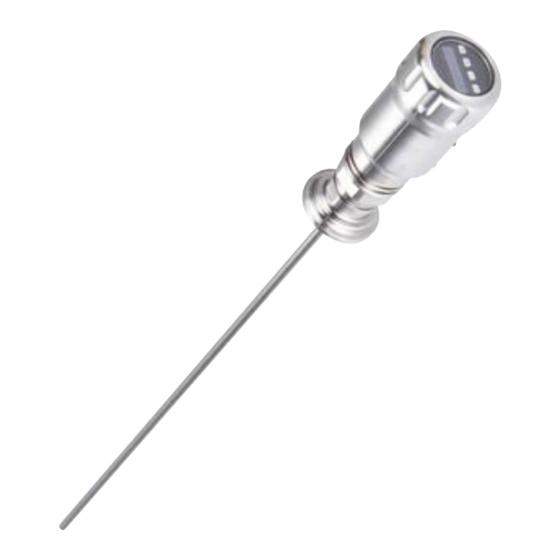
Elektrischer Anschluss
Der Sensor wird über eine fertig konfektio-
nierte Leitungsdose mit M12 x 1-Steckverbin-
der, 5-/8-polig angeschlossen. Leitungsdose
spannungsfrei auf den Sensor aufstecken und
8018147/ ZNR0/2017-07-17
festschrauben. Leitung gemäß ihrer Funktion
LFP Inox
anschließen. Nach Anlegen der Versorgungsspan-
nung führt der Sensor einen Selbsttest durch – im
eingebauten Zustand ist nach abgeschlossenem
Selbsttest (< 5 s) der Sensor betriebsbereit – das
Quickstart
Display zeigt den aktuellen Messwert an.
1 L
+
: Versorgungsspannung, braun
L
+
: Supply voltage, brown
2 Q
: Analog Strom-/Spannungsausgang, weiß
A
Q
: Analog current-/voltage output, white
A
3 M: Masse, OUT- für Strom-/Spannungsausgang, blau
M: Ground, OUT- for current-/voltage output, blue
4 C/Q
: Schaltausgang 1, PNP/IO-Link-Kommunikation, schwarz
1
C/Q
: Switching output 1, PNP/IO-Link communication, black
1
5 Q
: Schaltausgang 2, PNP/NPN, grau
2
Q
: Switching output 2, PNP/NPN, grey
2
ENGLISH
Einbaubedigungen
Der LFP wird mittels seines Prozessanschlusses
senkrecht von oben in den Behälter oder Bypass
montiert. Der Füllstandsensor LFP verfügt über
einen G ¾ oder ¾" NPT Gewindeanschluss.
Ein minimaler Stutzendurchmesser gemäß nachfol-
gender Grafik 1 ist dabei einzuhalten.
Der LFP ist so einzubauen, dass nach der Montage
genügend Abstand zu anderen Tankeinbauten
(z. B. Zulaufrohre, andere Messgeräte), der
Behälterwand oder zum Behälterboden besteht.
Mindestabstände sind ebenfalls in der Grafik 1
beschrieben. Der LFP kann auch in einem metalli-
schen Tauchrohr oder Bypass eingesetzt werden.
Die Einbaubedingungen sind in der Grafik 2
dargestellt. Es ist darauf zu achten, dass zwischen
Messgerät LFP und dem Tank/Bypass eine gute
metallische Verbindung besteht. Beim Betrieb des
Sensors dürfen die Grenzen für die Umgebungs-
temperatur nicht unter- oder überschritten werden.
Das Einisolieren des Sensorgehäuses bei Tanks
mit heißen Medien ist nicht erlaubt. Der Einbauort
ist so zu wählen, dass der Sensor nicht direkt dem
Befüllstrom ausgesetzt ist. Das Sensorgehäuse ist
um 360° drehbar und somit kann der Kabelab-
gang frei eingestellt werden.
Einbau in einen Behälter siehe Grafik 1.
Hinweis: Die Abstände sind die Gleichen für den
Sensor mit abgesetzter Elektronik.
Einbau in ein metallisches Tauchrohr oder metal-
lischen Bypass siehe Grafik 2.
1
C
Electrical connection
The sensor is connected using a pre-assembled
cable socket with 1 x M12 plug connector (5-pin
/ 8-pin). With the power switched off, plug the
cable socket into the sensor and screw it tight.
Connect the cable according to its function.
After the supply voltage has been applied, the
sensor carries out a self-test. Once installed, the
sensor is ready for operation on completion of
the self-test (< 5 s). The display shows the current
measured value.
: Versorgungsspannung, weiß
1 L
+
L
+
: Supply voltage, white
2
3
2 Q
: Schaltausgang 2, PNP/NPN, braun
1
2
8
Q
: Switching output 2, PNP/NPN, brown
4
2
3 M: Masse, Bezugsmasse für Strom-/Spannungsausgang,
7
5
grün
6
M: Ground, reference potential for current/voltage
output, green
4 C/Q
: Schaltausgang 1, PNP/IO-Link-Kommunikation,
1
gelb
C/Q
: Switching output 1, PNP/IO-Link communication,
1
yellow
5 Q
: Schaltausgang 3, PNP/NPN, grau
3
Q
: Switching output 3, PNP/NPN, gray
3
6 Q
: Schaltausgang 4, PNP/NPN, rosa
4
Q
: Switching output 4, PNP/NPN, rose
4
7 Q
: Analog Strom-/Spannungsausgang, blau
A
Q
: Analog current/voltage output, blue
A
8 Keine Funktion, rot
No function, red
Installation conditions
The LFP is mounted vertically from above into the
container or bypass, using its process connection.
The LFP level sensor has a G ¾ or ¾" NPT thread-
ed connection.
A minimum nozzle diameter in accordance with
Diagram 1 below must be observed.
The LFP is to be installed in such a way that, after
it has been mounted, there is a sufficient distance
between it and the other tank components (e.g.,
supply pipes, other measuring devices) as well
as the sides or bottom of the container. These
minimum distances are also specified in Diagram
1. The LFP can also be used in a metal immer-
sion tube or bypass. The installation conditions are
shown in Diagram 2. Ensure that there is a good
metallic connection between the LFP measuring
device and the tank/bypass. When operating the
sensor, ensure that the ambient temperature
is not above or below the limits. Insulating the
sensor housing is not permitted for tanks with hot
media. When positioning the device, ensure that
the sensor is not directly exposed to the filling flow.
The sensor housing has 360° rotation, allowing
the cable outlet to be adjusted freely.
Installation in a container see picture 1.
Note: The LFP with remote amplifier has the same
distances requirements.
Installation in a metal immersion tube or metal
bypass see picture 2.
Monosonde mit metallischen Behältern
Einbau im Stutzen: D ≥ DN 25
Abstand Behälterwand/ Behälterboden:
A ≥ 50 mm; B ≥ 10 mm
Abstand zu Behältereinbauten: ≥ 100mm
Koaxialrohr in metallischen und nichtme-
tallischen Behältern
D
C = Bei einer Koaxialsonde sind
keine Mindestabstände zur Behälterwand
und zu einbauten einzuhalten
A
Koaxialsonde
Monosonde
Unit with mono probe mounted in metal
coaxial tube
mono probe
tank
Installation in noozle: D ≥ DN25 (1")
Distance tank wall/tank bottom:
A ≥ 50 mm (1.97"); B ≥ 10 mm (0.40")
Distance to other tank ttings: ≥100 mm
(3.94")
Unit with coaxial tube for metal and non
metal tank
C = with a coaxial tube there are no
minimum distances to the tank wall or to
other tank ttings required
Maßzeichnungen/Dimensional drawings
Monosonde/monoprobe
mit Koxialrohr/with coaxial probe
32
36
(1.26)
(1.42)
G 3/4 A
3/4" NPT
G 3/4 A
3/4" NPT
7
(
0.28)
20
(0.78)
mit Leitungsverschraubung /with cable
36
(1.42)
G 3/4 A
3/4" NPT
7
(
0.28)
mit abgesetzter Elektronik /with remote amplifier
36
(1.42)
6
40
(0.24)
(1.58)
54
(
2.13)
36
40
(1.42)
(
1.58)
G 3/4 A
3/4" NPT
7
38
(
0.28)
(1.50)
2
D
8018147/ZNR0/2017-07-17 ∙ Printed in Germany (GW/KE) ∙ Subject to change without notice ∙ SICK AG ∙ Waldkirch ∙ Germany ∙ www.sick.com
Alle Maße in mm
All dimensions in mm (inch )
54
(
2.13)
M12x1
M: Messbereich
L: Sondenlänge
IA: Inaktiver Bereich am Prozessanschluss
25 mm
IAE: Inaktiver Bereich am Sondendende
10 mm
M: Measuring range
L: Probe length
IA: Inactive area process connection 25 mm
(0.79'')
IAE: Inactive area at probe end 10 mm
(0.39'')
54
(
2.13)
M12
C: Leitungslänge
IA: Inaktiver Bereich am Prozessanschluss
20 mm / 40 mm
IAE: Inaktiver Bereich am Sondendende
10 mm
C: Cable length
IA: Inactive area process connection 20 mm
(0.79'') / 40 mm (1.58'')
IAE: Inactive area at probe end 10 mm
(0.39'')
D ≥ DN 40
Abstand zu Bypassboden/
Behälterboden
B ≥ 15 mm
Distance to bypass bottom/
tank bottom
B ≥ 15 mm
Zentrieren
Center

Verwandte Anleitungen für SICK LFP Inox


Inhaltszusammenfassung für SICK LFP Inox
- Seite 1 Anliefergebietes. other tank ttings required 8018147/ZNR0/2017-07-17 ∙ Printed in Germany (GW/KE) ∙ Subject to change without notice ∙ SICK AG ∙ Waldkirch ∙ Germany ∙ www.sick.com...
- Seite 2 Gemäß UL-Listing: Verschmutzungsgrad 3 (UL61010-1: 2012-05); operating altitude of 3.000 m above sea level Siehe Betriebsanleitung auf www.sick.de (SICK Art-Nr: 8014485). See operating instructions on www.sick.com (SICK part no. Luftfeuchtigkeit: 80 % bei Temperaturen bis zu 31 °C; Einsatzhöhe: max 8014485).