Herunterladen Inhalt Inhalt Diese Seite drucken
Fujitsu D2778 Handbuch
Vorschau ausblenden Andere Handbücher für D2778:
Inhaltsverzeichnis

Werbung

Verfügbare Sprachen

Verfügbare Sprachen

Technical Description
Mainboard
Mainboard D2778

Werbung

Kapitel

Inhaltsverzeichnis
loading

Inhaltszusammenfassung für Fujitsu D2778

  • Seite 1 Technical Description Mainboard Mainboard D2778...
  • Seite 2 For automatic driver updates, go to: "http://support.ts.fujitsu.com/support/index.html" Should you have any technical questions, please contact: ● our Hotline/Service Desk (see the Service Desk list or visit: "http://ts.fujitsu.com/support/servicedesk.html") ● your sales partner ● your sales outlet We hope you really enjoy using your new Fujitsu system.
  • Seite 4 Any liability that the data and illustrations are complete, actual or correct is excluded. Designations may be trademarks and/or copyrights of the respective manufacturer, the use of which by third parties for their own purposes may infringe the rights of such owner. For further information see "http://ts.fujitsu.com/terms_of_use.html" Order No. Fujitsu Technology Solutions: A26361-D2778-Z210-2-8N19, Edition 2...
  • Seite 5: Technical Description

    Mainboard D2778 Technical Description English Deutsch...
  • Seite 6 All other trademarks used in this document are trademarks or registered trademarks of their respective owners and are recognised as being protected. Copyright © Fujitsu Technology Solutions GmbH 2011 All rights, including rights of translation, reproduction by printing, copying or similar methods, of the whole document or parts thereof, are reserved.
  • Seite 7: Inhaltsverzeichnis

    Mainboard D2778 English - 1 Content Overview Mainboard D2778 ....................... 3 Mainboard D2778..........................5 Notational conventions ......................... 5 Important notes............................. 6 Information about boards ......................6 Hardware Specifications........................8 Block Diagram ............................ 10 System security features ........................11 Basic security features ....................... 11 Trusted Platform Module (TPM) ....................
  • Seite 8 Mainboard D2778 2 – English Fujitsu Technology Solutions...
  • Seite 9: Overview Mainboard D2778

    Mainboard D2778 English - 3 Overview Mainboard D2778 dual channel 2x PS2 (internal or external via SPDIF special wire) Firewire 1 = Key 8+9+10+11 2 = Not connected LGA1366 LAN 0 3 = VCC X USB 6+7 4 = VCC Y...
  • Seite 10 Mainboard D2778 4 – English Fujitsu Technology Solutions...
  • Seite 11: Mainboard D2778

    English - 5 Mainboard D2778 Based on the Intel® X58 Express chipset, the D2778 features some state-of-the-art technologies such as Dual-Core Xeon® Processor Series as well as Quad-Core Xeon® Processor Series support in LGA 1366 socket, multiple PCI-Express buses, triple channel DDR3 memory design, onboard PCI- Express Gigabit Ethernet, SATA ports, multiple USB 2.0 (Universal Serial Bus) and one eSATA port.
  • Seite 12: Important Notes

    Mainboard D2778 6 – English Important notes With the mainboard installed you must open the system to access the mainboard. How to dismantle and reassemble the system is described in the operating manual accompanying the system. Connecting cables for peripherals must be adequately shielded to avoid interference.
  • Seite 13 Mainboard D2778 English - 7 Notice for the USA Compliance Information Statement (Declaration of Conformity Procedure) DoC FCC Part 15: This device complies with part 15 of the FCC Rules Operation is subject to the following conditions: This device may not cause harmful interference, and This device must accept any interference received including interference that may cause undesired operation.
  • Seite 14: Hardware Specifications

    Mainboard D2778 8 – English Hardware Specifications CPU – LGA1366 socket LAN – 10/100/1000 Ethernet Controller ● One CPU-sockets ● WakeOnLAN by interesting packets, link status change and Magic-PacketTM ● Intel® Xeon Processors in the LGA1366 package: Nehalem EP 2S or ●...
  • Seite 15 Mainboard D2778 English - 9 Audio Advanced system monitoring and management ● Realtek ALC 663 ● System Management ● Host based Audio with 6-channel HD Audio ● Thermal Management ● Stereo Head-Phone Out ● Automatic system reset (ASR) ● Sound via internal system speaker ●...
  • Seite 16: Block Diagram

    Mainboard D2778 10 – English Block Diagram Memory Bus Nehalem-WS 1S 3 channels 3x2 DDR3 Nehalem-EP 2S 800/1066/1333 UDIMM only Intel Quick Path Interconnect PCIE x16 PCIE x16 Slot Intel X58 PCIE x16 Express PCIE x16 Slot PCIE x4 36xPCIE...
  • Seite 17: System Security Features

    Mainboard D2778 English - 11 System security features Basic security features For a complete description of the basic security features have a look at the BIOS Specification. Trusted Platform Module (TPM) Trusted Platform Modules are a Trusted Computing Group (TCG) security solution to increase the system security.
  • Seite 18: Smartcase Dynamicusb

    Mainboard D2778 12 – English SmartCase DynamicUSB This is hardware security circuit which will disable the USB-port if a USB-device is removed so no other USB-devices can be attached. Goal is that no data can be stolen by connecting i.e. a USB- stick.
  • Seite 19: Choose Proper Parts For Your System

    The processor host bus, or called Quick Path Interconnect (QPI), auto-operates at a frequency up to 6.4 GT/s. ● Single/Dual Processor System D2778 board supports one Dual-Core or Quad-Core or Quad-Core or 6 core (only Cxx board version) Intel® Xeon® Processors. System Memory Interface ●...
  • Seite 20: Bios Post-Codes (Port 80 Status Indicators)

    Mainboard D2778 14 – English BIOS POST-Codes (Port 80 status indicators) BIOS-POST codes are visible on the LCD-display (connected to the LCD-connector). Post-Code Overview: Standard system BIOS: POST Code Error Beeps Description Initialize IPMI Verify Real Mode Disable non-maskable interrupt(NMI)
  • Seite 21 Mainboard D2778 English - 15 POST Code Error Beeps Description Set segment register ES to 4GB access Enable A20 line 1-3-3-1 Autosize DRAM Initialize POST memory manager Clear 512KB base RAM Initialize CMOS emulation 1-3-4-1 RAM failure on address line xxxx...
  • Seite 22 Mainboard D2778 16 – English POST Code Error Beeps Description Set key click if enabled USB initialization Initialize 1394 devices 2-2-3-1 Test for unexpected interrupts Initialize POST display service Display prompt "Press F2 to Enter Setup" Disable CPU cache Test RAM between 512KB and 640KB...
  • Seite 23 Mainboard D2778 English - 17 POST Code Error Beeps Description Configure motherboard configurable devices(MCD) Initialize BIOS data area(BDA) Enable non-maskable interrupt(NMI) Initialize extended BIOS data area(EBDA) Test and initialize PS/2 mouse Initialize floppy controller Determine number of ATA drives Initialize hard disk controllers...
  • Seite 24 Mainboard D2778 18 – English POST Code Error Beeps Description Store CMOS emulation values to non-volatile area. One short beep before boot Terminate quiet boot Check password ACPI support Prepare boot Initialize DMI parameters Initialize PnP option ROMs Clear parity checkers...
  • Seite 25: Power Supply Considerations

    Power Supply Considerations Power Connectors The D2778 is powered via a split plane power supply unit (PSU) using three +12 V rails providing 500 W continuous power and five +12 V lines providing 700 W continuous power. Three rails are intended for use with the system board and two for use with peripherals (hard disk, display adapter).
  • Seite 26: Board Installation

    Mainboard D2778 20 – English Board Installation Fan Connector (internal) Pin1: GND Pin 1 Pin2: +12V Power Pin3: FAN Sense Pin 4 Pin4: Fan PWM This 4-pin fan connector supports tachometer monitoring. There are five 4-pin fan connectors on D2618. Use these connectors to connect chassis and processor cooling fans to your motherboard.
  • Seite 27: Frontpanel Connector (Internal)

    Normally, a chassis has some control or signal wires can be connected onto a motherboard for hard drive LED, Power LED, power button, and reset button; The front panel connector has been implemented on D2778 for such purposes. PIN Signal...
  • Seite 28: Communiction Connectors

    Mainboard D2778 22 – English Communiction connectors USB port (internal) – Internal/Front PIN Signal PIN Signal Pin 1 Pin 2 Not connected VCC AUX (polyswitch fused) VCC AUX (polyswitch fused) Data negative Port X Data negative Port X Data positive Port X...
  • Seite 29: User Experience Connector

    Mainboard D2778 English - 23 User experience connector Audio SPDIF OUT (internal) PIN Signal Pin 1 SPDIF out System monitoring and management connectors SCSI LED connector (Internal) PIN Signal Pin 1 Not connected SCSI-ON LED (low asserted input) SCSI-ON LED (low asserted input)
  • Seite 30: Parallel Port

    Mainboard D2778 24 – English Parallel Port Parallel Port ( internal ) PIN Signal PIN Signal Pin 1 Pin 2 Strobe AutoFD Data0 Error Data1 Init Data2 Sel_L Data3 Data4 Data5 Data6 Data7 Busy Empty Select COM2 Ports PIN Signal...
  • Seite 31: Installing The Memory

    Installing the Memory Before attempting to install any memory, make sure that the memory you have is compatible with the motherboard as well as the processor. The D2778 board supports up to six 240-pin 1.5 V 800/1066/1333 MHz DDR3 modules.
  • Seite 32: Memory Installation Procedure

    Mainboard D2778 26 – English Memory Installation Procedure When installing memory modules, make sure the modules align properly with the memory socket. There should be keys (small indents) on your memory modules that fit according to the keys in the memory socket.
  • Seite 33 Mainboard D2778 English - 27 Removing a memory module ► Push the clips on the right and left of the memory slot outward (1). ► Pull the memory module out of the memory slot (2). When installing memory, a module may require a considerable amount of force to seat properly, although this is very rare.
  • Seite 34: Installing The Processor And Heatsink

    Installing the processor The processor socket ist covered with a protective cap to protect the spring contacts In a warranty case the mainboard can only be taken back by Fujitsu Technology Solutions with the protective cap secured! Never touch the underside of the processor. Even minor soiling such as grease from the skin can impair the processor's operation or destroy the processor.
  • Seite 35 Mainboard D2778 English - 29 Hold the new processor between your thumb and index finger and insert it into the socket (b) so that the marking of the processor is aligned with the marking on the socket (a). ► Fold down the frame (1).
  • Seite 36: Mounting Heat Sink

    Mainboard D2778 30 – English Mounting heat sink Use only the heat sink supplied with your system! Be sure to use heat conducting material between the processor and the heat sink. If a heat conducting pad (rubber-like foil) is already applied to the heat sink, then use it. Otherwise you must apply a very thin layer of heat conducting paste.
  • Seite 37: Installing Add-In Cards

    Mainboard D2778 English - 31 Installing Add-In Cards Before installing add-in cards, please check if they are fully compatible with your motherboard. PCIe x4/x8 PCIe x16 PCIe x4/x8 PCIe x16 PCI 32 PCI 32 Simply find the appropriate slot for your add-in card and insert the card firmly. Do not force any add- in cards (or anything else) into any slots if they won’t seat in place.
  • Seite 38: Connecting External Devices

    Mainboard D2778 32 – English Connecting External Devices Connecting external devices to the motherboard is an easy task. The standard devices you should expect to plug into the motherboard are keyboards, mouse, and printer cables. The following diagram will detail the ATX port stack for the following board:...
  • Seite 39: Installing The Power Supply

    ● 8-pin PWR2 power connector The D2778 is powered via a split plane power supply unit (PSU) using three +12 V rails providing 500 W continuous power and five +12 V lines providing 700 W continuous power. Three rails are intended for use with the system board and two for use with peripherals (hard disk, display adapter).
  • Seite 40: Replacing Lithium Battery

    Mainboard D2778 34 – English Replacing lithium battery In order to permanently save the system information, a lithium battery is installed to provide the CMOS-memory with a current. A corresponding error message notifies the user when the charge is too low or the battery is empty. The lithium battery must then be replaced.
  • Seite 41: Bios Update

    English - 35 BIOS update When should a BIOS update be carried out? Fujitsu Technology Solutions makes new BIOS versions available to ensure compatibility to new operating systems, new software or new hardware. In addition, new BIOS functions can also be integrated.
  • Seite 42: Glossary

    Mainboard D2778 36 – English Glossary The technical terms and abbreviations given below represent only a selection of the full list of common technical terms and abbreviations. Not all technical terms and abbreviations listed here are valid for the described mainboard.
  • Seite 43 Mainboard D2778 Deutsch - Inhalt Übersicht über das Mainboard D2778 ....................2 Mainboard D2778..........................4 Handbuchkonventionen........................4 Wichtige Hinweise ..........................5 Allgemeine Informationen im Zusammenhang mit Boards............5 Hardware-Spezifikationen ........................7 Blockdiagramm............................. 9 Systemsicherheitsfunktionen......................10 Grundlegende Sicherheitsfunktionen ..................10 Trusted Platform Module (TPM) ....................10 SmartCase DynamicUSB ......................
  • Seite 44: Übersicht Über Das Mainboard D2778

    Deutsch Mainboard D2778 2 – Übersicht über das Mainboard D2778 dual channel 2x PS2 (internal or external via SPDIF special wire) Firewire 1 = Key 8+9+10+11 2 = Not connected LGA1366 LAN 0 3 = VCC X USB 6+7 4 = VCC Y...
  • Seite 45 Mainboard D2778 Deutsch - Fujitsu Technology Solutions...
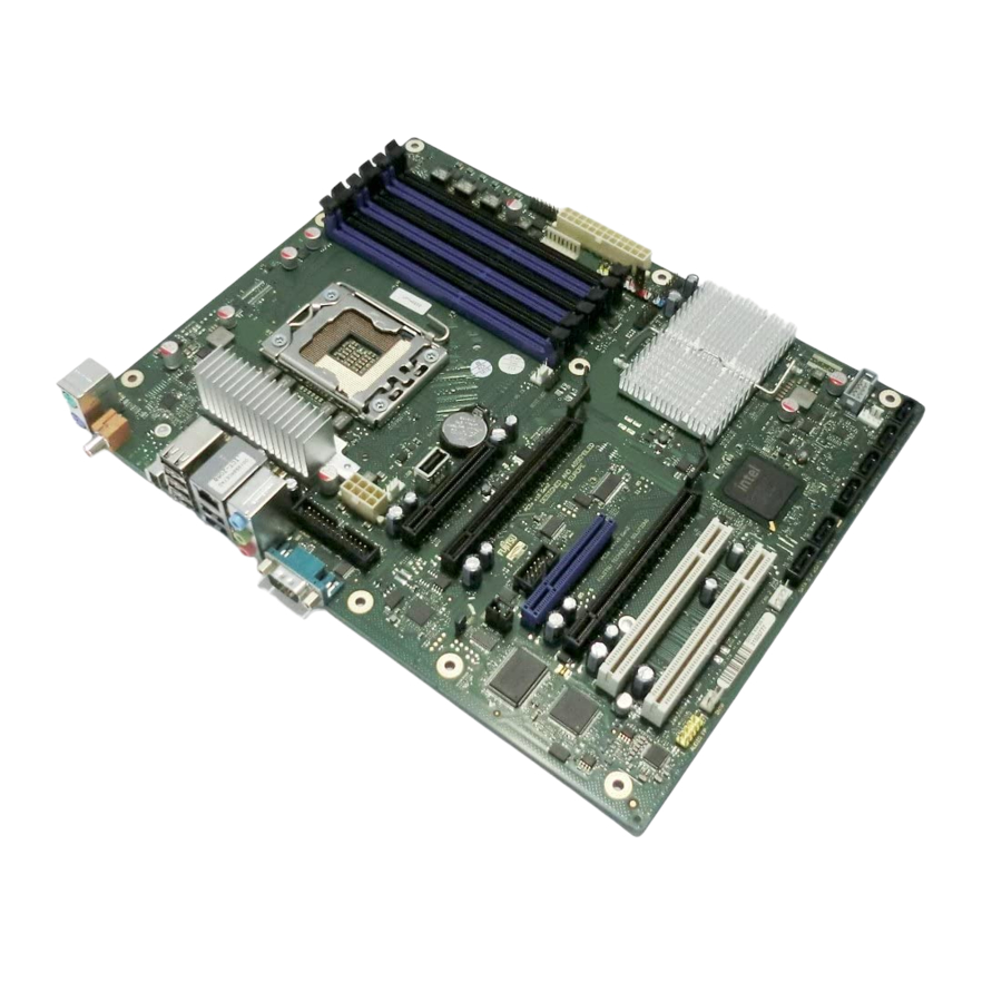
  • Seite 46: Mainboard D2778

    4 – Mainboard D2778 Basierend auf dem Intel® X58 Chipsatz zeichnet sich das D2778 durch eine Reihe hochmoderner Technologien aus. Dazu zählen: Support für die Dual-Core Xeon® Prozessor-Serien sowie die Quad-Core Xeon® Prozessor-Serien im LGA 1366 Sockel, multiple PCI-Express Busse, Triple Channel DDR3 Speicherdesign, Onboard PCI-Express Gigabit Ethernet, SATA-Ports, multiple USB 2.0- (Universal Serial Bus) und einem eSATA-Port.
  • Seite 47: Wichtige Hinweise

    Mainboard D2778 Deutsch - Wichtige Hinweise Zum Zugriff auf das installierte Mainboard muss das System geöffnet werden. Wie das System auseinandergebaut und wieder zusammengesetzt wird, ist im begleitenden Bedienerhandbuch beschrieben. Zur Vermeidung von Interferenzen müssen die Verbindungskabel für die Peripherie entsprechend abgeschirmt sein.
  • Seite 48 Deutsch Mainboard D2778 6 – Boards mit elektrostatisch empfindlichen Geräten (Electrostatic Sensitive Devices (ESD)) sind durch ein Etikett entsprechend gekennzeichnet. Bitte beachten Sie beim Umgang mit Boards, auf denen sich solche ESDs befinden, unbedingt Folgendes: ● Vor der Arbeit müssen Sie immer für eine statische Entladung (z. B. durch Berühren eines geerdeten Objekts) sorgen.
  • Seite 49: Hardware-Spezifikationen

    Mainboard D2778 Deutsch - Hardware-Spezifikationen CPU – LGA1366 Sockel LAN – 10/100/1000 Ethernet Controller ● Ein CPU-Sockel ● WakeOnLAN durch interessante Pakete, Verbindungsstatusänderung und Magic- ● Intel® Xeon Prozessoren im LGA1366- Packet™ Paket: Nehalem EP 2S, Nehalem WS 1S oder Westmere EP ●...
  • Seite 50 Deutsch Mainboard D2778 8 – Audio Erweiterte Systemüberwachung und - verwaltung ● Realtek ALC 663 ● System Management ● Host-basiertes Audio mit 6-Kanal HD Audio ● Thermal Management ● Stereokopfhörerausgang ● Automatic System Reset (ASR, automatisches Zurücksetzen des ● Sound über interne Systemlautsprecher Systems) ●...
  • Seite 51: Blockdiagramm

    Mainboard D2778 Deutsch - Blockdiagramm Memory Bus Nehalem-WS 1S 3 channels 3x2 DDR3 Nehalem-EP 2S 800/1066/1333 UDIMM only Intel Quick Path Interconnect PCIE x16 PCIE x16 Slot Intel X58 PCIE x16 Express PCIE x16 Slot PCIE x4 36xPCIE PCIE x8 Slot...
  • Seite 52: Systemsicherheitsfunktionen

    Deutsch Mainboard D2778 10 – Systemsicherheitsfunktionen Grundlegende Sicherheitsfunktionen Eine vollständige Beschreibung der grundlegenden Sicherheitsfunktionen ist in der BIOS- Spezifikation zu finden. Trusted Platform Module (TPM) Bei Trusted Platform Modules handelt es sich um eine Sicherheitslösung der Trusted Computing Group (TCG) zur Steigerung der Systemsicherheit. Das TPM befindet sich auf dem Motherboard und nutzt zur Kommunikation mit dem Rest der Plattform den LPC-Bus.
  • Seite 53: Smartcase Dynamicusb

    Mainboard D2778 Deutsch - SmartCase DynamicUSB Dies ist ein Hardware-Sicherheitsschaltkreis, durch den der USB-Port beim Entfernen eines USB- Geräts deaktiviert wird, so dass keine anderen USB-Geräte angeschlossen werden können. Auf diese Weise wird der Datendiebstahl durch Anschließen etwa eines USB-Sticks verhindert. Diese Funktion wird komplett über Hardware und BIOS realisiert.
  • Seite 54 Deutsch Mainboard D2778 12 – Folgende Geräteklassen werden innerhalb der USB-Spezifikation angegeben: Fett/kursiv dargestellte Klassen sind keine zulässigen USB-Geräte (wenn die Option SmartCase DynamicUSB aktiviert ist) – Ports, an denen während der BIOS-Phase solche Geräte angeschlossen sind, werden durch das BIOS deaktiviert.
  • Seite 55: Auswahl Der Korrekten Teile Für Das System

    Der Host-Bus des Prozessors, auch als Quick Path Interconnect (QPI) bezeichnet, arbeitet selbstständig mit einer Frequenz von bis zu 6,5 GT/s. ● Einzel-/Dualprozessorsystem Das D2778 unterstützt einen oder zwei Dual-Core oder Quad-Core oder 6 Core ( nur Cxxx Board-Version) für Intel® Xeon® Prozessor(en). Systemspeicherschnittstelle ●...
  • Seite 56: Bios Post-Codes (Port 80-Statusanzeigen)

    Deutsch Mainboard D2778 14 – BIOS POST-Codes (Port 80-Statusanzeigen) BIOS-POST-Codes werden auf dem LCD-Display (angeschlossen an den LCD-Anschluss) angezeigt. Übersicht über die Post-Codes: Standardsystem BIOS: POST-Code Akustische Beschreibung Fehlersignale IPMI initialisieren Real Mode verifizieren NMI deaktivieren (NMI = Non-Maskable Interrupt)
  • Seite 57 Mainboard D2778 Deutsch - POST-Code Akustische Beschreibung Fehlersignale 8742-Tastatur-Controller testen ES des Segment-Registers auf 4 GB-Zugriff setzen A20-Leitung aktivieren 1-3-3-1 DRAM automatisch skalieren POST-Speicherverwaltung initialisieren 512 KB-Basis-RAM löschen CMOS-Emulation initialisieren 1-3-4-1 RAM-Fehler auf Adressleitung xxxx 1-3-4-3 RAM-Fehler bei Datenbits xxx des niedrigen Byte des...
  • Seite 58 Deutsch Mainboard D2778 16 – POST-Code Akustische Beschreibung Fehlersignale Boot-Abfolge vorab initialisieren EISA-Board initialisieren Tastatur testen Tastaturklick setzen, falls aktiviert USB-Initialisierung 1394-Geräte initialisieren 2-2-3-1 Test für unerwartete Interrupts durchführen POST-Anzeige-Service initialisieren Eingabeaufforderung "Press F2 to Enter Setup" anzeigen CPU-Cache deaktivieren...
  • Seite 59 Mainboard D2778 Deutsch - POST-Code Akustische Beschreibung Fehlersignale Non-MCE IDE-Controller konfigurieren Externe Parallel-Ports erkennen und installieren PC-kompatible PnP ISA-Geräte initialisieren Onboard I/O-Ports neu initialisieren MCDs konfigurieren (MCD = Motherboard Configurable Devices) BDA initialisieren (BDA = BIOS Data Area) NMI aktivieren (NMI = Non-Maskable Interrupt)
  • Seite 60 Deutsch Mainboard D2778 18 – POST-Code Akustische Beschreibung Fehlersignale Setup aufrufen Boot-Markierung löschen Auf Fehler prüfen Support für RomPilot deaktivieren Booten des Betriebssystems vorbereiten (POST abgeschlossen) CMOS-Emulationswerte in nicht-flüchtigem Bereich speichern Ein kurzer Signalton vor dem Booten Quiet Boot beenden Kennwort überprüfen...
  • Seite 61 Mainboard D2778 Deutsch - POST-Code Akustische Beschreibung Fehlersignale BIOS-Stack und verschiedene Arbeitspuffer initialisieren Unbekannter Interrupt Speicherberichtschnittstelle initialisieren CPU-Marke/Hersteller bestimmen PCCards (CardBus,...) initialisieren Support für FirstWare ASF initialisieren IPMI initialisieren, 2. Teil PCIe-Geräte vorab initialisieren Support für FirstWave, 2. Teil Microcode-Update verifizieren Support für Remote Flash initialisieren...
  • Seite 62: Betrachtungen Zur Stromversorgung

    Betrachtungen zur Stromversorgung Netzstecker Das D2778 wird über ein Split-Plane-Netzteil (PSU) bei drei +12 V Strängen mit 500 W und bei fünf +12 V-Strängen mit 700 W durchgängiger Leistung betrieben. Drei Stränge sind für das System- Board und zwei für Peripheriegeräte (Festplatten, Grafikkarte) vorgesehen. Wie nachfolgend aufgelistet, sind auf dem Motherboard zwei Netzstecker vorhanden.
  • Seite 63: Installation Des Boards

    Pin4: Fan PWM Dieser 4-polige Lüfteranschluss unterstützt die Geschwindigkeitsüberwachung Auf dem D2778 sind fünf 4-polige Lüfteranschlüsse implementiert. Über diese Anschlüsse können Lüfter zur Kühlung von Gehäuse und Prozessor mit dem Motherboard verbunden werden. Kühlende Lüfter tragen zur Systemstabilität und -zuverlässigkeit während der Lebensdauer des Produkts bei.
  • Seite 64: Frontblendenanschluss (Intern)

    In der Regel verfügt ein Gehäuse über einige Kontroll- oder Signalkabel, die an ein Motherboard für die Festplatten-LED, Netz-LED, den Betriebsschalter und die Reset-Taste angeschlossen werden können. Für solche Zwecke wurde der Frontblendenanschluss auf dem D2778 implementiert. POL Signal POL Signal...
  • Seite 65: Kommunikationsanschlüsse

    Mainboard D2778 Deutsch - Kommunikationsanschlüsse USB-Port (intern) – Intern/Vorderseite POL Signal POL Signal Pin 1 Pin 2 Nicht angeschlossen VCC AUX VCC AUX Data negative Port X Data negative Port X Data positive Port X Data positive Port X Nicht angeschlossen...
  • Seite 66: Anschluss Benutzererfahrung

    Deutsch Mainboard D2778 24 – Anschluss Benutzererfahrung Audio SPDIF OUT (intern) POL Signal Pin 1 SPDIF out Anschlüsse für Systemüberwachung und - verwaltung SCSI LED-Anschluss (Intern) POL Signal Pin 1 Nicht angeschlossen SCSI-ON LED (niedrig eingestellter Input) SCSI-ON LED (niedrig eingestellter Input)
  • Seite 67: Konfigurations-Jumper Innerhalb Der Frontblende

    Mainboard D2778 Deutsch - Konfigurations-Jumper innerhalb der Frontblende Standard-Jumper-Position (Password Skip (Kennwortüberspringung) und Recovery BIOS deaktiviert) Pin 16 Pin 1 Pin 2 Kennwortüberspringung aktiviert Pin 16 Recovery BIOS aktiviert Pin 16 Parallel Port Parallel Port ( intern ) PIN Signal...
  • Seite 68: Com2 Ports

    Deutsch Mainboard D2778 26 – COM2 Ports PIN Signal PIN Signal Pin 1 Pin 2 DCD 2 DSR 2 SIN 2 RTS 2 SOUT 2 CTS 2 DTR 2 RI 2 TPM-Jumper Signal RST_PCI_TPM_L TPM_RESET_L Standardmäßig ist der TPM-Jumper gesetzt. Das Entfernen des Jumpers führt zur Deaktivierung der TPM-Funktionalität.
  • Seite 69: Speicherinstallation

    Speicherinstallation Vor der Installation muss sichergestellt werden, dass der einzusetzende Speicher kompatibel mit dem Motherboard und dem Prozessor ist. Das D2778-Board unterstützt bis zu sechs 240-polige, 1,5 V, 800/1066/1333 MHz DDR3-Module. Hier einige Kernpunkte, die Sie vor der Speicherinstallation auf dem D2778 beachten müssen:...
  • Seite 70: Vorgehen Bei Der Speicherinstallation

    Deutsch Mainboard D2778 28 – Vorgehen bei der Speicherinstallation Bei der Installation von Speichermodulen müssen Sie darauf achten, dass die Module korrekt am Speichersockel ausgerichtet sind. Auf den Speichermodulen sollten sich kleine Kerben befinden, die zu den Kerben im Speichersockel passen. DDR-Module verfügen nur über eine Kerbe, die sich unmittelbar neben dem Mittelpunkt des Moduls/Sockels befindet.
  • Seite 71 Mainboard D2778 Deutsch - Entfernen eines Speichermoduls ► Die Klammern rechts und links am Speichersteckplatz nach außen drücken (1). ► Das Speichermodul aus dem Speichersteckplatz (2) ziehen. Mitunter kann schwierig sein, ein Modul in die korrekte Position zu bringen. Dies ist jedoch nur äußerst selten der Fall.
  • Seite 72: Installation Von Prozessor Und Wärmeableiter

    Installation von Prozessor und Wärmeableiter Prozessorinstallation Der Prozessorsockel ist zum Schutz der Federkontakte mit einer Schutzkappe versehen. In einem Garantiefall kann das Mainboard von Fujitsu Technology Solutions nur mit angebrachter Schutzkappe zurückgenommen werden! Niemals die Unterseite des Prozessors berühren. Selbst kleinste Verschmutzungen durch Hautfette können den Prozessorbetrieb beeinträchtigen oder zur Zerstörung des...
  • Seite 73 Mainboard D2778 Deutsch - Den neuen Prozessor zwischen Daumen und Zeigefinger halten und in den Sockel (b) einsetzen, so dass die Markierung auf dem Prozessor mit der Markierung auf dem Sockel (b) abschließt. ► Den Rahmen nach unten klappen (1).
  • Seite 74: Montage Des Wärmeableiters

    Deutsch Mainboard D2778 32 – Montage des Wärmeableiters Verwenden Sie nur den zum Lieferumfang zählenden Wärmeableiter! Sorgen Sie dafür, dass zwischen Prozessor und Wärmeableiter wärmeleitendes Material verwendet wird. Wenn am Wärmeableiter bereits ein wärmeleitendes Polster (gummiartige Folie) angebracht ist, nutzen Sie dieses. Andernfalls muss eine sehr dünne Schicht wärmeleitender Paste aufgetragen werden.
  • Seite 75: Installation Von Add-In-Karten

    Mainboard D2778 Deutsch - Installation von Add-In-Karten Prüfen Sie vor der Installation von Add-In-Karten, ob diese vollständig kompatibel mit dem Motherboard sind. PCIe x4/x8 PCIe x16 PCIe x4/x8 PCIe x16 PCI 32 PCI 32 Einfach den passenden Steckplatz für die Add-In-Karte suchen und die Karte fest einfügen. Wenn sich Add-In-Karten (oder andere Komponenten) nicht ordnungsgemäß...
  • Seite 76: Anschließen Von Externen Geräten

    Deutsch Mainboard D2778 34 – Anschließen von externen Geräten Das Anschließen von externen Geräten an das Motherboard ist eine einfache Aufgabe. Zu den Standardkomponenten, die üblicherweise an das Motherboard angeschlossen werden, zählen Tastatur-, Maus- und Druckerkabel. In nachstehendem Diagramm wird der ATX-Port-Stack für...
  • Seite 77: Installieren Des Netzteils

    ● 8-poliger PWR2-Netzanschluss Das D2778 wird über ein Split-Plane-Netzteil (PSU) bei drei +12 V Strängen mit 500 W und bei fünf +12 V-Strängen mit 700 W durchgängiger Leistung betrieben. Drei Stränge sind für das System- Board und zwei für Peripheriegeräte (Festplatten, Grafikkarte) vorgesehen.
  • Seite 78: Austauschen Des Lithium Akkus

    Deutsch Mainboard D2778 36 – Austauschen des Lithium Akkus Der installierte Lithium Akku versorgt den CMOS-Speicher mit Strom, damit die Systeminformationen permanent gespeichert bleiben. Wenn der Akku leer oder fast leer ist, wird dem Benutzer eine entsprechende Fehlermeldung angezeigt. Der Lithium-Akku muss dann ausgetauscht werden.
  • Seite 79: Bios-Update

    Deutsch - BIOS-Update Wann sollte ein BIOS-Update durchgeführt werden? Fujitsu Technology Solutions stellt neue BIOS-Versionen zur Verfügung, um die Kompatibilität zu neuen Betriebssystemen, zu neuer Software oder zu neuer Hardware zu gewährleisten. Außerdem können neue BIOS-Funktionen integriert werden. Ein BIOS-Update sollte auch immer dann durchgeführt werden, wenn ein Problem besteht, das sich durch neue Treiber oder neue Software nicht beheben lässt.
  • Seite 80: Glossar

    Deutsch Mainboard D2778 38 – Glossar Die nachfolgend aufgelisteten Begriffe und Abkürzungen stellen nur eine Auswahl der kompletten Liste mit allgemeinen technischen Begriffen und Abkürzungen dar. Nicht alle hier aufgelisteten technischen Begriffe und Abkürzungen beziehen sich auf das hier beschriebene Motherboard.

Inhaltsverzeichnis