Herunterladen Inhalt Inhalt Diese Seite drucken
Megger DLRO-10X Bedienungsanleitung

Megger DLRO-10X Bedienungsanleitung

Digital low resistance ohmmeter
Vorschau ausblenden Andere Handbücher für DLRO-10X:
Inhaltsverzeichnis

Werbung

Verfügbare Sprachen
  • DE

Verfügbare Sprachen

  • DEUTSCH, seite 50
DLRO
-10 & DLRO
®
Digital Low Resistance Ohmmeter
USER GUIDE
GUIDE DE L'UTILISATEUR
BEDIENUNGSANLEITUNG
GUIDA PER L'UTENTE
GUIA DEL USUARIO
-10X
®
M

Werbung

Inhaltsverzeichnis
loading

Inhaltszusammenfassung für Megger DLRO-10X

  • Seite 1 DLRO -10 & DLRO -10X ® ® Digital Low Resistance Ohmmeter USER GUIDE GUIDE DE L’UTILISATEUR BEDIENUNGSANLEITUNG GUIDA PER L’UTENTE GUIA DEL USUARIO...
  • Seite 2: Safety Warnings

    If it is impossible to de-energise the circuit, (e.g. high voltage batteries cannot be switched off while their connections are tested) the user must be aware of the dangers. The instrument terminals will become live when connected to the circuit. Therefore when used on hazardous voltages custom Megger DH6, DH6-C test leads must be used. Testing inductive circuits can be hazardous: After testing an inductive load there will be an amount of energy stored in the inductance.
  • Seite 3: Inhaltsverzeichnis

    CONTENTS Safety Warnings High Power Mode General Description Unidirectional Mode General Operation - DLRO 10 Test Techniques & Applications Test Current Indicators Testing Using DH4 Duplex Handspikes Noise Lamp Testing Using Handspikes Or Individual Leads. ‘C’ & ‘P’ Indicators Test Sequence ‘V’...
  • Seite 4: General Description

    GENERAL DESCRIPTION The DUCTER DLRO 10 and DUCTER DLRO 10X make up a family of low resistance ohmmeters that measure resistances in the range from 0.1 µΩ to 2 kΩ. Both instruments provide a maximum test current of 10 Amps d.c. which is automatically selected according to the value of resistance being tested. The DLRO 10X allows you to override this automatic selection and select your own test current.
  • Seite 5: General Operation - Dlro 10

    GENERAL OPERATION - DLRO 10 ‘C’ & ‘P’ Indicators The ‘C’ lamp illuminates to indicate contact failure in the ‘C1-C2’ loop. The ‘P’ lamp illuminates when there is a break in the P1-P2 loop. ‘V’ & ‘I’ Warning Indicators If external voltage is applied to the terminals the ‘V’ lamp will flash. This is a warning that the item under test is live and might be dangerous.
  • Seite 6: General Operation - Dlro 10X

    GENERAL OPERATION - DLRO 10X charge remaining, index number of the next test, number of tests already stored and the current date and time. This screen also provides access to the menuing system, through which you set up your instrument and choose the desired test parameters. Navigation of this menuing system is by means of the cursor control and Enter key.
  • Seite 7: External Voltage Warning

    GENERAL OPERATION - DLRO 10X the current circuit is not made or “CP OPEN CIRCUIT” if both circuits are Options Menu inadequate. Check the contacts, since a measurement cannot be made if The Options menu has five options that are not related to each other, as any of these messages is visible on the display.
  • Seite 8: Download

    GENERAL OPERATION - DLRO 10X causes the entire contents of the data store to be output This option allows you to set upper and lower limits between which the to the RS232 port to the left of the display. A copy of test result average must fall if it is to be signalled as a Pass (a long tone AVO Download Manager, which facilitates downloading from the buzzer).
  • Seite 9: Delete Data

    GENERAL OPERATION - DLRO 10X month, the two-digit year, the hour of the day in 24-hour notation and With the exception of tests carried out in Continuous mode, at the end of the minute. These must be entered in this sequence regardless of the date each test you have the option to change the default by selecting STORE or format you wish to use.
  • Seite 10: Test Result Storage

    GENERAL OPERATION DLRO 10X briefly press one of the twelve keys on the keypad. You will enter a memo screen that allows you to enter up to 200 characters of alphanumeric information concerning the test. When you have entered all information press Enter and the measurement and memo will be stored regardless of whether STORE or NO STORE was selected.
  • Seite 11 GENERAL OPERATION DLRO 10X Decimal point or full stop Ω Ohms symbol lower case m (abbreviation for milli) µ Symbol for micro Symbol known as hash or pound and commonly used as shorthand for “number” Percent sign Left round bracket Right round bracket Hyphen, dash or minus sign Slash...
  • Seite 12: Test Modes

    TEST MODES TEST MODES Continuous mode DLRO 10 has 4 test modes which are selected by repeated presses of the Continuous mode requires the connections to be made before pressing Mode button. At the end of each test, DLRO 10 will display the average the Test button.
  • Seite 13: Unidirectional Mode

    Test Modes The time required for a stable reading may vary from a few seconds up to several minutes depending on the inductance and resistance of the test sample. There is no time limit for the inductive mode test, which will continue until the operator presses the Test button.
  • Seite 14: Test Techniques & Applications

    C probes. Since your DLRO always ensures good contact before applying the full Note: When used on hazardous voltages Megger DH6 test leads must test current, there will be no ‘splash’ to erode the contact tips. However, be used. should the tips become worn or blunted, they can be simply replaced by...
  • Seite 15: Test Sequence

    TEST TECHNIQUES & APPLICATIONS TEST SEQUENCE the leads and 30 W within your instrument. If the ambient temperature is high this will cause internal overheating and the message “hot” will Pressing the TEST button starts the test sequence. appear on the instrument display and testing will be halted. Contact resistance is checked by passing 100 µA through the C1-C2 After a few minutes to cool down, testing will be allowed to continue.
  • Seite 16: Battery Module And Care

    BATTERY MODULE AND CARE THE BATTERY MODULE To charge the battery, your battery module must be removed from the The battery module contains nickel-metal-hydride cells and has a built- instrument. Remove the module by pressing on the raised circular area of in battery-management system that controls charging and monitors the retaining clips and pull the top of the clip away from the instrument body.
  • Seite 17: The Battery State Indicator

    BATTERY MODULE AND CARE Please note that all batteries suffer a reduced life if exposed to Not charging. There is a temperature problem. constant high temperatures. A constant temperature of 30°C will The battery is too hot or too cold and Flashing probably cause the battery to fail in less than 5 years.
  • Seite 18 BATTERY MODULE AND CARE WARNING Connecting to greater than 15 volts can cause permanent damage to the battery module. The DLRO10 and DLRO10X can also be powered from a mains / line power supply unit the DLRO10LPU. This is available as an accessory, details can be found in the Accessories section of this user guide...
  • Seite 19: Specifications

    SPECIFICATIONS Ranges Full Scale Resolution Accuracy Full Scale Volts Test Current Resistance Induction Resistance Induction 1,9999 mΩ 0,1 µΩ ±0,2%±0,2 µΩ 20 mV 10 A 19,999 mΩ 1 µΩ ±0,2%±2 µΩ 20 mV 20 mV 199,99 mΩ 10 µΩ ±0,2%±20 µΩ 20 mV 200 mV 100 mA...
  • Seite 20 Safety In accordance with IEC61010-1 600 V Category III - only when DH6 leads are used In accordance with IEC61326-1 Operation inaccuracies Refer to www.megger.com Dimensions 220 x 100 x 237 mm (8.6 x 4 x 9.5 in) Weight 2.6 kg (5 3/4 lb.) including battery module...
  • Seite 21: Troubleshooting

    TROUBLE SHOOTING Error Message Fault Action required. bAtt The main battery module is low. Recharge the main battery or replace with a charged one _ _ _ _ _ An error has occurred during the measurement. Rectify the error and repeat the measurement. e.g.
  • Seite 22: Accessories

    ACCESSORIES Standard Accessories supplied with all instrument. DLRO10LPU-UK Mains power attachment - UK plug 1003-093 DLRO10LPU-US Mains power attachment - US plug 1003-171 7 Ah NiMH battery module. 6340-101 DLRO10LPU line power unit Battery charger for operation from 115/230 V. 50/60Hz supply.
  • Seite 23: Repair And Warranty

    A number of independent instrument repair companies have been For detailed information on connecting lead accessories refer to the approved for repair work on most Megger instruments, using genuine supplied “accessory important information sheet” Megger spare parts. Consult the Appointed Distributor / Agent regarding...
  • Seite 24: Returning An Instrument For Repair

    WEEE freight pre-paid to the appropriate address. A copy of the Invoice and of The crossed out wheeled bin placed on the Megger products is a reminder the packing note should be sent simultaneously by airmail to expedite not to dispose of the product at the end of it’s product life with general clearance through Customs.
  • Seite 25 DLRO -10 & DLRO -10X ® ® Ohmmêtre digital basse rèsistance GUIDE DE L’UTILISATEUR...
  • Seite 26 OPERATION Avertissements de sécurité Stockage Batterie presque épuisée Menu Gamme Erreur : Réinitialisation Description générale Problème de surtension Saisie de notes dans l’écran mémo Fonctionnement général - DLRO 10 Stockage des résultats des tests Caractéristiques techniques 43-44 Indicateurs d’intensité de test 29 Fonctionnement du clavier Témoin de bruit Dépannage...
  • Seite 27: Avertissements De Sécurité

    être averti du danger. Les pointes de touche de l’instrument seront sous tension lorsqu’elles seront connectées au circuit. C’est pourquoi les cordons de test Megger DH6, DH6-C doivent être utilisés lorsque l’instrument est utilisé sur un circuit sous tension.
  • Seite 28: Description Générale

    DESCRIPTION GÉNÉRALE Le DUCTER DLRO 10 et le DUCTER DLRO 10X constituent une famille Les deux instruments sont protégés contre les branchements accidentels d’ohmmètres basse résistance qui mesurent les résistances dans la gamme jusqu’à des tensions de 600 V c.c. appliquées entre n’importe quelle paire de 0,1 µΩ...
  • Seite 29: Indicateurs D'intensité De Test

    FONCTIONNEMENT GÉNÉRALE - DLRO 10X Indicateurs de Indicateurs ‘C’ et ‘P’ intensité Tension aux Intensité de test “Défaut de Le témoin ‘C’ s’allume pour indiquer une défaillance de contact dans la débitée bornes Contact” boucle ‘C1-C2’. Le témoin ‘P’ s’allume s’il y a une coupure dans la boucle Bruit P1-P2.
  • Seite 30: Fonctionnement Général - Dlro 10X

    FONCTIONNEMENT GÉNÉRALE - DLRO 10X Ecran du menu principal - DLRO 10X A la première mise sous tension le DLRO 10X affiche un écran de copyright, suivi de l’écran du menu principal. Cet écran vous fournit des informations telles que le pourcentage de charge restante de la batterie, le numéro d’indice du prochain test, le nombre de tests déjà...
  • Seite 31: Indicateurs 'C' Et 'P

    FONCTIONNEMENT GÉNÉRALE - DLRO 10X Indicateurs ‘C’ et ‘P’ Le système de menus Une bonne mesure nécessite que le circuit transportant le courant et Utiliser les flèches de gauche et de droite des commandes du curseur le circuit de détection de tension à la fois se ferment sur l’élément à pour mettre en surbrillance le menu requis.
  • Seite 32: Afficheur

    FONCTIONNEMENT GÉNÉRALE - DLRO 10X Afficheur Le téléchargement des données ne provoque pas l’effacement des données de la mémoire. Pour vider les données de la Rappelle chaque test, en séquence, vers l’afficheur de l’instrument en mémoire, voir “Effacer les Données” ci-dessous. commençant par le dernier résultat enregistré.
  • Seite 33: Réglage Horloge

    FONCTIONNEMENT GÉNÉRALE - DLRO 10X hors de ces limites seront signalées comme un Echec (une courte tonalité TEST OPTIONS G du sonneur). NORM AUTO Les valeurs sont saisies au clavier avec la virgule, le cas échéant, y compris m ou m (voir la section sur le Clavier alphanumérique). Il n’est pas JJ M AA HH MM nécessaire d’entrer le symbole Ω.
  • Seite 34: Stockage

    FONCTIONNEMENT GÉNÉRALE - DLRO 10X Stockage titre RANGE (gamme). L’option Stockage fixe la procédure par défaut de stockage des données. SAISIE DE NOTES DANS L’ECRAN MEMO Elle peut être réglée pour toujours enregistrer les données ou ne jamais A la fin de chaque test, (à l’exception d’un test en mode Continu), les enregistrer.
  • Seite 35 FONCTIONNEMENT GÉNÉRALE - DLRO 10X plusieurs selon le nombre de fois où l’on appuie sur la touche. m minuscule (abréviation de milli) µ Symbole de micro Le clavier est utilisé pour saisir des données dans le champ Mémo. Symbole appelé dièse et couramment utilisé comme raccourci pour “numéro”.
  • Seite 36: Mode Normal

    MODES DE TEST Le DLRO 10X a 5 modes. Sur le DLRO 10X on sélectionne ces modes à Mode induction partir du menu TEST à l’aide de la commande du curseur et de la touche Les DLRO 10 et DLRO 10X peuvent réaliser des mesures de résistivité Enter.
  • Seite 37: Mode Unidirectionnel

    MODES DE TEST Une fois le test terminé, le témoin ‘I’ restera allumé sur le DLRO 10 ou le message “Discharging” (déchargement) appara”tra sur l’afficheur du DLRO 10X jusqu’à ce que toute l’énergie emmagasinée soit déchargée. Une fois ces messages éteints, les fils ‘C’ devront pouvoir être déconnectés en sécurité.
  • Seite 38: Techniques De Test Et Applications

    P sont entre les sondes C. L1 en rouge (pas de contact). Note: Les cordons de test Megger DH6 doivent être utilisés lorsque Puisque votre DLRO s’assure toujours d’un bon contact avant d’appliquer l’instrument est utilisé sur un circuit sous tension.
  • Seite 39: Séquence De Test

    TECHNIQUES DE TESTS ET APPLICATIONS SEQUENCE DE TEST SURCHAUFFE Appuyer sur le bouton TEST lance la séquence de test. Lors de la réalisation de tests qui se répètent rapidement à 10 A, avec des cordons d’essai présentant une résistance combinée de 100 mΩ, 10 W de La résistance de contact est vérifiée en envoyant 100 µA dans la boucle chaleur seront dissipés dans les fils et C1-C2 en contrôlant que la tension est inférieure à...
  • Seite 40: Module Batterie Et Entretien

    MODULE BATTERIE ET ENTRETIEN LE MODULE BATTERIE Pour charger la batterie, vous devez retirer le module de l’instrument. Démonter le module en appuyant sur la surface ronde en saillie des clips Le module de batterie contient des piles en nickel métal hydride et dispose de fixation et tirer le haut des clips à...
  • Seite 41: L'indicateur D'état De La Batterie

    MODULE BATTERIE ET ENTRETIEN Noter que la durée de vie de toutes les batteries est réduite si on les Pas de chargement. Il y a un Clignotant expose à des températures élevées constantes. Une température constante problème de température. de 30°C causera probablement la panne de la batterie en moins de 5 ans. La batterie est trop chaude ou trop froide et 40°C raccourcira sa durée de vie à...
  • Seite 42: Problème De Surtension

    MODULE BATTERIE ET ENTRETIEN Problème de surtension La tension d’alimentation du chargement est trop élevée. Déconnecter le chargeur et rectifier le défaut. ATTENTION Un raccordement à une tension supérieure de 15 volts peut engendrer des dammages permanents à la module de batterie. Le DLRO10 et le DLRO10X peuvent être aussi alimentés par le secteur ou par une ligne électrique grâce au module d’alimentation DLRO10LPU.
  • Seite 43: Caractéristiques Techniques

    CARACTÉRISTIQUES TECHNIQUES Gammes Pleine Résolution Précision Tension à pleine échelle Intensité de test échelle Résistivité Induction Résistivité Induction 1,9999 mΩ 0,1 µΩ ±0,2%±0,2 µΩ 20 mV 10 A 19,999 mΩ 1 µΩ ±0,2%±2 µΩ 20 mV 20 mV 199,99 mΩ 10 µΩ...
  • Seite 44 Conforme à la norme CEI61010-1 600V Catégorie III - Seulement quand les cordons de test DH6 sont utilisés La conformité avec la CEI61326-1 Incertitudes opérationnelles visite www.megger.com Dimensions 220 x 100 x 237 mm (8,6 x 4 x 9,5 pouces) Poids 2.6 kg y compris le module de batterie...
  • Seite 45: Message D'erreur

    DÉPANNAGE Message d’erreur Défaut Action requise bAtt Le module de batterie principal est faible. Recharger la batterie principale ou la remplacer par une chargée. _ _ _ _ _ Une erreur s’est produite durant les mesures. Par ex. le contact a été perdu sur l’une des sondes. Rectifier l’erreur et répéter la mesure.
  • Seite 46 ACCESSORIES Accessoires standard livrés avec l’instrument pointes manuelles DH4. Extrémité gaufrée 25940-014 Module de batterie 7 Ah NiMH. 6340-101 Module d’alimentation secteur Chargeur de batterie pour fonctionnement sur DLRO10LPU-EU – Prise Schuko 1003-172 DLRO10LPU-UK – Prise UK 1003-093 alimentation à 115/230 V. 50/60 Hz. 6280-333 DLRO10LPU-US –...
  • Seite 47 DH6 Pointes manuelles doubles (2) adaptées Clips d’intensité (2) pour les connexions au travail sur des systèmes à 600 V 2,5m 6111-518 de courant. 242041-7 5,5m 242041-18 Pointes manuelles doubles (2) avec des 242041-30 contacts hélicoïdaux chargés par ressort. 2m 242011-7 2,5m 6111-022...
  • Seite 48: Réparation Et Garantie

    été approuvées pour des travaux de réparations précaution. Si la protection d’un instrument s’est détériorée, il ne devra sur la plupart des instruments Megger, à l’aide de pièces détachées pas être utilisé, et être envoyé pour des réparations auprès d’un personnel Megger véritables.
  • Seite 49 DLRO -10 & DLRO -10X ® ® Digitales niederohmiges Widerstandsmessgerät BEDIENUNGSANLEITUNG...
  • Seite 50 INHALT Sicherheitshinweise Speicherung von Messergebnissen Technische Daten 67-68 Allgemeine Beschreibung Benutzung der Tastatur Fehlersuche Bedienung - DLRO 10 Betriebsarten Prüfstromanzeigen Betriebsart Normal Zubehör Leuchte Rauschen Betriebsart Automatisch Reparatur und Garantie Leuchten ‘C’ und ‘P’ Betriebsart Kontinuierlich Warnleuchten ‘V’ und ‘I’ Betriebsart Hochleistung Betriebsart Einseitig Bedienung - DLRO 10X...
  • Seite 51: Sicherheitshinweise

    Anschlüsse nicht abgeschaltet werden), muss sich der Anwender der Gefahren bewusst sein. Die Messgeräteanschlüsse stehen unter Spannung, sobald sie an den Kreis angeschlossen werden. Daher müssen bei Verwendung unter gefährlichen Spannungen die DH6, DH6-C-Prüfkabel von Megger verwendet werden Messungen an induktiven Stromkreisen können gefährlich sein: Nach Messung einer induktiven Last verbleibt ein gewisses Maß...
  • Seite 52: Allgemeine Beschreibung

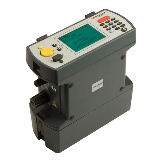
    ALLGEMEINE BESCHREIBUNG Beim DUCTER DLRO 10 und DUCTER DLRO 10X handelt es sich um Widerstandsmesser, die kleine Widerstände im Bereich von 0,1 µΩ bis 2kΩ messen. Beide Messgeräte stellen einen maximalen Prüfstrom von 10 Ampère Gleichstrom bereit, der automatisch in Abhängigkeit vom zu messenden Widerstand ausgewählt wird.
  • Seite 53: Bedienung - Dlro 10

    BEDIENUNG - DLRO 10 Anzeigen Leuchte Rauschen Spannung an “Kontak- Strom fließt Rauschen von mehr als 100 mV 50/60 Hz führt zum Einschalten der Prüfstrom Anschlüssen tausfall” Leuchte Rauschen; die Messgenauigkeit ist nicht verlässlich. Übermäßige Leuchten ‘C’ und ‘P’ Störung Die Leuchte ‘C’...
  • Seite 54: Bedienung - Dlro 10X

    BEDIENUNG - DLRO 10X TEST OPTIONS RANGE NORM NEXT TEST 1 STORED 27/07/00 12.02 Hauptmenü - DLRO 10X Obere Geräteplatte - DLRO 10X Nach dem Einschalten wird vom DLRO 10X ein Copyright-Hinweis und Alle Bedienelemente für Einstellung und Betrieb des DLRO 10X befinden dann das Hauptmenü...
  • Seite 55: Warnung Vor Externer Spannung

    BEDIENUNG - DLRO 10X Für eine gute Messung müssen sowohl der stromführende als auch Die Meldung “CURRENT FLOW” (Stromfluss) wird angezeigt, wenn der spannungsermittelnde Stromkreis über das Prüfobjekt geschlossen nach Abschluss einer Messung ein Strom von mehr als 1 mA fließt. Dies sein.
  • Seite 56: Retrieve" (Wiederaufruf)

    BEDIENUNG - DLRO 10X “Retrieve” (Wiederaufruf) “Download” (Herunterladen) Ermöglicht den Aufruf gespeicherter Messergebnisse zur Anzeige auf dem Bewirkt, dass der gesamte Inhalt des Datenspeichers über den RS232- Display oder auf einem PC. Anschluss links vom Display ausgegeben wird. Eine Kopie der Software “AVO Download Manager”...
  • Seite 57: Passbands " (Toleranzbänder)

    BEDIENUNG - DLRO 10X PASS (BESTANDEN) eingestellt, ebenso wie das Datumsformat. Bei Aufruf dieses Menüeintrags Die letzten drei Zeilen erscheinen nur, wenn Toleranzbänder eingerichtet werden aktuelles Datum und Uhrzeit sowie Datumsformat angezeigt. wurden. Mit den Cursortasten Auf und Ab einen markierten Wert abändern. Mit “Passbands “...
  • Seite 58: Delete Data" (Daten Löschen)

    BEDIENUNG - DLRO 10X “Delete Data” (Daten löschen) In manchen Fällen kann es allerdings wünschenswert sein, den maximalen Prüfstrom begrenzen zu wollen. In diesem Fall den Cursor auf den Die Option “Delete Data” auswählen, wenn im DLRO 10X gespeicherte gewünschten Prüfstromwert setzen und die Eingabetaste drücken. Daten gelöscht werden sollen.
  • Seite 59: Benutzung Der Tastatur

    BEDIENUNG - DLRO 10X Messungen enthalten, wobei jede durch ihre Nummer sowie Datum und stehen. Wird die Taste 2 beispielsweise einmal gedrückt, erscheint ein ‘A’, Uhrzeit identifiziert wird. wird sie zweimal gedrückt, erscheint ein ‘B’ usw. BENUTZUNG DER TASTATUR Die Taste 0 erbringt eine Leerstelle. Die Tastatur mit 12 Tasten ähnelt jener eines Mobiltelefons, insofern als Die Taste 1 ist die Rückschritt-Taste, mit der das davor stehende Zeichen über jede Taste einer von mehreren Buchstaben eingegeben werden kann,...
  • Seite 60 BEDIENUNG - DLRO 10X Schrägstrich Doppelpunkt Symbol “at” √ Häkchen Ausrufezeichen Fragezeichen “Dollar”-Symbol Gleichheitszeichen < Symbol “Kleiner als” > Symbol “Größer als” Sternchen...
  • Seite 61: Betriebsarten

    BETRIEBSARTEN Das DLRO 10 verfügt über fünf Betriebsarten für Messungen, die durch Betriebsart Kontinuierlich wiederholtes Drücken der Mode-Taste ausgewählt werden. Am Ende In der Betriebsart Kontinuierlich müssen die Anschlüsse hergestellt jeder Messung wird vom DLRO 10 der Mittelwert aus den Messungen mit worden sein, ehe die Messtaste gedrückt wird.
  • Seite 62: Einseitig Gerichteter Modus

    BETRIEBSARTEN Nach einer kurzen Zeit werden auf der Anzeige Widerstandswerte Einseitig gerichteter Modus erscheinen, die Ÿber eine gewisse Zeitspanne hinweg abfallen werden, bis Dieser Modus, der nur auf dem DLRO 10X vorhanden ist, stellt das eine stabile Anzeige erreicht ist. Gerät in den automatischen Modus, verwendet dabei aber lediglich Durchlaßstrom.
  • Seite 63: Vorgehen Bei Der Messung Und

    VORGEHEN BEI DER MESSUNG UND ANWENDUNG PRÜFEN MITTELS MIT KONTROLLLEUCHTEN AUSGESTATTETEN DUPLEX-MESSLEITUNGEN Da vom DLRO vor Anlegen des vollen Prüfstroms immer auf guten Jede Sondenschiene ist mit dem Buchstaben P gekennzeichnet. Dies Kontakt geprüft wird, kommt es zu keinem ‘Überschlag’, der die verweist auf die Potentialklemmen.
  • Seite 64: Einzelkabel

    1Ω verwenden oder beim DLRO 10X als maximalen Prüfstrom 1A im Bei Verwendung unter gefährlichen Spannungen müssen die DH6- Untermenü “Range” (Bereich) auswählen. Prüfkabel von Megger verwendet werden. ÜBERHITZUNG MESSABLAUF Bei Durchführung schnell wiederholter Messungen mit 10 A und unter Drücken der Messtaste startet den Messablauf.
  • Seite 65: Batteriemodul Und Pflege

    BATTERIEMODUL UND PFLEGE Hierdurch wird eine Batterie hoher Leistung und geringen Gewichts Ladegerät einstecken oder an eine 12 V Fahrzeugbatterie mit dem bereitgestellt, die jederzeit wieder aufgeladen werden kann. Die Batterie mitgelieferten Kabel mit ‘Zigarettenanzünder-Stecker’ anschließen. Die kann vom Benutzer weder übermäßig stark geladen noch entladen LED “Batterie-Ladezustand”...
  • Seite 66: Die Batterie-Ladezustandsanzeige

    BATTERIEMODUL UND PFLEGE Sch Bewegung DIE BATTERIE-LADEZUSTANDSANZEIGE Eingangsspannung zu niedrig. Die Batterie-Ladezustandsanzeige informiert über den Ladezustand der Das Ladegerät stellt dem Batteriemodul keine Batterie, gibt jedoch wie folgt auch über andere Zustände Auskunft: ausreichende Spannung für ein Laden der Batterie zur Verfügung. Standardladung.
  • Seite 67: Technische Daten

    TECHNISCHE DATEN Verfügung. Einzelheiten dazu sind im Zubehörteil dieser Bedienungsanleitung zu finden.“ Bereiche Volle Grösse Auflösung Genauigkeit Volle Grösse Volt Testpannung mit Widerstand induktiv mit Widerstand induktiv 1,9999 mΩ 0,1 µΩ ±0,2%±0,2 µΩ 20 mV 10 A 19,999 mΩ 1 µΩ ±0,2%±2 µΩ...
  • Seite 68 Meereshöhe max. 2000 m bei voller sicherheitstechnischer Spezifikation Sicherheit In Übereinstimmung mit IEC61010-1 600 V Kategorie III -Nur bei Verwendung von DH6-Prüfkabeln. Entsprïcht IEC61326-1 Betriebliche Unklarheiten Besuch www.megger.com Abmessungen 220 x 100 x 237 mm Gewicht 2.6 kg einschließlich Batteriemodul...
  • Seite 69: Fehlermeldung

    FEHLERSUCHE Fehlermeldung Störung Erforderliche Maßnahme bAtt Niedriger Ladezustand des Batteriemoduls. Batterie laden oder durch eine geladene ersetzen. _ _ _ _ _ Während der Messung trat ein Fehler auf, es wurde z.B. Richtigstellen und Messung wiederholen. der Kontakt an einer der Sonden verloren. ERR 114 Prüfsummenfehler im EEPROM.
  • Seite 70: Mit Dem Gerät Mitgeliefertes Standardzubehör

    ZUBEHÖR Mit dem Gerät mitgeliefertes Standardzubehör Waffelende 25940-014 7 Ah NiMH-Batteriemodul 6340-101 DLRO10LPU-EU-Netzstromanschluss — Schuko-Stecker 1003-172 Batterieladegerät für Betrieb ab 115/230 V 50/60 Hz- DLRO10LPU-UK-Netzstromanschluss — GB-Stecker 1003-093 DLRO10LPU-US-Netzstromanschluss — US-Stecker 1003-171 Vesorgung 6280-333 Adapter für Zigarettenanzünder für die Batterieladung 6280-332 Stromversorgungseinheit für das DLRO10LPU Benutzeranleitung...
  • Seite 71: Einzelkabell

    2,5 m/8 ft 6111-022 Stromklammern (2) für Stromanschlüsse 5,5 m/18ft 242011-18 2 m/7 ft 242041-7 6 m/20 ft 6111-023 5,5 m/18ft 242041-18 9 m/30 ft 242011-30 9 m/30 ft 242041-30 Gerade Duplex-Handspikes (2) schwere Normale Messleitungen am Inline-Anschluss nicht angebracht Ausführung mit festen 2 m/7 ft 242002-7...
  • Seite 72: Reparatur Und Garantie

    Wenn Sie Service-Ansprüche für Megger-Geräte haben, wenden Sie sich bitte an: EU-Konformitätserklärung Megger Limited oder Megger Hiermit erklärt Megger Instruments Limited, dass die von Megger Instru- Archcliffe Road Valley Forge Corporate Centre ments Limited produzierten und in dieser Anleitung beschriebenen Geräte Dover 2621 Van Buren Avenue mit der Richtlinie 2014/53/EU konform sind.
  • Seite 73 DLRO -10 & DLRO -10X ® ® Ohmmetro digitale a bassa resistenza GUIDA PER L’UTENTE...
  • Seite 74 INDICE Avvertenze di sicurezza Funzionamento della tastiera 83-84 La localizzazione dei guasti Descrizione generale Le modalita’ dei test Accessori Funzionamento generale - dlro 10 La modalità normale Gli indicatori di intensità Riparazioni e Garanzia La modalità automatica del test La modalità continua La spia luminosa del rumore 77 La modalità...
  • Seite 75: Avvertenze Di Sicurezza

    I terminali dello strumento saranno sotto tensione quando connessi al circuito. Quindi, quando si devona eseguire della prove in situazioni pericolose, si devono usare i cavi di prova modello DH6, DH6-C della Megger.
  • Seite 76: Descrizione Generale

    DESCRIZIONE GENERALE Il DUCTER DLRO 10 ed il DUCTER DLRO 10X costituiscono una famiglia di misuratori di ohm a bassa resistenza che misurano le resistenze nella gamma compresa tra 0.1 µΩ e 2kΩ. Entrambi gli strumenti provvedono una corrente massima del test di 10 Amp a corrente continua che è automaticamente selezionata in funzione del valore della resistenza che è...
  • Seite 77: Funzionamento Generale - Dlro

    FUNZIONAMENTO GENERALE - DLRO 10X Indicatori Tensione sui La spia luminosa del rumore “Guasto di Flusso di terminali Corrente di test contatto” corrente Il rumore superiore a 100 mV 50/60 Hz accenderà la spia luminosa ‘Noise’ Rumore (rumore) e la precisione della misura non può essere affidabile. eccessivo Gli indicatori ‘C’...
  • Seite 78: Funzionamento Generale - Dlro 10X

    FUNZIONAMENTO GENERALE - DLRO 10X rimanente della batteria, il numero di indice del prossimo test, il numero Controllo della retroilluminazione dei test già memorizzati e la data e l’orario correnti. Questo schermo da anche accesso al sistema di menu tramite il quale regolate il vostro strumento e scegliete i parametri del test desiderati.
  • Seite 79: Gli Indicatori 'C' E 'P

    FUNZIONAMENTO GENERALE - DLRO 10X Gli indicatori ‘C’ e ‘P’ Il sistema dei menu Una buona misura richiede che sia il circuito che trasporta la corrente Usate le frecce Sinistra e Destra del comando del cursore per mettere in che il circuito di scoperta della tensione siano completati dall’elemento risalto il menu richiesto.
  • Seite 80: Ritrova

    FUNZIONAMENTO GENERALE - DLRO 10X Ritrova Manager, che facilita lo scaricamento e formatta i dati. Permette di richiamare i risultati memorizzati sul display o su un PC. Io scaricamento dei dati non provoca la cancellazione dei dati Display memorizzati dalla memoria. Per cancellare i dati dalla memoria vedere “Cancellare i dati”...
  • Seite 81: Regolare L'orologio

    FUNZIONAMENTO GENERALE - DLRO 10X la media dei risultati dei test deve cadere se deve essere segnalata come un Successo (un tono lungo dal segnalatore acustico). Le letture esterne a questi limiti saranno segnalate come un Insuccesso (un tono breve dal segnalatore acustico).
  • Seite 82: Cancellare I Dati

    FUNZIONAMENTO GENERALE - DLRO 10X Regolare l’orologio. Comunque, i test già memorizzati prima di cambiare il programmato a AUTO, il DLRO 10X selezionerà l’intensità in base alla formato della data conserveranno il vecchio formato. resistenza che misura. (vedere Specificazioni, Gamme) Cancellare i dati Comunque, in alcuni casi può...
  • Seite 83: Memorizzare I Risultati Dei Test

    FUNZIONAMENTO GENERALE - DLRO 10X MEMORIZZARE I RISULTATI DEI TEST FUNZIONAMENTO DELLA TASTIERA Ogni test è numerato, a partire dal test 1. Questo numero di test si La tastiera a 12 tasti è simile a quelle usate sui telefoni cellulari in cui ogni incrementa automaticamente, appena ogni risultato è...
  • Seite 84 FUNZIONAMENTO GENERALE - DLRO 10X Nella modalità numerica una barra lampeggiante a mezza altezza (‘) indica Simbolo “Dollaro” il cursore. I tasti marcati 1 - 9 e lo 0 riproducono, quando premuti, quel Segno di “Uguale” numero. Premete il rispettivo tasto brevemente per inserire il numero desiderato.
  • Seite 85: Modalità Di Test

    MODALITÀ DI TEST LE MODALITA’ DEI TEST La modalità continua Il DLRO 10 ha cinque modalità dei test che sono selezionate premendo La modalità continua richiede che le connessioni siano fatte prima di ripetutamente il pulsante Mode (Modalità). Al termine di ogni test, il premere il pulsante Test.
  • Seite 86: La Modalità Unidirezionale

    MODALITÀ DI TEST Il tempo impiegato per ottenere un valore stabile può variare da qualche secondo a diversi minuti, in funzione dell’induttanza e della resistenza del campione di prova. Non esiste un limite per il controllo del valore d’induttanza, che continuerà fino a quando l’operatore provvede a premere il pulsante Prova.
  • Seite 87: Tecniche Dei Test E Applicazioni

    P è dentro le sonde C. La rimozione delle sonde farà spegnere la spia verde L2 (fine del Nota: Quando usato su tensioni pericolose Megger DH6 di prova deve test) e farà accendere quella rossa L1 (nessun contatto). essere utilizzato.
  • Seite 88: La Sequenza Dei Test

    TECNICHE DEI TEST E APPLICAZIONI LA SEQUENZA DEI TEST IL SURRISCALDAMENTO Premendo il pulsante TEST si avvia la sequenza dei test. Quando si realizzeranno rapidamente ripetuti test a 10 A, usando cavi di corrente con una resistenza combinata di 100 mΩ, si dissiperanno 10 W La resistenza del contatto è...
  • Seite 89: Il Modulo Della Batteria

    II MODULO DELLA BATTERIE E LA MANUTENZIONE Se la temperatura supera 45°C la velocità di caricamento sarà IL MODULO DELLA BATTERIA automaticamente ridotta. Il modulo della batteria contiene celle a Nichel-metallo-idruro e ha incorporato un sistema di gestione della batteria che controlla il Per caricare la batteria, il vostro modulo della batteria deve essere rimosso caricamento e lo scaricamento.
  • Seite 90: L'indicatore Di Stato Della Batteria

    II MODULO DELLA BATTERIE E LA MANUTENZIONE elevate). Verificate sempre l’indicatore di “Stato della batteria” prima di Caricamento standard ma ad un Lampeggiante Lento iniziare a lavorare. In una batteria completamente carica si illumineranno ritmo lento. tutti i segmenti. In una batteria completamente scarica non si illuminerà La batteria è...
  • Seite 91: Errore: Riazzerate

    II MODULO DELLA BATTERIE E LA MANUTENZIONE Lampeggia UNITÀ PER L’ALIMENTAZIONE DI RETE DLRO10LPU Errore: Riazzerate E’ avvenuto un errore nel modulo della DLRO10 e DLRO10X possono essere anche alimentati batteria. La circuiteria si sta risistemando. dall’unità per l’alimentazione di rete/alimentazione Aspettate qualche istante e l’errore elettrica DLRO10LPU.
  • Seite 92: Specificazioni

    SPECIFICAZIONI Gamme Valore Max Risoluzione Precisione Volt max Corrente di prova Resistiva Induttiva Resistiva Induttiva 1,9999 mΩ 0,1 µΩ ±0,2%±0,2 µΩ 20 mV 10 A 19,999 mΩ 1 µΩ ±0,2%±2 µΩ 20 mV 200 mV 199,99 mΩ 10 µΩ ±0,2%±20 µΩ 20 mV 200 mV 100 mA...
  • Seite 93 Sicurezza In conformità all IEC61010-1 600 V Categoria III - Solo quando DH6 prova porta sono utilizzati In accordo con IEC61326-1 Incertezze operative visita www.megger.com Dimensioni 220 x 100 x 237 mm (8.6 x 4 x 9.5 pollici) Peso 2.6 kg (53/4 libbre.) incluso il modulo della batteria...
  • Seite 94: La Localizzazione Dei Guasti

    LA LOCALIZZAZIONE DEL GUASTI Messaggio di errore Difetto Intervento necessario. bAtt Il modulo della batteria principale è debole. Ricaricate la batteria principale o sostituitela con una carica _ _ _ _ _ E’ avvenuto un errore durante la misurazione. Per Rettificate l’errore e ripetete la misura.
  • Seite 95: Accessori

    ACCESSORI Accessori standard in dotazione con lo strumento. DLRO10LPU-UK collegamento alla rete elettrica – spina UK 1003-093 DLRO10LPU-US collegamento alla rete elettrica – spina US 1003-171 Modulo batteria da NiMH da 7 Ah. 6340-101 Caricabatteria per funzionamento da 115/230 V. Conduttori di test opzionali a costo supplementare con fornitura da 50/60Hz.
  • Seite 96: Riparazioni E Garanzia

    RIPARAZIONI E GRANZIA Un numero di società indipendenti di riparazioni di strumenti è stato autorizzato a eseguire lavori sulla maggior parte degli strumenti Megger, Il circuito dello strumento contiene dispositivi sensibili alla statica, e usando parti di ricambio Megger originali. Consultare l’agente/distributore occorre fare attenzione a manipolare il pannello del circuito stampato.
  • Seite 97 Operation Declaración de conformidad Por la presente, Megger Instruments Limited declara que el equipo radioeléctrico fabricado por Megger Instruments Limited descrito en esta guía de usuario es conforme con la Directiva 2014/53/UE. Otros equipamientos fabricados por Megger Instruments Limited descritos en esta guía de usuario son conformes con las Directivas 2014/30/UE y 2014/35/UE donde son aplicables.
  • Seite 98 DUCTER DLRO -10 & DLRO -10X ® ® ® Ohmímetro digital de baja resistencia GUIA DEL USUARIO...
  • Seite 99 OPERATION Advertencias Funcionamiento del teclado 107-108 Reparación y Garantia Descripción general Modos de prueba Funcionamiento general - DLRO 10 Modo Normal Indicadores de corriente de prueba Modo Automático Lámpara de ruido Modo Continuo Indicadores ‘C’ & ‘P’ Modo de Alta Potencia Indicadores de aviso ‘V’...
  • Seite 100: Advertencias

    Los terminales del instrumento tendrán corriente cuando estén conectados al circuito. Por lo tanto cuando se usa en pruebas peligrosas de alto voltaje las pinzas Megger DH6, DH6-C deben ser utilizadas. La comprobación de los circuitos inductivos puede ser peligrosa: Después de probar una carga inductiva, habrá...
  • Seite 101: Descripción General

    DESCRIPCIÓN GENERAL LOSl INSTRUMENTOS DE MEDICIÓN DE RESISTENCIAS DLRO 10 y DLRO 10X constituyen una gama de ohmímetros de baja resistencia capaces de medir resistencias desde 0,1 µΩ hasta 2 kΩ. Ambos instrumentos ofrecen una corriente máxima de prueba de 10 amperios CC, que se selecciona automáticamente según el valor de la resistencia que se está...
  • Seite 102: Indicadores De Corriente De Prueba

    FUNCIONAMIENTO GENERAL - DLRO 10X Voltaje en Corriente Corriente Indicatorres de “fallo Lámpara de ruido bornes fluyendo de prueba de contacto” El ruido que sobrepase los 100 mV 50/60 Hz encenderá la lámpara de ‘Ruido’ y la precisión de la medición no será fiable. Ruido excesivo Indicadores ‘C’...
  • Seite 103: Panel Superior Del Dlro 10X

    FUNCIONAMIENTO GENERAL - DLRO 10X Panel superior del DLRO 10X Todos los controles necesarios para configurar y utilizar PRUEBA OPCIONES RANGO NORMAL SIGUIENTE PRUEBA 1 ALMACENADOS 27/07/00 12:02 Pantalla del menú principal del DLRO 10X Cuando se enciende por primera vez el DLRO 10X, se mostrará una pantalla de copyright, seguido por la pantalla del menú...
  • Seite 104: Ruido

    Funcionamiento general - DLRO 10X Advertencia de corriente de descarga Ruido El mensaje FLUJO DE CORRIENTE se mostrará si sigue pasando una El ruido que sobrepase los 100 mV 50/60 Hz activará el mensaje ‘Ruido’ corriente superior a 1 mA después de terminarse una prueba. Esto implica en la parte inferior de a pantalla.
  • Seite 105: Pantalla

    FUNCIONAMIENTO GENERAL - DLRO 10X Esta opción permite recuperar en la pantalla o en un PC los datos. los resultados almacenados. La descarga de los datos no ocasiona que los datos almacenados se borren de la memoria. Para borrar los datos de la memoria, consulte la sección “Eliminar datos”...
  • Seite 106: Bandas De Paso

    FUNCIONAMIENTO GENERAL - DLRO 10X Bandas de paso Ajustar reloj Esta opción le permite establecer límites superiores e inferiores entre los Esta opción ajusta la fecha y hora del reloj, así como el formato de fecha. que debe estar la media del resultado de prueba si se transmite como Cuando vaya a esta pantalla, se mostrará...
  • Seite 107: Eliminar Datos

    FUNCIONAMIENTO GENERAL - DLRO 10X Eliminar datos detecte (véase la sección Especificaciones, Rangos) Seleccione Eliminar datos si desea borrar los datos almacenados en la Sin embargo, en algunos casos puede ser necesario ajustar una corriente memoria del DLRO 10X. En caso de que haya seleccionado esta opción máxima de prueba.
  • Seite 108: Almacenamiento De Los Resultados De Prueba

    Funcionamiento general - DLRO 10X ALMACENAMIENTO DE LOS RESULTADOS DE PRUEBA FUNCIONAMIENTO DEL TECLADO Cada prueba está numerada, comenzando con la prueba 1. Este número El teclado de 12 teclas es similar al utilizado en los teléfonos móviles, ya de prueba se incrementa automáticamente a medida que se almacena que cada tecla permite introducir diferentes caracteres según el número cada resultado.
  • Seite 109 FUNCIONAMIENTO GENERAL - DLRO 10X La tecla en la esquina inferior derecha del teclado con un punto es una > Símbolo “mayor que” tecla especial que genera 20 símbolos especiales. Cada pulsación genera Asterisco sucesivamente el carácter mostrado a continuación: -. Punto decimal o punto ortográfico Ω...
  • Seite 110: Modos De Prueba

    TÉCNICAS DE PRUEBAS Y APLICACIONES MODOS DE PRUEBA Modo Continuo El DLRO 10 tiene 4 modos de prueba que se seleccionan pulsando varias El modo Continuo requiere que las conexiones se realicen antes de veces el botón Modo. Al final de cada prueba, el DLRO 10 mostrará la pulsar el botón Prueba.
  • Seite 111: Modo Unidireccional

    Técnicas de pruebas y aplicaciones cierto periodo de tiempo hasta que se obtiene una lectura estable. El tiempo requerido para obtener una lectura estable puede variar de unos segundos a varios minutos, dependiendo de la inductancia y resistencia de la muestra sometida a prueba. No hay un lìmite de tiempo para la prueba de modo inductivo, la cual continuará...
  • Seite 112 TÉCNICAS DE PRUEBAS Y APLICACIONES PRUEBAS CON CABLES DE PRUEBA DOBLES EQUIPADOS CON (final de prueba) y se encenderá la lámpara roja L1 LÁMPARAS INDICADORAS (no hay contacto). Cada barra está marcada con la letra P, que indica los terminales de Debido a que su DLRO garantiza siempre un buen contacto antes de potencial.
  • Seite 113: Secuencia De Prueba

    TÉCNICAS DE PRUEBAS Y APLICACIONES Nota: Cuando se usa en pruebas de alto voltaje las pinzas Megger DH6 SOBRECALENTAMIENTO deben ser utilizadas. Cuando realice pruebas repetidas rápidamente a 10 A con cables de corriente con una resistencia combinada de 100 mΩ, se disiparán 10 SECUENCIA DE PRUEBA W de calor en los cables y 30 W en su instrumento.
  • Seite 114: Módulo De Batería Y Cuidados

    MÓDULO DE BATERÍA Y CUIDADOS EL MÓDULO DE BATERÍA Para cargar la batería, debe extraerse el módulo de batería del instrumento. Extraiga el módulo presionando el área circular elevada de El módulo de batería contiene celdas de hidruro metálico de níquel e las abrazaderas de sujeción y saque la parte superior de la abrazadera incorpora un sistema de control de la batería que controla la carga y descarga.
  • Seite 115: Indicador De Estado De La Batería

    MÓDULO DE BATERÍA Y CUIDADOS no encenderá ningún segmento. caliente. Parpadeando Nota: todas las baterías tienen una vida útil reducida si se exponen Sin carga. Hay un problema de a temperaturas elevadas de forma constante. Una temperatura temperatura. constante de 30°C ocasionará probablemente que la batería dure La batería está...
  • Seite 116: Problema De Sobrevoltaje

    MÓDULO DE BATERÍA Y CUIDADOS Problema de sobrevoltaje El voltaje del suministro de carga es demasiado alto. Desconecte el cargador y solucione el fallo. AVISO La conexión a una fuente de tensión superior a 15 V puede causer dañor permanentes al módulo de baterías. La DLRO10 y la DLRO10X también se pueden alimentar desde la red eléctrica con la fuente de alimentación DLRO10LPU.
  • Seite 117: Especificaciones

    ESPECIFICACIONES Rangos Escala plena ResoluciÛn PrecisiÛn Voltios e escala plena Corriente de prueba Resistivo Inductivo Resistivo Inductivo 1,9999 mΩ 0,1 µΩ ±0,2%±0,2 µΩ 20 mV 10 A 19,999 mΩ 1 µΩ ±0,2%±2 µΩ 20 mV 20 mV 199,99 mΩ 10 µΩ ±0,2%±20 µΩ...
  • Seite 118 Según normativa IEC61010-1 600V Categoría III - Sólo cuando plomos de prueba DH6 son utilizados Compatibilidad electromagnética Conforme a IEC61326-1 Inexactitudes operacionales visita www.megger.com Dimensiones 220 x 100 x 237 mm (8,6 x 4 x 9,5 pulg.) Peso 2.6 kg (5...
  • Seite 119: Solución De Problemas

    SOLUCIÓN DE PROBLEMAS Mensaje de error Fallo Acción necesaria bAtt Bajo nivel de carga en el módulo de batería principal. Recargue la batería principal o sustitúyala con una batería cargada _ _ _ _ _ Se ha producido un error durante la medición, ej.: se Rectifique el error y repita la medición.
  • Seite 120: Accesorios

    ACCESORIOS Accesorios suministrados de serie con el instrumento DLRO10LPU-EU para la red eléctrica – conector schuko 1003-172 DLRO10LPU-UK para la red eléctrica – conector Reino Módulo de batería 7 Ah NiMH. 6430-101 Unido 1003-093 Cargador de batería para funcionar con suministro 115/230 V, 50/60Hz. 6280-333 DLRO10LPU-US para la red eléctrica –...
  • Seite 121 “handspikes” dúplex DH6 (2) adecuadas 2m/7 pies 242041-7 para funcionar en sistemas de 600 V. 2.5m/8pie 6111-518 5.5m/18pi 242041-18 9m/30pies 242041-30 “handspikes” dúplex (2) con contactos helicoidales accionados por resorte 2m/7 pies 242011-7 Los cables de prueba normales no caben en un conector en línea: 2.5m/8pie 6111-022 5.5m/18pi...
  • Seite 122: Reparación Y Garantia

    2014/30/UE e 2014/35/UE, ove applicabili. Fax: +44 (0) 1304 207342 Fax: +1 (610) 676-8625 Il testo integrale delle dichiarazioni di conformità UE di Megger o con una empresa de reparación aprobada. Instruments è disponibile all’indirizzo Internet seguente: megger.com/ eu-dofc.

Diese Anleitung auch für:

Dlro-10

Inhaltsverzeichnis