Inhaltsverzeichnis
Werbung
Verfügbare Sprachen
Verfügbare Sprachen
Werbung
Kapitel
Inhaltsverzeichnis

Verwandte Anleitungen für Camille Bauer SINEAX DME 406


Inhaltszusammenfassung für Camille Bauer SINEAX DME 406
- Seite 1 Betriebsanleitung SINEAX DME 406 Mode d’emploi SINEAX DME 406 Operating Instructions SINEAX DME 406 DME 406-1 Bd-f-e 02.14 Camille Bauer AG Aargauerstrasse 7 CH-5610 Wohlen/Switzerland Phone +41 56 618 21 11 Fax +41 56 618 21 21 info@camillebauer.com www.camillebauer.com...
- Seite 3 Betriebsanleitung Programmierbarer Multi-Messumformer mit PROFIBUS-DP Interface SINEAX DME 406 ................4 Mode d’emploi Convertisseur de mesure multiple programmable avec interface PROFIBUS-DP SINEAX DME 406 ................17 Operating Instructions Programmable multi-transducer with PROFIBUS-DP Interface SINEAX DME 406 ................30 Geräte dürfen nur fachgerecht entsorgt werden! Les appareils ne peuvent être éliminés que de façon appropriée!
-
Seite 4: Inhaltsverzeichnis
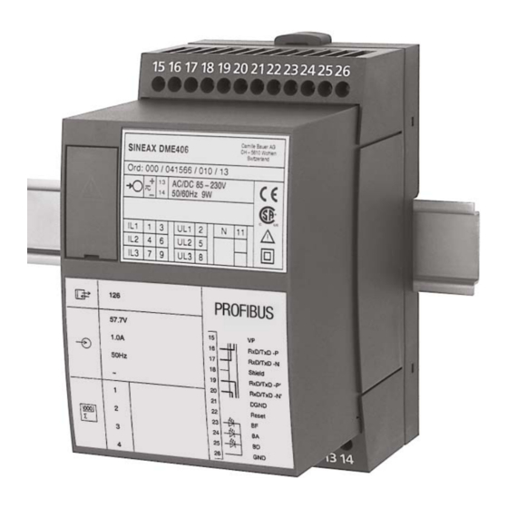
6. Befestigung ............... 10 7. Elektrische Anschlüsse ..........11 3. Kurzbeschreibung 8. Inbetriebnahme ............15 Der SINEAX DME 406 (Bild 1) ist ein programmierbarer 9. Wartung ..............15 Messumformer mit einem PROFIBUS-DP Interface zur 10. Demontage-Hinweis ..........15 gleichzeitigen Erfassung mehrerer Grössen eines elektrischen Starkstromnetzes. -
Seite 5: Bestellangaben
4. Bestellangaben 5. Technische Daten Eingang MERKMAL KENNUNG Kurvenform: Sinus 1. Bauform 406 - 1 Nennfrequenz: 50, 60 oder 16 2/3 Hz Gehäuse T24 für Schienen- und Wand- Eigenverbrauch [VA] Montage (bei externer 2. Nennfrequenz Hilfsenergie): Spannungspfad: U / 400 kΩ 50 Hz (60 Hz möglich ohne Zusatz- Strompfad: ≤... - Seite 6 Übertragungsverhalten Programmier-Anschluss am Messumformer Genauigkeitsklasse: 0,2 bzw. 0,4 bei Anwendungen mit Schnittstelle: RS 232 C Kunstschaltung DSUB-Buchse: 9-polig Energiezähler: 1,0 nach IEC 1036 (0,1 Ir ≤ I ≤ 1,5 Ir) Messzykluszeit: Je nach Messgrösse und Die Schnittstelle ist von allen ande- Programmierung ren Kreisen galvanisch getrennt.
-
Seite 7: Messgrössen, Die - Je Nach Anwendung - An Der Busschnittstelle Zur Verfügung Stehen
5.1 Messgrössen, die – je nach Anwendung – an der Busschnittstelle zur Verfügung stehen Tabelle 1: Anwendung Anwendung (siehe Tabelle 2) (siehe Tabelle 2) Sym- Sym- Erklärungen Erklärungen bole bole A24 / A24 / … … ● Eingangsspannung –– –– ●... -
Seite 8: Zurücksetzen
5.3 Programmierung des SINEAX DME 406 5.2 Zurücksetzen Der SINEAX DME 406 lässt sich auf zwei Arten program- – Reset der Energiezähler mieren: – Reset der Schleppzeiger 1) über RS 232, mit PC Software DME 4 2) über PROFIBUS-DP Interface mit GSD-Datei... - Seite 9 Fortsetzung der «Tabelle 2: Programmierung» Anwendung MERKMAL A11 … A16 A24 / A44 5. Energiezähler 1 Nicht belegt EA00 EA00 EA00 Netz [Ah] EA50 ––– ––– [Ah] ––– EA51 EA51 [Ah] ––– EA52 EA52 [Ah] ––– EA53 EA53 Netz [VAh] EA54 EA54 EA54...
-
Seite 10: Befestigung
6. Befestigung Die Befestigung des SINEAX DME 406 erfolgt wahlweise auf einer Hutschiene oder direkt an einer Wand bzw. auf einer Montagetafel. Bei der Bestimmung des Montageortes müs- sen die «Umgebungsbedingungen», Abschnitt «5. Technische Daten», eingehalten werden! 6.1 Montage auf Hutschiene Gehäuse auf Hutschiene (EN 50 022) aufschnappen (siehe... -
Seite 11: Elektrische Anschlüsse
7. Elektrische Anschlüsse Funktion Anschluss Messeingang Wechselstrom 1 / 3 4 / 6 7 / 9 Wechselspannung UL1 Frontseite RS 485 (PROFIBUS DP) RxD/TxD -P RxD/TxD -N Shield RxD/TxD -P’ RS 232 RxD/TxD -N’ DGND Hilfsenergie – Bei Hilfsenergie ab Spannungseingang erfolgt der interne Anschluss wie folgt: Anwendung (Netzform) Anschluss intern... - Seite 12 Messeingänge Netzformen / Klemmenbelegung Anwendung Dreileiter- Drehstromnetz gleichbelastet I: L1 (A13) Bei Strommessung über L2 bzw. L3, Spannungsanschluss nach folgender Tabelle vornehmen: Stromwandler Klemmen Dreileiter- Drehstromnetz gleichbelastet Kunstschaltung U: L1 – L2 I: L1 (A12) Bei Strommessung über L2 bzw. L3, Spannungsanschluss nach folgender Tabelle vornehmen: Stromwandler Klemmen Dreileiter-...
- Seite 13 Messeingänge Netzformen / Klemmenbelegung Anwendung Dreileiter- Drehstromnetz gleichbelastet Kunstschaltung U: L2 – L3 I: L1 Bei Strommessung über L2 bzw. L3, Spannungsanschluss nach folgender Tabelle vornehmen: (A16) Stromwandler Klemmen Vierleiter- Drehstromnetz gleichbelastet I: L1 (A14) Bei Strommessung über L2 bzw. L3, Spannungsanschluss nach folgender Tabelle vornehmen: Stromwandler Klemmen Dreileiter-...
- Seite 14 Messeingänge Netzformen / Klemmenbelegung Anwendung Vierleiter- Drehstromnetz ungleich- belastet (A44) 3 einpolig isolierte Spannungswandler im Hochspannungsnetz 9 11 Vierleiter- Drehstromnetz ungleich- belastet, Open-Y- Schaltung (A24) 2 einpolig isolierte Spannungswandler im Hochspannungsnetz Niederspannungsnetz Unterscheidung von PF, QF und LF Ausgang ind. kap.
-
Seite 15: Inbetriebnahme
Vor der Inbetriebnahme überprüfen, ob die Anschlussdaten des Messumformers mit den Daten der Anlage übereinstimmen (siehe Typenschild). Danach kann der Messumformer in Betrieb genommen werden. Camille Bauer AG SINEAX DME 406 CH - 5610 Wohlen Switzerland Ord: 146911/4444444 AC/DC 85…230 V 50/60Hz 10VA Bild 9... -
Seite 16: Sicherheitshinweise
Bedeutung der Symbole auf dem Gerät 12. Sicherheitshinweise Die Symbole auf dem Gerät haben folgende Bedeutung: ● Bevor das Gerät in Betrieb genommen wird, muss ge- prüft werden, für welche Hilfsenergiespannung das Gerät gebaut ist. ● Überzeugen Sie sich, dass die Anschlussleitungen nicht beschädigt und während der Verdrahtung des Gerätes Warnung vor einer Gefahrenstelle spannungsfrei sind. -
Seite 17: A Lire En Premier, Ensuite
Les caractéristiques de communication du convertisseur de mesure SINEAX DME 406 sont fi xées dans la forme d’un fi chier GSD (Gerätestammdaten-Datei = fi chier des caractéristiques de base de l’appareil) et déterminées par l’usine. -
Seite 18: Références De Commande
4. Références de commande 5. Caractéristiques techniques Entrée CARACTERISTIQUE DESIGNATION Forme de la courbe: Sinusoïdale 1. Construction 406 - 1 Fréquence nominale: 50, 60 ou 16 2/3 Hz Boîtier T24 pour montage sur rail ou Consommation propre [VA] sur paroi (avec alimentation 2. - Seite 19 Caractéristiques de transmission Connecteur de programmation du convertisseur de mesure Classe de protection: 0,2 resp. 0,4 en application avec phase artifi cielle Interface: RS 232 C Compteur d’énergie: 1,0 selon CEI 1036 Douille DSUB: 9-pôles (0,1 Ir ≤ I ≤ 1,5 Ir) Durée du cycle de mesure: Selon grandeur mesurée et pro-...
-
Seite 20: Grandeurs De Mesure Disponibles - Selon L'application - Au Bus Informatique
5.1 Grandeurs de mesure disponibles – selon l’application – au bus informatique Tableau 1: Application (voir tableau 2) Application Sym- (voir tableau 2) Signifi cation bole Sym- A24 / Signifi cation … bole A24 / … ● ● ● Fréquence de la grandeur ●... -
Seite 21: Remise À Zéro
5.3 Programmation du SINEAX DME 406 5.2 Remise à zéro La programmation du SINEAX DME 406 peut être réalisée – Remise à zéro des compteurs d’énergie de deux façons différentes: – Remise à zéro de la fonction d’aiguille entraînée 1) par RS 232, avec logiciel PC DME 4 2) par interface PROFIBUS-DP avec fi... - Seite 22 Suite du «Tableau 2: Programmation» Application CARACTERISTIQUE A11 … A16 A24 / A44 5. Compteur d’énergie 1 Non utilisé EA00 EA00 EA00 Réseau [Ah] EA50 ––– ––– [Ah] ––– EA51 EA51 [Ah] ––– EA52 EA52 [Ah] ––– EA53 EA53 Réseau [VAh] EA54 EA54...
-
Seite 23: Fixation
6. Fixation Les SINEAX DME 406 peuvent être au choix montés sur des rails «à chapeau» ou directement sur une surface de montage. En déterminant l’emplacement de montage, il faut tenir compte des indications fournis sous le rubrique «Ambiance extérieure» du chapitre «5. -
Seite 24: Raccordements Électriques
7. Raccordements électriques Fonction Connexion Entrée de Courant alternatif 1 / 3 mesure 4 / 6 7 / 9 Tension alternative UL1 Face avant RS 485 (PROFIBUS DP) RxD/TxD -P RxD/TxD -N Shield RxD/TxD -P’ RS 232 RxD/TxD -N’ DGND Alimentation CA auxiliaire –... - Seite 25 Entrées de mesure Réseau / Disposition des bornes Application Courant triphasé 3 fils à charges équilibrées I: L1 (A13) Pour la mesure du courant en L2 resp. L3, connecter les tensions selon tableau ci-après: Transformateur Bornes du courant Courant triphasé 3 fils à...
- Seite 26 Entrées de mesure Réseau / Disposition des bornes Application Courant triphasé 3 fils à charges équilibrées Phase artificielle Pour la mesure du courant en L2 resp. L3, connecter les tensions selon tableau ci-après: U: L2 – L3 I: L1 Transformateur Bornes (A16) du courant...
- Seite 27 Entrées de mesure Réseau / Disposition des bornes Application Courant triphasé 4 fils à charges dés- équilibrées (A44) 3 transformateurs de tensions unipolaires isolés pour réseau haute tension 9 11 Courant triphasé 4 fils à charges dés- équilibrées Open-Y- connection (A24) 2 transformateurs de tensions unipolaires isolés pour réseau haute tension...
-
Seite 28: Mise En Service
(voir plaquette signalétique). Ensuite, le convertisseur de mesure peut être mise en service. Camille Bauer AG SINEAX DME 406 CH - 5610 Wohlen Switzerland Ord: 146911/4444444 AC/DC 85…230 V Fig. 9... -
Seite 29: Consignes De Sécurité
Signifi cation des symboles fi gurant sur l’appareil 12. Consignes de sécurité Les symboles fi gurant sur l’appareil signifi ent: ● Avant de mettre l’appareil en service, vérifi er pour quelle tension d’alimentation auxiliaire il a été conçu. ● S’assurer que les câbles de connexion ne soient pas endommagés et qu’ils soient sans tension lors du rac- cordement de l’appareil. -
Seite 30: Read Fi Rst And Then
7. Electrical connections ..........37 8. Commissioning ............41 3. Brief description 9. Maintenance .............. 41 SINEAX DME 406 (Fig. 1) is a programmable transducer with 10. Releasing the transducer .......... 41 a PROFIBUS-DP Interface that simultaneously measures 11. Dimensional drawings ..........41 several variables of a heavy-current power systems. -
Seite 31: Ordering Information
4. Ordering information 5. Technical data Input DESCRIPTION MARKING Waveform: Sinusoidal 1. Mechanical design 406 - 1 Rated frequency: 50, 60 or 16 2/3 Hz Housing T24 for rail and wall mounting Consumption [VA] 2. Rated frequency (at external power supply): Voltage circuit: U / 400 kΩ... - Seite 32 Programming connector on transducer System response Interface: RS 232 C Accuracy class: 0.2 resp. 0.4 at applications with phase-shift DSUB socket: 9-pin Energy meter: 1.0 according to IEC 1036 (0.1 Ir ≤ I ≤ 1.5 Ir) Duration of the The interface is electrically insula- measurement cycle: Depending on measured variable ted from all other circuits.
-
Seite 33: Measured Values That Are Available At The Bus Interface, Depending On The Application
5.1 Measured values that are available at the bus interface, depending on the application Table 1: Application Application (see table 2) (see table 2) Sym- Sym- Meaning Meaning bols A24 / bols A24 / … … Input voltage ● –– ––... -
Seite 34: Resetting
5.3 Programming the SINEAX DME 406 5.2 Resetting There are two ways to confi gure the SINEAX DME 406: – Energy meter reset 1) via RS 232, with PC software DME 4 – Maximum value pointer reset 2) via PROFIBUS-DP Interface with DBF fi le... - Seite 35 Continuation “Table 2: Programming” Application DESCRIPTION A11 … A16 A24 / A44 5. Energy meter 1 Not used EA00 EA00 EA00 System [Ah] EA50 ––– ––– [Ah] ––– EA51 EA51 [Ah] ––– EA52 EA52 [Ah] ––– EA53 EA53 System [VAh] EA54 EA54 EA54...
-
Seite 36: Wall Mounting
6. Mounting The SINEAX DME 406 can be mounted either on a top-hat rail or directly onto a wall or mounting surface. Note “Environmental conditions” in Section “5. Technical data” when determining the place of installation! 6.1 1 Mounting on top-hat rails Simply clip the device onto the top-hat rail (EN 50 022) (see Fig. -
Seite 37: Electrical Connections
7. Electrical connections Function Connection Measuring input AC current 1 / 3 4 / 6 7 / 9 AC voltage Front RS 485 (PROFIBUS DP) RxD/TxD -P RxD/TxD -N Shield RxD/TxD -P’ RS 232 RxD/TxD -N’ DGND Power supply AC –... - Seite 38 Measuring inputs System / Terminals application 3-wire 3-phase symmetric load I: L1 (A13) Connect the voltage according to the following table for current measurement in L2 or L3: Current transf. Terminals 3-wire 3-phase symmetric load Phase-shift U: L1 – L2 I: L1 Connect the voltage according to the following table for current measurement in L2 or L3: (A12)
- Seite 39 Measuring inputs System / Terminals application 3-wire 3-phase symmetric load Phase-shift U: L2 – L3 Connect the voltage according to the following table for current measurement in L2 or L3: I: L1 (A16) Current transf. Terminals 4-wire 3-phase symmetric load I: L1 (A14) Connect the voltage according to the following table for current measurement in L2 or L3:...
- Seite 40 Measuring inputs System / Terminals application 4-wire 3-phase asymmetric load (A44) 3 single-pole insulated voltage transformers in high-voltage system 9 11 4-wire 3-phase asymmetric load, Open-Y connection (A24) 2 single-pole insulated voltage transformers in high-voltage system Low-voltage system Relationship between PF, QF and LF Output cap.
-
Seite 41: Commissioning
(see type label). The power supply to the transducer can then be switched on and the signals applied to the measuring inputs. Camille Bauer AG SINEAX DME 406 CH - 5610 Wohlen Switzerland Ord: 146911/4444444 AC/DC 85…230 V 50/60Hz 10VA Fig. -
Seite 42: Safety Notices
Meaning of the symbols on the device 12. Safety notes The symbols on the device have the following meaning: ● Before you start the device check for which power supply it is built. ● Verify that the connection leads are in good condition and that they are electrically dead while wiring the device.