
Verwandte Anleitungen für IFM Electronic LR7022


Inhaltszusammenfassung für IFM Electronic LR7022
- Seite 1 Bedienungsanleitung Operating instructions Notice d’utilisation Elektronischer Füllstandsensor Electronic level sensor Capteur de niveau électronique LR70...
-
Seite 2: Inhaltsverzeichnis
Inhalt Bestimmungsgemäße Verwendung ..... . 3 Funktionsbeschreibung ....... 3 Montage . -
Seite 3: Bestimmungsgemäße Verwendung
Bestimmungsgemäße Verwendung Einsatzbereich LR70 ist ein kompakter Füllstandsensor für die Erfassung flüssiger Medien. Das Gerät wurde speziell für die Bedürfnisse des Werkzeugmaschinenbaus konzipiert. Es ist insbesondere geeignet für die Überwachung von Kühlschmieremulsionen sowie von wasser- basierten Reinigungsflüssigkeiten in Anlagen zur Teilereinigung. Beschränkung des Einsatzbereichs •... -
Seite 4: Funktionsübersicht
Funktionsübersicht • Das Gerät zeigt den aktuellen Füllstand im Display an und signali- siert das Erreichen oder Unterschreiten eingestellter Grenzen über zwei Schaltausgänge. Höhe Schaltpunkte Rückschaltpunkte und die Schaltfunktionen der Ausgänge lassen sich über das Bedienmenü einstellen. Für jeden der beiden Schaltausgänge kann eine Rückschaltverzögerung (max. -
Seite 5: Montage
Montage Sie haben 3 Montagemöglichkeiten: 1. Einschrauben in einen Prozessanschluss G¾ im Behälterdeckel. 2. Einbau in den Behälterdeckel mit Hilfe einer Flanschplatte (z. B. bei dünnwandigen Behältern). 3. Einbau in einen offenen Behälter mit Hilfe einer Halterung. ACHTUNG: Das Gerät benötigt in jedem Fall eine metallische Fläche zum Einkoppeln der Messsignale (Einkoppelplatte). - Seite 6 Zu 3: Bei Einbau in offene Metallbehälter muss das Gerät mit Hilfe einer metallischen Halterung montiert werden. Sie dient als Einkoppelplatte (R). Mindestgröße: 150 x 150 mm bei einer quadratischen Halterung, 150 mm Durchmesser bei einer kreisförmigen Halterung. Montieren Sie das Gerät möglichst mittig auf der Halterung. Der Abstand D2 darf 40 mm nicht unterschreiten.
- Seite 7 • Bei nicht geraden Behälterwänden, Absätzen, Verstrebungen oder sonstigen Einbauten muss ein Abstand von 50 mm zur Behälterwand eingehalten werden. • Bei Einbau in Rohren muss der Rohr-Innendurchmesser (d) minde- stens 100 mm betragen. Verwenden Sie ausschließlich metallische Rohre. • Bei Einbau in Stutzen muss der Durchmesser des Stutzens (d) min- destens 50 mm betragen.
- Seite 8 Anpassen des Sondenstabes Die Geräte werden mit unter- schiedlich langen Sondenstäben (L) geliefert: LR7022: L = 240 mm LR7023: L = 450 mm LR7024: L = 700 mm Die Sondenstäbe können Anpassung an unterschiedliche Behälterhöhen gekürzt werden. Die minimal zulässige Stablänge Lmin beträgt 150 mm.
- Seite 9 Einbau des Geräts mit Hilfe einer Flanschplatte • Für den Einbau des Geräts benötigen Sie eine Bohrung im Behälterdeckel. Die Bohrung muss einen Mindestdurchmesser (d) haben, um eine ausreichende Einkopplung des Messsignals auf den Sondenstab zu ermöglichen. Der Durchmesser hängt ab von der Wandstärke des Behälterdeckels: Wandstärke [mm] 1...5...
-
Seite 10: Elektrischer Anschluss
Elektrischer Anschluss Das Gerät darf nur von einer Elektrofachkraft installiert werden. Befolgen Sie die nationalen und internationalen Vorschriften zur Errichtung elektrotechnischer Anlagen. Spannungsversorgung nach EN50178, SELV, PELV. Schalten Sie die Anlage spannungsfrei; schließen Sie das Gerät folgendermaßen an: Pin / Belegung Adernfarben bei ifm-Kabeldosen braun OUT2 (Arbeitsschaltausgang) -
Seite 11: Programmieren
Programmieren Drücken Sie die Taste Mode/Enter, bis der gewünschte Parameter Mode/Enter Set im Display erscheint. Drücken Sie die Taste Set und halten Sie sie gedrückt. Mode/Enter Set Der aktuelle Parameterwert wird 5 s lang blinkend angezeigt, danach wird er erhöht* (schrittweise durch Einzeldruck oder kontinuierlich durch Festhalten der Taste). -
Seite 12: Bedien- Und Anzeigeelemente
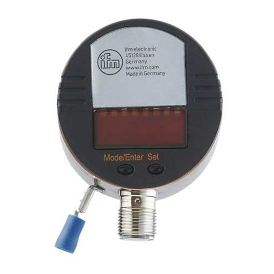
Bedien- und Anzeigeelemente Leuchtende LED = eingestellte Anzeigeeinheit: 2 x LED grün - LED 1 = Anzeige des Füllstands in cm. - LED 2 = Anzeige des Füllstands in inch. Anzeige des Schaltzustands; leuchtet, wenn der jeweilige Ausgang durchgeschaltet ist. 2 x LED gelb - LED 1 = OUT1 (frei konfigurierbarer Ausgang). - Seite 13 Menü-Übersicht...
- Seite 14 Führen Sie zur Programmierung die folgenden Schritte in der angegebenen Reihenfolge durch. Schritt Programmiervorgang Parameter Erweiterte Funktionen aufrufen • Taste Mode/Enter drücken, bis EF im Display erscheint. • Taste Set drücken. Im Display erscheint nun der erste Parameter des erweiterten Menüs. Durch erneutes Drücken der Taste Set rufen Sie den zugehörigen Parameterwert auf.
- Seite 15 Schritt Programmiervorgang Parameter Einstellen der Schaltparameter SP1: Schaltpunkt 1 = oberer Grenzwert, bei dem Schaltausgang OUT1 seinen Schaltzustand ändert. rP1: Rückschaltpunkt 1 = unterer Grenzwert, bei dem Schaltausgang OUT1 seinen Schaltzustand ändert. OU1: Schaltfunktion für Schaltausgang OUT1. Es sind 4 Einstellungen wählbar: Hysterese- (H..) oder Fensterfunktion (F..);...
- Seite 16 Zubehör lieferbar. Einstellbereiche für OFS (gilt für alle Geräte des Typs LR70) inch Einstellbereich 0...100 0...39,4 Schrittweite Einstellbereiche für SPx, rPx LR7022 ( L = 24)* LR7023 (L = 45)* LR7024 ( L = 70)* inch inch inch 1,5...20,0 0,6...7,8 1,5...41,0 0,6...16,2...
- Seite 17 Hysteresefunktion (Hno, Hnc) (Abb. 1): Die Hysterese hält den Schaltzustand des Ausgangs stabil, wenn der Prozesswert um den Sollwert schwankt. Bei steigendem Prozesswert schaltet der Ausgang bei Erreichen des Schaltpunkts (SPx). Fällt der Prozesswert wieder ab, schaltet der Ausgang erst dann zurück, wenn der Rückschaltpunkt rPx unterschrit- ten wird.
-
Seite 18: Inbetriebnahme / Betrieb
Inbetriebnahme / Betrieb Prüfen nach Montage, elektrischem Anschluss Programmierung, ob das Gerät sicher funktioniert. Betriebs- und Fehleranzeigen: Initialisierung nach dem Einschalten. XX.X Anzeige des Füllstands. Während des Betriebs: Füllstand unterhalb des aktiven Bereichs. Während der Programmierung: Rückmeldung beim Werks-Reset: Alle Parameter zurückgesetzt auf Werkseinstellung. FULL Maximaler Messbereich ist erreicht oder überschritten. -
Seite 19: Einstellung Der Parameter Ablesen
Einstellung der Parameter ablesen: • Kurzer Druck auf die Taste “Mode/Enter” blättert durch die Parameter. • Kurzer Druck auf die Taste “Set” zeigt jeweils 15 s lang den zugehörigen Parameterwert ohne ihn zu verändern. Ausgangsverhalten in verschiedenen Betriebszuständen OUT1 OUT2 Initialisierung gemäß... -
Seite 20: Applikationen
Applikationen Mindestfüllstand-Überwachung mit Vorwarnung und Alarm Schaltausgang 1: Vorwarnung Geringfügig über rP1 (um Wellenbewegungen auszublenden) Soll-Füllstand unterschritten → Vorwarnung, Nachfüllen starten Hysteresefunktion, Öffner (Hnc) Schaltausgang 2: Alarm Min-Wert wieder erreicht → Alarm zurückgesetzt Min-Wert unterschritten → Alarm Hysteresefunktion, Schließer (Hno) Vorwarnung Alarm OUT1... - Seite 21 Applikationen Hebeanlage Behälter entleeren mit Überfüllsicherung Schaltausgang 1: Regelung Behälter entleeren Oberer Normalwert überschritten → Tauchpumpe EIN Unterer Normalwert erreicht → Tauchpumpe AUS Hysteresefunktion, Schließer (Hno) Schaltausgang 2: Überfüllsicherung Maximalwert überschritten → Alarm Geringfügig unter SP2 (um Wellenbewegungen auszublenden) Hysteresefunktion, Öffner (Hnc) Überfüll- Entleeren sicherung...
- Seite 22 Applikationen Vorlage- bzw. Druckerhöhungsbehälter Gutbereich-Überwachung (Alarm) und Regelung des Füllstands Schaltausgang 1: Nachfüllen Oberer Sollwert erreicht → Nachfüllen beenden Unterer Sollwert unterschritten → Nachfüllen starten Hysteresefunktion, Öffner (Hnc) Schaltausgang 2: Sicherheitfunktion Min-Max Max-Wert überschritten → Alarm Min-Wert unterschritten → Alarm Fensterfunktion, Schließer (Fno) Min- Max-...
-
Seite 23: Maßzeichnung
Maßzeichnung LR7022 LR7023 LR7024 inch inch inch L (Stablänge) 17,7 27,6 A (aktiver Bereich) 15,8 25,6 (inaktiver Bereich 1) (inaktiver Bereich 2) 4-stellige alphanumerische Anzeige Status-LEDs Programmiertasten... -
Seite 24: Safety Instructions
Contents Function and features ........25 Functional overview ........25 Mounting . -
Seite 25: Function And Features
Function and features Applications LR70 is a compact level sensor for the detection of liquids. The unit was specially designed to meet the requirements of machine tool building. It is specially suited for monitoring coolant emulsions as well as aqueous cleaning agents in part cleaning systems. Restriction of the application area •... - Seite 26 Functional overview • The unit displays the current level and signals via two switching out- puts that the set limits have been reached or that the level is below the set limit. The setpoint and reset point values and the switching function of the outputs can be set via the user menu.
-
Seite 27: Mounting
Mounting There are 3 mounting options: 1. Screw in a G¾ process connection in the tank lid. 2. Installation in the tank lid using a flange plate (e.g. for tanks with thin walls). 3. Installation in an open tank using a fixture. ATTENTION: In all cases the unit needs a metal surface to transfer the measured signals (transfer plate). - Seite 28 On 3: For installation in open metal tanks, the unit must be mounted using a metal fixture. It serves as a transfer plate (R). Minimum size: 150 x 150 mm for a square fixture, 150 mm diameter for a circular fixture. If possible, mount the unit in the middle of the fixture.
- Seite 29 • For tank walls which are not straight, steps, supports or other struc- tures in the tank a distance of 50 mm to the tank wall must be adhered to. • For installation in pipes the inside pipe diameter (d) must be min. 100 mm.
- Seite 30 Adaptation of the probe The sensors are supplied with probes in different lengths (L): LR7022: L = 240 mm LR7023: L = 450 mm LR7024: L = 700 mm The probes can be shortened to adapt to different tank heights.
- Seite 31 Installation of the sensor using a flange plate • For installation of the unit you need a bore hole in the tank lid. The bore hole must have a minimum diameter (d) to enable sufficient transfer of the measured signal to the probe. The diameter depends on the wall thickness of the tank lid: Wall thickness [mm] 1...5...
-
Seite 32: Electrical Connection
Electrical connection The unit must be connected by a suitably qualified electrician. The national and international regulations for the installation of electrical equipment must be observed. Voltage supply according to EN50178, SELV, PELV. Disconnect power before connecting the unit as follows: Pin / connection core coloursof ifm sockets brown... -
Seite 33: Programming
Programming Press the Mode/Enter button several times until the respective Mode/Enter Set parameter is displayed. Press the Set button and keep it pressed. The current parameter Mode/Enter Set value flashes for 5 s, then the value is increased* (incremental by pressing briefly or scrolling by holding pressed). -
Seite 34: Controls And Indicating Elements
Controls and indicating elements Lighting LED = set display unit: 2 x LED green - LED 1 = level in cm. - LED 2 = level in inch. Switching status indication; lights if the respective output is switched. 2 x LED yellow - LED 1 = OUT1 (freely configurable output). -
Seite 35: Menu Structure
Menu structure... - Seite 36 For programming carry out the following steps in the indicated order. Step Programming Parameter Access the extended functions • Press the Mode/Enter button until EF is displayed. • Press the Set button. The first parameter of the extend- ed menu is now displayed. You can access the corre- sponding parameter value by pressing the Set button again.
- Seite 37 Step Programming Parameter Setting of the switching parameters SP1: setpoint 1 = upper limit value at which the switch- ing output OUT1 changes its switching status. rP1: reset point 1 = lower limit value at which the switch- ing output OUT1 changes its switching status. OU1: switching function for the switching output OU1.
- Seite 38 Setting range for OFS (applies to all LR70 type units) inch Setting range 0...100 0...39.4 in steps of Setting range for SPx, rPx LR7023 (L = 45)* LR7024 ( L = 70)* LR7022 ( L = 24)* inch inch inch 1.5...20.0 0.6...7.8 1.5...41.0 0.6...16.2 1.5...66.0 0.6...26.0 1.0...19.5 0.4...7.6...
- Seite 39 Hysteresis function (Hno, Hnc) (fig. 1): The hysteresis keeps the switching state of the output stable if the level of the medium varies about the preset value. With the level rising, the output switches when the switch-on point has been reached (SPx). With the level falling, the output does not switch back until the level falls below the reset point rPx.
-
Seite 40: Installation And Set-Up / Operation
Installation and set-up / Operation After mounting, wiring and programming check whether the unit operates correctly. Operating and fault indication: Initialisation after power on. XX.X Level indication. During operation: level below the active zone. During programming: Feedback during factory reset: all parameters reset to factory setting". -
Seite 41: Output Response In Different Operating States
Read the set parameter values: • The parameter names are scrolled with each pressing of the "Mode/Enter" button. • When the "Set" button is pressed briefly, the corresponding para- meter value is displayed for 15 s. Output response in different operating states OUT1 OUT2 Initialisation... -
Seite 42: Applications
Applications Minimum level monitoring with prewarning and alarm Switching output 1: prewarning slightly above rP1 (to suppress wave movements) below preset level → prewarning, start refilling hysteresis function, normally closed (Hnc) Switching output 2: alarm min. value reached again → alarm reset below min. - Seite 43 Applications Pumping station Empty the vessel with overflow protection Switching output 1: control to empty vessel upper value exceeded → submersible pump ON lower value reached → submersible pump OFF hysteresis function, normally open (Hno) Switching output 2: overflow protection maximum value exceeded →...
- Seite 44 Applications Storage vessel Monitoring of the acceptable range (alarm) and level control Switching output 1: refilling upper preset value reached → finish refilling below lower preset value → start refilling hysteresis function, normally closed (Hnc) Switching output 2: safety function min - max max.
-
Seite 45: Scale Drawing
Scale drawing LR7022 LR7023 LR7024 inch inch inch L = probe length 17.7 27.6 A = active zone 15.8 25.6 (inactive zone 1) (inactive zone 2) 4-digit alphanumeric display LEDs Programming buttons... - Seite 46 Contenue Fonctionnement et caractéristiques ......47 Aperçu des fonctions ........47 Montage .
-
Seite 47: Fonctionnement Et Caractéristiques
Fonctionnement et caractéristiques Application LR70 est un capteur de niveau compact pour la détection de liquides. L'appareil a été conçu pour satisfaire notamment aux exigences des applications en machines-outils. Il est particulièrement approprié pour contrôler les liquides d'arrosage et de lubrification ainsi que d'autres détergents aqueux dans les systèmes de nettoyage de pièces. -
Seite 48: Aperçu Des Fonctions
Aperçu des fonctions • L'appareil affiche le niveau actuel et signale à l'aide de deux sorties de commutation que les valeurs limites réglées sont atteintes ou que le niveau est inférieur à la valeur limite réglée. Les points de consigne haut et bas, et les fonctions de commutation des sorties peuvent être réglés via le menu utilisateur. -
Seite 49: Montage
Montage Vous avez 3 possibilités de montage : 1. Montage par un raccord process G ¾ dans le couvercle de la cuve. 2. Montage dans le couvercle à l'aide d'une bride à visser (p. ex. en cas de cuves aux parois minces) 3. - Seite 50 Concernant 3 : En cas de montage dans des cuves métalliques ouvertes, l'appareil doit être monté à l'aide d'une fixation métallique. Elle sert de plaque de transmission (R). Dimensions minimales : 150 x 150 mm en cas d'une fixation carrée, 150 mm diamètre en cas d'une fixation circulaire. Monter l'appareil au milieu de la fixation autant que possible.
- Seite 51 • En cas de parois de la cuve non planes, de crans, d'entretoises ou d'autres éléments présents dans la cuve, une distance de 50 mm avec la paroi de la cuve doit être respectée. • En cas de montage dans des tuyaux, le diamètre intérieur (d) du tuyau doit être au moins 100 mm.
- Seite 52 Adaptation de la sonde Les capteurs sont livrés avec des sondes de différentes longueurs (L). LR7022: L = 240 mm LR7023: L = 450 mm LR7024: L = 700 mm La sonde peut être raccourcie pour l'adapter aux différentes hauteurs de cuves. La longueur minimale admissible de la sonde Lmin est de 150 mm.
- Seite 53 Montage du capteur à l'aide d'une bride à visser • Pour le montage de l'appareil, un trou percé dans le couvercle de la cuve est nécessaire. Le trou percé doit avoir un diamètre minimal (d) pour permettre une transmission suffisante du signal de mesure dans la sonde.
-
Seite 54: Raccordement Électrique
Raccordement électrique L'appareil doit être monté par un électricien. Les règlements nationaux et internationaux relatifs à l'installation de matériel électrique doivent être respectés. Alimentation selon EN50178, TBTS, TBTP. Mettre l'installation hors tension avant de raccorder l'appareil comme suit : Couleurs des fils conducteurs des Broche / raccordement connecteurs femelles ifm : brun... -
Seite 55: Programmation
Programmation Appuyer sur le bouton Mode/Enter plusieurs fois jusqu'à ce que le Mode/Enter Set paramètre désiré soit affiché. Appuyer sur le bouton Set et le maintenir appuyé. Mode/Enter Set La valeur de paramètre actuelle clignote pendant 5 s, après la valeur est incrémentée* (pas à... -
Seite 56: Eléments De Service Et D'indication
Eléments de service et d'indication LED allumée = unité sélectionnée : 2 x LED verte - LED 1 = niveau en cm. - LED 2 = niveau en inch. Indication de l'état de commutation, LED allumée si la sortie correspondante est commutée. 2 x LED jaune - LED 1 = OUT1 (sortie à... -
Seite 57: Structure Du Menu
Structure du menu... - Seite 58 Pour la programmation, effectuer les étapes suivantes dans l'ordre indiqué. Programmation Paramètre Accéder aux fonctions étendues • Appuyer sur le bouton-poussoir Mode/Enter jusqu'à ce que EF soit affiché. • Appuyer sur le bouton-poussoir Set. Le premier paramètre du menu étendu est maintenant affiché. En appuyant encore une fois sur le bouton-poussoir Set vous accédez à...
- Seite 59 Programmation Paramètre Réglage des paramètres de commutation SP1 : seuil 1 = valeur limite maximale à laquelle la sortie de commutation OUT1 change son état de commutation. rP1 : seuil 1 = valeur limite minimale à laquelle la sortie de commutation OUT1 change son état de commutation.
- Seite 60 Plages de réglage pour OFS (s'applique à tous les appareils de type LR70). inch Plage de réglage 0...100 0...39,4 en pas de Plages de réglage pour SPx, rPx LR7022 ( L = 24)* LR7023 (L = 45)* LR7024 ( L = 70)* inch inch inch 1,5...20,0 0,6...7,8...
- Seite 61 Fonction hystérésis (Hno, Hnc) (fig. 1) : L'hystérésis garantit un état de commutation stable de la sortie en cas de fluctuations du niveau du fluide autour de la valeur présélec- tionnée. Si le niveau augmente, la sortie commute lorsque la consigne haute est atteinte (SPx).
-
Seite 62: Mise En Service / Fonctionnement
Mise en service / Fonctionnement Après le montage, le raccordement électrique et la programmation, vérifier le bon fonctionnement de l'appareil. Indication de fonctionnement et de défauts : Initialisation après la mise sous tension. XX.X Indication du niveau. Durant le fonctionnement : niveau en-dessous de la zone active. Durant la programmation et avec la fonction rES : signalisation : tous les paramètres remis aux valeurs réglées en usine. -
Seite 63: Données Techniques
Lecture des valeurs de paramètres réglées : • Si le bouton-poussoir "Mode / Enter" est appuyé brièvement, les paramètres sont parcourus. • Si le bouton-poussoir "Set" est appuyé brièvement, la valeur de paramètre correspondante est indiquée pendant env. 15 s. Comportement de la sortie en différents modes de fonctionnement OUT1... -
Seite 64: Applications
Applications Surveillance du niveau minimal avec pré-alarme et alarme Sortie de commutation 1 : pré-alarme faiblement supérieur à rP1 (pour supprimer les mouvements de vagues) au-dessous du niveau présélectionné → pré-alarme, commencer le remplissage fonction hystérésis, normalement fermé (Hnc) Sortie de commutation 2 : alarme valeur minimale atteinte de nouveau →... - Seite 65 Applications Système de pompage Vider une cuve avec protection contre le débordement Sortie de commutation 1 : régulation vider une cuve valeur normale supérieure dépassée → pompe submersible EN MARCHE valeur normale inférieure atteinte → pompe submersible ARRET fonction hystérésis, normalement ouvert (Hno) Sortie de commutation 2 : protection contre le débordement valeur maximale dépassée →...
- Seite 66 Applications Cuve de stockage Surveillance de la plage acceptable (alarme) et régulation du niveau Sortie de commuation 1 : remplissage valeur préselectionnée supérieure atteinte → terminer le remplissage au-dessous de la valeur préselectionnée inférieure → commencer le remplissage fonction hystérésis, normalement fermé (Hnc) Sortie de commutation 2 : fonction de sécurité...
-
Seite 67: Dimensions
Dimensions LR7022 LR7023 LR7024 inch inch inch L (longueur de la sonde) 17,7 27,6 A (zone active) 15,8 25,6 (zone non active 1) (zone non active 2) Visualisation alphanumérique à 4 digits LEDs Boutons-poussoirs...