Dynacord H 2500 Bedienungsanleitung
Inhaltsverzeichnis
Verfügbare Sprachen
Verfügbare Sprachen
Inhaltsverzeichnis

Verwandte Anleitungen für Dynacord H 2500


Inhaltszusammenfassung für Dynacord H 2500
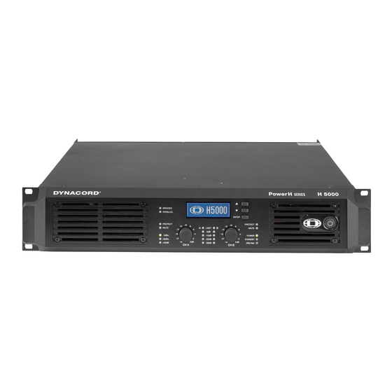
- Seite 1 H 2500 | H 5000 PowerH SERIES Amplifier Owner‘s Manual | Bedienungsanleitung | Mode d‘emploi...
- Seite 46 PowerH SERIES Owner’s Manual...
- Seite 47 Regelungen zur WEEE-Umsetzung in den einzelnen EU-Staaten bitten wir Sie, sich an Ihren örtlichen Händler zu wenden. Wir haben ein eigenes System zur Verarbeitung elektronischer Abfälle und gewährleisten die kostenfreie Entgegennahme aller Produkte der EVI Audio GmbH: Telex, Dynacord, ElectroVoice, Midas Consoles, KlarkTeknik und RTS.
-
Seite 48: Einführung
PowerH SERIES 1 Einführung 1.1 Willkommen Mit den neuen Endstufen der PowerH SERIES von Dynacord beginnt ein neues Zeitalter in der Endstufen- Technologie. Die hocheffiziente PowerH-Endstufe liefert kompromisslose Audioperformance bei geringem Gewicht und höchster Zuverlässigkeit. Durch optionale Remote-Control-Module ist die vollständige Kontrolle und Überwachung der Endstufe über die PC Software IRIS-Net möglich. -
Seite 49: Eigenschaften & Beschreibung
PowerH SERIES 1.4 Eigenschaften & Beschreibung Die Endstufe H2500/H5000 gehört zur neuen PowerH SERIES von Dynacord, die einen Meilenstein in Design und Produktion von Hochleistungs-Endstufen darstellt. Die innovative 3-stufige Grounded Bridge Class H Topologie mit „Floating“ Schaltnetzteil bietet eine sehr hohe, stabile Ausgangsleistung bei sehr hohem Wirkungsgrad auf extrem hohem Performance-Niveau und dabei äußerst geringem Gewicht. -
Seite 50: Installation
PowerH SERIES 2 Installation 2.1 Bedienelemente, Anzeigen und Anschlüsse Frontseite Abbildung 2.1: H2500/H5000 Frontseite LC-Display (mit Bedienelementen) Anzeige Stummschaltung (MUTE) für Kanal A bzw. B Anzeige Schutzschaltung (PROTECT) für Kanal A bzw. B Eingangspegel-Regler (CH A, CH B) für Kanal A bzw. B Pegelanzeige für Kanal A bzw. -
Seite 51: Rückseite
PowerH SERIES Rückseite Abbildung 2.2: H2500/H5000 Rückseite Netzeingang PowerCon (MAINS IN) Endstufenausgangsbuchsen Speakon (CH A, CH B) Endstufenausgangsklemmen (CHANNEL A, CHANNEL B, BRIDGED) Erweiterungssteckplatz Audioeingänge XLR und Phoenix (IN A, IN B) Schalter Eingangsempfindlichkeit/Gain Schalter Betriebsart Audioeingänge (ROUTING) Lüfter Schalter Betriebsart Endstufenausgänge (MODE) Audioausgänge XLR (OUT A, OUT B) Schalter Groundlift (CIRCUIT ... -
Seite 52: Werkseinstellungen
Wert Power-On-Delay 0.00 s Breaker Current (abhängig vom Leitungsnetz) 16 A (230 V) / 30 A (120 V) Amplifier Name Dynacord H2500 bzw. Dynacord H5000 LCD Contrast LCD Brightness High LCD Brightness Low LCD Time to Dim Autodim off Temperature Unit °C... -
Seite 53: Netzbetrieb & Wärmeentwicklung In Der Endstufe
PowerH SERIES Trennen Sie die Endstufe während der Installation immer von der Netzversorgung. Schließen Sie die Endstufe nur an eine geeignete Netzversorgung an, die den auf dem Typenschild angegebenen Anforderungen entspricht. Abbildung 2.3: H2500/H5000 Typenschild Gerät Spannung Netzfrequenz Leistungsaufnahme H2500 100-240 V 50-60 Hz 1000 W... -
Seite 54: Netzschalter
PowerH SERIES H5000 in V in A in W in W in W BTU/hr mains mains mains Idle 24.5 4089 2 x 1500 1089 3716 Max. Output Power @ 8 40.9 7137 2 x 2500 2137 7292 Max. Output Power @ 4 18.1 2927 2 x 833... -
Seite 55: Einbau
PowerH SERIES 2.4 Einbau Vordere Befestigung der Endstufe Die PowerH-Endstufe wurde für den Einbau in ein konventionelles 19-Zoll Rack entwickelt. Befestigen Sie die Endstufe an der Vorderseite mit 4 Schrauben und Unterlegscheiben wie in Abbildung 2.4 dargestellt. Abbildung 2.4: Vordere Befestigung der Endstufe bei Rackeinbau Hintere Befestigung Wird das Rack, in dem die Endstufe eingebaut ist, transportiert, muss die Rückseite der Endstufe im Rack befestigt werden. -
Seite 56: Kühlung
PowerH SERIES 2.5 Kühlung allen lüftergekühlen Endstufen Dynacord strömt die Luft von der Frontseite zur Rückseite, da kühle Frischluft eher außerhalb des Racks zur Verfügung steht als innerhalb. Die Endstufe bleibt kühler und die entstehende Abwärme kann gezielter abgeführt werden. -
Seite 57: Wahl Der Betriebsart
PowerH SERIES Stellung BRIDGED des Schalters MODE gewählt ist. Bei Schalterstellung NORMAL leuchtet die BRIDGED-LED nicht. 2.8 Wahl der Betriebsart ROUTING Der Schalter ROUTING an der Rückseite der Endstufe bestimmt die Schaltung der Audioeingänge. DUAL In der Betriebsart DUAL arbeiten beide Kanäle der Endstufe unabhängig voneinander. Diese Betriebsart wird bei allen 2-kanaligen Anwendungen wie Stereobetrieb oder Bi-Amp (Aktivbetrieb) verwendet. - Seite 58 PowerH SERIES MODE Der Schalter MODE an der Rückseite der Endstufe bestimmt die Betriebsart der Endstufenblöcke und damit wie ein oder mehrere Lautsprecher angeschlossen werden müssen. NORMAL Im Zweikanalbetrieb (NORMAL) arbeiten beide Endstufenblöcke als unabhängige Endstufenkanäle. Die Verstärkung jedes Kanals kann separat geregelt werden. Die Schaltung der Audio-Eingänge der Endstufe ist nur von der Stellung des Schalters ROUTING abhängig.
-
Seite 59: Audio Verkabelung
PowerH SERIES Eine Eingangsempfindlichkeit von 0dBu bedeutet, dass bei einem Eingangssignal von 0 dBu (0.775 V am Endstufenausgang die Nennleistung (Rated Output Power) abgegeben wird. Diese Einstellung empfiehlt sich bei Signalquellen, die eine nominale Spannung von 0 dBu liefern. Alternativ kann die Endstufe auch mit einer festen Verstärkung (Constant Gain) von 35 dB oder 32 dB betrieben werden. -
Seite 60: Ausgang (Speakon / Anschlussklemmen) Im Normal Mode
PowerH SERIES Zusätzlich zu den Eingängen steht für jeden Kanal jeweils eine parallel geschaltete XLR-Buchse (OUT A bzw. OUT B) zur Verfügung. Über diese kann das Audiosignal komfortabel zu anderen Geräten weitergeführt werden (Daisy-Chain). 1, SHIELD 3, COLD 2, HOT Abbildung 2.12: Symmetrische Beschaltung des Ausgang (Daisy-Chain) Ausgang (Speakon / Anschlussklemmen) im Normal Mode Der Anschluss von Lautsprechern an die PowerH-Endstufe unterscheidet sich je nach gewählter... -
Seite 61: Ausgang (Speakon / Anschlussklemmen) Im Bridged Mode
PowerH SERIES Neben den Speakon-Buchsen stehen für den Anschluss von Lautsprechern auch Anschlussklemmen zur Verfügung. In der Betriebsart NORMAL werden die Lautsprecher entsprechend folgender Abbildung angeschlossen. Abbildung 2.14: Lautsprecheranschluss in Betriebsart NORMAL an Anschlussklemmen Bi-Amp Verkabelung Die zweite Möglichkeit zum Anschluss von Lautsprechern an die Endstufe in der Betriebsart NORMAL ist die alleinige Verwendung der Speakon-Buchse CH A. - Seite 62 PowerH SERIES Speakon CH A Anschluss Belegung Bridged+ Bridged- Tabelle 2.7: Lautsprecheranschluss in Betriebsart BRIDGED an Speakon A An den Anschlussklemmen wird in der Betriebsart BRIDGED der Lautsprecher zwischen den roten Klemmen von CHANNEL A und CHANNEL B angeschlossen. Die korrekte Anschlussweise für diese Betriebsart ist zusätzlich auf der Endstufe selbst abgebildet.
-
Seite 63: Betrieb
PowerH SERIES 3 Betrieb 3.1 Volume Control In den Betriebsarten DUAL und PARALLEL regeln die Levelsteller CH A bzw. CH B an der Frontseite der Endstufe die Verstärkung des jeweiligen Kanals. Drehung nach rechts erhöht die Lautstärke, Drehung nach links verringert die Lautstärke. In der Betriebsart BRIDGED regelt nur der Drehknopf CH A die Lautstärke der Endstufe. -
Seite 64: Menüführung Endstufe
PowerH SERIES Menüführung Endstufe Nach dem Einschalten der Endstufe wird der Startbildschirm mit der Typenbezeichnung der Endstufe angezeigt. Nach einigen Sekunden wird die Statusanzeige der Endstufe dargestellt. In der obersten Zeile wird immer die Bezeichnung der Endstufe angezeigt. Die zweite und dritte Zeile liefert einen Überblick über den aktuellen Zustand der Endstufe. -
Seite 65: Status Display
PowerH SERIES Folgende Abbildung stellt die Struktur des Menüs CONFIG (und der zugehörigen Untermenüs) ausgehend von der Statusanzeige dar. Mit * markierte Menüeinträge sind nur dann verfügbar, wenn kein Remote Control Modul eingebaut ist. Status display Power-On-Delay DISPLAY SETUP EVENT LOG LCD Contrast Breaker Current Counter POWER UP... - Seite 66 PowerH SERIES Menüstruktur CONFIG Das Konfigurationsmenü CONFIG erreicht man durch Drücken der ENTER-Taste bei Anzeige des Eintrags >> CONFIG << im Statusdisplay. Nachfolgend sind die einzelnen Einträge des Konfigurationsmenüs erläutert. CONFIG.Power-On-Delay: Es wird die momentan eingestellte Einschaltverzögerung der Endstufe angezeigt. Durch Drücken der ENTER-Taste gelangt man in den Dialog Set Power-On-Delay.
- Seite 67 PowerH SERIES CONFIG.Menu Display: Der Menüeintrag Menu Display führt in das Untermenü DISPLAY SETUP. Die einzelnen Einträge des Menüs DISPLAY SETUP sind im Abschnitt Menüstruktur CONFIG.DISPLAY SETUP (siehe Seite 69) erläutert. CONFIG.Menu Service: Der Menüeintrag Menu Service führt in das Untermenü SERVICE. Die einzelnen Einträge des Menüs SERVICE sind im Abschnitt Menüstruktur CONFIG.SERVICE (siehe Seite 70) erläutert.
- Seite 68 PowerH SERIES Menüstruktur CONFIG.EVENT LOG CONFIG.EVENT LOG.Counter POWER UP: Es wird die Anzahl der Betätigungen des Netzschalters an der Frontseite angezeigt. CONFIG.EVENT LOG.Counter AMP ON: Es wird die Anzahl der Aktivierungen der Endstufe, sowohl aus dem Zustand Aus als auch aus dem Zustand Standby, angezeigt.
- Seite 69 PowerH SERIES CONFIG.EVENT LOG.Reset Event Log: Das Event Log der Endstufe kann komplett zurückgesetzt werden. Durch das Rücksetzen werden alle Zähler auf Null gesetzt und die Ereignisliste wird gelöscht. Durch Drücken der ENTER-Taste gelangt man zu einer Sicherheitsabfrage. In der Sicherheitsabfrage kann durch Drücken der Up/Down-Tasten zwischen YES und NO gewählt werden.
- Seite 70 PowerH SERIES CONFIG.DISPLAY SETUP.LCD Time to Dim: Es wird die momentan eingestellte Beleuchtungsdauer Displays angezeigt. Nach Ablauf dieser Zeitdauer wird die Displaybeleuchtung zurückgedimmt. Durch Drücken der ENTER-Taste gelangt man in den Dialog Set LCD Time to Dim. Im Dialog Set Time to Dim kann durch Drücken der Up/Down- Tasten Zeitdauer Dimmvorgang...
- Seite 71 Endstufe (ohne Standby-Zeit) an. CONFIG.SERVICE.Last Log: Es wird Zeitpunkt und Art des letzten Eintrags im Event Log angezeigt. Der angezeigte Code kann im Fehlerfall Ihrem Dynacord Service-Partner nähere Hinweise auf die genaue Fehlerursache geben. CONFIG.SERVICE.Module Signature: Falls ein Remote-Control Modul eingebaut ist, können die angezeigten Informationen im Fehlerfall Ihrem Dynacord Service-Partner nähere Hinweise auf...
- Seite 72 PowerH SERIES Menüstruktur MODULE CONFIG Alle Einstellmöglichkeiten am Remote-Control-Modul RCM-26 über das LC-Display der Endstufe sind in einem eigenen Menü MODULE CONFIG zusammengefasst. Dieses Menü ist während des Betriebs der Endstufe nicht zugänglich. Der Zugang zu diesem Menü ist nur von der ausgeschalteten Endstufe aus möglich.
- Seite 73 PowerH SERIES MODULE CONFIG.Preset: Es wird die Bezeichnung des momentan aktiven Presets angezeigt. Durch Drücken der ENTER- Taste gelangt man in den Dialog Load Preset. Im Dialog Load Preset kann durch Drücken der Up/Down- Tasten zwischen den verschiedenen Presets gewählt werden. Drücken der ENTER-Taste führt zu einer Sicherheitsabfrage, ob das Preset wirklich geladen werden soll.
-
Seite 74: Anzeigen
PowerH SERIES MODULE CONFIG.DSP Mute: Es wird angezeigt ob die Endstufe momentan stummgeschaltet (Mute) oder nicht stummgeschaltet (Unmute) ist. Durch Drücken der ENTER-Taste gelangt man in den Dialog Set DSP Mute. Im Dialog Set DSP Mute kann durch Drücken der Up/Down-Tasten die Stummschaltung aktiviert (Mute) bzw. -
Seite 75: Lüfter
PowerH SERIES ein, der den weiteren Anstieg des Klirrfaktors zuverlässig auf 1 % begrenzt. Die dabei rot aufleuchtende LIMIT-LED verfügt über eine dynamische Helligkeitssteuerung, wodurch leicht abzulesen ist, wie weit sich das Signal in der Begrenzung befindet. POWER Die POWER-LED leuchtet grün auf, wenn die Endstufe eingeschaltet ist. Falls die POWER-LED trotz eingeschaltetem Gerät nicht leuchtet, ist das Gerät entweder nicht mit dem Stromnetz verbunden, die Primärsicherung defekt, oder die Endstufe befindet sich im Standby-Modus (STANDBY-LED leuchtet gelb). -
Seite 76: Schutzschaltungen
PowerH SERIES 3.5 Schutzschaltungen Wenn während des Betriebs der Endstufe eine der integrierten Schutzschaltungen anspricht, wird im LC- Display eine entsprechende Meldung angezeigt bzw. die PROTECT-LED des betroffenen Kanals leuchtet auf. Zusätzlich wird im Event-Log ein Eintrag mit Datum, Uhrzeit und Art der Schutzschaltung angelegt. True RMS Mains Voltage and Current Measurement Endstufen der PowerH SERIES sind permanent über den Zustand des speisenden Netzes informiert. -
Seite 77: Power-On Delay Und Softstart
PowerH SERIES Die CPU der Endstufe kennt den zeitlichen Verlauf des aufgenommenen Netzstromes und kann damit das Verhalten eines typischen Netzsicherungsautomaten simulieren. In den Impulsspitzen werden dabei durchaus Spitzenströme zugelassen, die ein Mehrfaches des Nennwertes überschreiten können. Durch die Effektivwertmessung des aufgenommenen Netzstromes kann die CPU die Temperatur des Thermoauslösers eines Sicherungsautomaten nachbilden. - Seite 78 PowerH SERIES Limitation ausgeführt. Hierbei erfolgt eine Einschränkung der internen Versorgungsspannung der Endstufenblöcke. Dies geht zwar objektiv mit einer Verringerung der Spannungsdynamik einher, ist jedoch bei Musik- oder Sprachsignalen subjektiv kaum wahrnehmbar. Trotz der kaum vorhandenen akustischen Beeinflussung ist der erreichte Effizienzgewinn in der Endstufe so hoch, dass die Wärmeentwicklung deutlich reduziert wird.
-
Seite 79: Optionen
PowerH SERIES 4 Optionen Durch den Einbau eines optionalen Zusatzmoduls in den Erweiterungssteckplatz an der Rückseite kann der Funktionsumfang der Endstufe erhöht werden. Als Beispiel wird im folgenden das RCM-26 Remote Control Modul aufgeführt. Bitte beachten Sie bei allen Zusatzmodulen die jeweils mitgelieferte Bedienungsanleitung. -
Seite 80: Umbau Von Pre-Fader- Auf Post-Fader-Betriebsart
PowerH SERIES Der analoge Audioeingang erreicht eine Dynamik von 120 dB, ebenfalls ein absoluter Spitzenwert für digitale Audiogeräte. Sämtliche Details zur Konfiguration, Steuerung und Überwachung von Endstufen mit eingebauten RCM-26 Modulen sind in der Dokumentation der Software IRIS-Net enthalten. Installationshinweise Einbau 1. - Seite 81 PowerH SERIES Abbildung 4.2: Jumperstellung in Pre-Fader-Betriebsart (links) und Post-Fader-Betriebsart (rechts) IRIS-Net Zur Konfiguration und Bedienung eines Remote Amplifiers mit RCM-26 wird die PC-Software IRIS-Net (Intelligent Remote & Integrated Supervision) verwendet. gesamte Konfiguration des RCM-26 kann hierbei offline auf dem PC erstellt werden. In den Hilfe- Dateien von IRIS-Net finden Sie sämtliche Hinweise für die Konfiguration, Bedienung und Überwachung aller RCM-26 Funktionen.
-
Seite 82: Bedienelemente Und Anschlüsse
PowerH SERIES Bedienelemente und Anschlüsse Abbildung 4.4: Bedienelemente und Anschlüsse des RCM-26 1 AES/EBU-IN Neben den internen Analogeingängen steht ein digitaler AES/EBU Eingang (AES3) zur Verfügung. Das digitale Eingangssignal wird Buchse AES/EBU angeschlossen. Es handelt sich um einen symmetrischen Eingang mit Übertrager zur galvanischen Isolierung. Über einen Sample-Rate-Converter wird das Signal an die interne Abtastrate angepasst. - Seite 83 PowerH SERIES 3 LOCK-LED Die LOCK-LED leuchtet grün, wenn der AES/EBU-Eingang auf das empfangene Signal synchronisiert ist und die Audioübertragung in Ordnung ist. Wenn die LOCK-LED nicht leuchtet, liegt entweder kein digitales Audiosignal an, oder die interne PLL ist nicht auf das ankommende Signal eingrastet.
- Seite 84 PowerH SERIES Abbildung 4.7: Belegung der CAN-Buchse Abbildung 4.8: Belegung des CAN-Steckers Kabelfarbe nach Name T568A T568B CAN_GND Grün Orange CAN_H (+) Blau CAN_L (-) Blau gestreift MONITOR BUS + Braun gestreift MONITOR BUS - Braun Tabelle 4.2: Übersicht CAN-Stecker 5 STATUS LED Die STATUS-LED dient zur Kontrolle der Kommunikation am CAN-Bus.
- Seite 85 PowerH SERIES Die Adresse 0 (00 hex, Auslieferungszustand) sorgt dafür, dass das RCM-26 von der Remote- Kommunikation getrennt ist. Das Modul erscheint somit nicht im System, auch wenn es am CAN-Bus angesteckt ist. Wird eine Endstufe mit einem auf 0 adressiertem RCM-26 eingeschaltet, werden sämtliche internen Parameter auf 0 bzw.
-
Seite 86: Remote-Control-Netzwerk
PowerH SERIES 8 RS-232 Schnittstelle Die RS-232 Schnittstelle dient der Verbindung des RCM-26 mit Mediensteuerungssystemen bzw. Gebäudemanagementsystemen. Über RS-232 können sämtliche Parameter gesteuert und abgefragt werden. Die Kommunikation erfolgt über ein einfach zu implementierendes ASCII-Protokoll. Programmierhinweise und eine vollständige Protokollbeschreibung sind in der IRIS-Net-Dokumentation enthalten. - Seite 87 PowerH SERIES Da die CAN-Schnittstelle in allen EVI Audio Geräten galvanisch getrennt von den übrigen Schaltungsteilen aufgebaut ist, wird auch eine gemeinsame Masseleitung (CAN_GND) in der Netzwerkverkabelung mitgeführt (siehe folgende Abbildung). Damit ist sichergestellt, dass alle CAN-Schnittstellen im Netzwerk auf einem gemeinsamen Potential liegen. Abbildung 4.10: CAN-Bus mit Linien-Topologie Durch einen CAN-Bus-Repeater kann eine Verbindung zwischen zwei unabhängigen und in sich abgeschlossenen CAN-Bus-Systemen hergestellt werden.
-
Seite 88: Systembeispiele
PowerH SERIES Systembeispiele Die folgenden beiden Abbildungen zeigen Beispiele von Systemverdrahtungen eines Remote-Control- Netzwerks. Zur Verbindung des Remote-Control-Netzwerks mit einem PC wird jeweils ein USB-CAN- Converter verwendet. Abbildung 4.11: 5 Remote-Amplifier (mit RCM-26) und ein USB-CAN-Converter am Bus-Anfang. Ab- schluss-Stecker am USB-CAN-Converter und am RCM-26 des Remote-Amplifier 5 Abbildung 4.12: System mit 2 Racks und einem USB-CAN-Converter. - Seite 89 PowerH SERIES Leitungsspezifikation Gemäß dem ISO 11898-2 Standard sollten für den CAN-Bus als Datenübertragungskabel vorzugsweise Twisted-Pair-Leitungen, geschirmt oder ungeschirmt, mit einem Wellenwiderstand von 120 zum Einsatz kommen. Als Leitungsabschluss muss an beiden Enden ein Abschlusswiderstand von 120 vorgesehen werden.
- Seite 90 PowerH SERIES Bedienungsanleitung...
-
Seite 139: Dimensions / Abmessungen
PowerH SERIES Dimensions / Abmessungen...