Werbung
Verfügbare Sprachen
Verfügbare Sprachen
Quicklinks
UV 300 UNIVERSAL-VORVERSTÄRKER
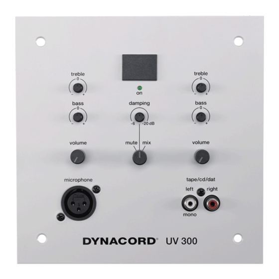
Wandpanel zum Anschluß eines Mikrofons und einer NF-Signalquelle an eine ELA-Anlage.
1. Kurze Beschreibung, technische Daten
Ein Mikrofoneingang (XLR-Buchse) mit Bass-,
Treble- und Lautstärkesteller
Ein Line-Eingang (Cinch-Buchsen) mit Bass-,
Treble- und Lautstärkesteller
Line-Eingang auf Damping- oder Mixfunktion
schaltbar
(Schlüssel)-Taster/Schalter zum Ferneinschalten
der Anlage nachrüstbar
LED-Anzeige (grün): Anlage ein
Phantomspannung (+18V) für die Mikrofonbuchse
über Jumper steckbar
Kaskadierungseingang zum Koppeln von bis zu
5 UV 300 Modulen
Mute (Stummschaltung) des kompletten Panels
Technische Daten
Eingänge:
Ausgänge:
MIC (XLR - Buchse 3pol)
LINE (Cinch - Buchse mono l und r)
Kaskadierungseingang intern: (8-pol. Klemmleiste)
intern: Summenausgang
(elektr.-symmetrisch, optional Übertrager)
Stromversorgung
Stromaufnahme
Zul. Umgebungstemperatur
Abmessungen (mm)
Gewicht
Fremdspannung
Geräuschspannung
Klirrfaktor
Nachrüstsätze:
Symm. Ausgang
5mV / Ze = 1.4 kOhm
(2mV / 8.5mV, jumperbar)
775mV / Ze = 48 kOhm
(155mV, jumperbar)
0dBu/ Ze = 34 kOhm
0dBu/+6dBu
24V=
60mA
+5°C...+40°C
170x170x50
480g
UF = 30 mV = -88dBu
Ug = 65 mV = -81dBu
k £ 0,02 %
NRS-Nr. 90189
Werbung

Inhaltszusammenfassung für Dynacord UV 300
- Seite 1 Anlage nachrüstbar LED-Anzeige (grün): Anlage ein Phantomspannung (+18V) für die Mikrofonbuchse über Jumper steckbar Kaskadierungseingang zum Koppeln von bis zu 5 UV 300 Modulen Mute (Stummschaltung) des kompletten Panels Technische Daten Eingänge: MIC (XLR - Buchse 3pol) 5mV / Ze = 1.4 kOhm (2mV / 8.5mV, jumperbar)
- Seite 2 Die 3 Schaltstellungen dieses Mode-Schalters bedeuten: mute - das Modul UV 300 ist stummgeschaltet, das NF-Ausgangs- signal ist von der ELA-Anlage abgekoppelt. damping - in dieser Schaltstellung beeinflußt das Mikrofonsignal die Laut- stärke des NF-Signals des Cinch-Eingangs, abhängig von der Stellung des Damping-Reglers.
- Seite 3 (Wird mit dem Ausgang eines weiteren Modulsverbunden) 4. Bedienung des UV 300 Sobald die Anlage eingeschaltet ist, leuchtet die ON LED des UV 300 und zeigt damit an, daß das Modul betriebsbe- reit ist. An der Buchse “microphone” kann nun ein Mikrofon und /oder an der Buchse tape/cd/dat eine andere Tonquelle (Kas- settendeck, Tuner..) angeschlossen werden.
- Seite 4 5. Jumpereinstellungen auf der Printplatte (Standardkonfiguration = fettgedruckt); X bedeutet: Jumper gesteckt Jumper Steckplatz Steckplatz Funktion Die Eingangsempfindlichkeit beträgt 2mV Die Eingangsempfindlichkeit beträgt 5mV Die Eingangsempfindlichkeit beträgt 8,5mV Der Ausgangspegel des Moduls beträgt 0dB Der Ausgangspegel des Moduls beträgt +6dB Die Eingangsempfindlichkeit beträgt 155mV Die Eingangsempfindlichkeit beträgt 775mV Die Pantomspannung ist abgeschaltet...
- Seite 5 Beispiel 1 Anschluß eines einzelnen UV 300 an einer ELA-Anlage Beispiel 2 Anschluß eines einzelnen UV 300 an einem einfachen Verstärker, oder an einer Endstufe...
- Seite 6 Beispiel 3 Kopplung von 2 - 5 UV 300, die dann an einer Ela-Anlage angeschlossen werden.
- Seite 7 Die Koppelung von bis zu 5 “UV 300“ sollte nach fogendem Plan erfolgen: (Die Geräte müssen dabei mit einem Ausgangsübertrager (NRS 90 189) ausgerüstet sein und der Ausgang jedes Moduls wird mit einem 2,2 kOhm Widerstand abgeschlossen.) Kaskadierungsleitungen dürfen eine Gesamtlänge von 5m nicht überschreiten.
- Seite 8 Übertrager NRS 90189 Für symmetrischen Ausgang (Ausgangspegel: 0 dBu bzw. + 6 dBu) Einbauanleitung für den UV 300: Die 4 Schrauben auf der Rückseite der Platine lösen und die 3 aufgesteckten Knöpfe von den Lautstärkereglern und dem Drehschalter abziehen. Jetzt kann man die Platine zum Nachrüsten umklappen.
- Seite 9 (Key) Switch retrofittable for remote switching of the system LED indication (green): System On Phantom power supply (+18V) for the Mic socket, switchable via jumper Cascade input to couple of up to five UV 300 modules Muting circuit for the complete panel Specifications Inputs: MIC (XLR socket 3-pole) 5mV / Ze = 1.4 kOhm...
- Seite 10 The high frequencies of the AF source can be boosted or cut with this treble control. mute/damping/mix The 3 positions of this mode switch mean: mute - the module UV 300 is muted, the AF output signal is disconnected from the PA system. damping - in this switch position the microphone signal affects the volume of the AF signal of the cinch input, dependent on the position of the damping control.
- Seite 11 (Is to be connected with the output of another module) 4. Operation of the UV 300 As soon as the system is switched on, the UV 300’s ON LED lights up and indicates that the module is ready for ope- ration.
- Seite 12 5. Jumper settings on the PCB (Standard configuration = printed in bold style); X = jumper insalled) Jumper position position function The input sensitivity is 2 mV The input sensitivity is 5 mV The input sensitivity is 8.5 mV The output level of the module is 0 dB The output level of the module is +6 dB The input sensitivity is 155 mV The input sensitivity is 775 mV...
- Seite 13 Sample 1 Connection of one single UV 300 to a PA system. Sample 2 Connection of one single UV 300 to a mixing amlifier or power amplifier...
- Seite 14 Sample 3 Coupling of two to five UV 300`s, connected to a PA system.
- Seite 15 The combination of up five “UV 300’s” should be performed as follows: (the units must be fitted with an output transformer (NRS 90 189) and the output of each module must be terminated with a 2.2 kohm resistor ) Cascading lines may not exceed an overall length of 5m.
- Seite 16 Transformer NRS 90189 For balanced output (output level: 0 dBu or +6 dBu) Installation instructions for the UV 300: Loosen the 4 screws on the rear side of the PCB and pull the 3 plugged knobs from the volume controls and the rotary switch. Now the PCB can be turned down for retrofitting.
- Seite 18 Telex Communications Inc., 12000 Portland Ave. South, Burnsville, MN 55337, Phone: +1 952-884-4051, FAX: +1 952-884-0043 Germany EVI AUDIO GmbH, Hirschberger Ring 45, D 94315, Straubing, Germany Phone: 49 9421-706 0, FAX: 49 9421-706 265 Subject to change without prior notice. Printed in Germany 10/03/2004 / 349 807 www.electrovoice.com...


