Herunterladen Inhalt Inhalt Diese Seite drucken
Inhaltsverzeichnis

Werbung

Verfügbare Sprachen

Verfügbare Sprachen

X58 Pro Series
MS-7522 (V3.X) Mainboard
G52-75221X6
i

Werbung

Inhaltsverzeichnis
loading

Inhaltszusammenfassung für MSI X58 Pro-Serie

  • Seite 1 X58 Pro Series MS-7522 (V3.X) Mainboard G52-75221X6...
  • Seite 2: Trademarks

    Alternatively, please try the following help resources for further guidance. Visit the MSI website for FAQ, technical guide, BIOS updates, driver updates, an d ot h er i n f orm at i on: h t t p: / / g l o ba l .
  • Seite 3: Safety Instructions

    Safety Instructions Always read the safety instructions carefully. Keep this User’s Manual for future reference. Keep this equipment away from humidity. Lay this equipment on a reliable flat surface before setting it up. The openings on the enclosure are for air convection hence protects the equip- ment from overheating.
  • Seite 4: Fcc-B Radio Frequency Interference Statement

    FCC-B Radio Frequency Interference Statement T h is eq uip men t h as been tested and found to c omply with the limits for a Class B digital device, pursuant to Part 15 of the FCC Rules. These limits are designed to provide reasonable protection against harmful interference in a residential installation.
  • Seite 5: Weee (Waste Electrical And Electronic Equipment) Statement

    WEEE (Waste Electrical and Electronic Equipment) Statement...
  • Seite 8: Inhaltsverzeichnis

    CONTENTS Copyright Notice ......................ii Tradema rks ........................ii Revision History ......................ii Technical Support ...................... ii Safety Instructions ....................iii FCC-B Radio Frequency Interference Statement ..........iv WEEE (Waste Electrical and Electronic Equipment) Statement ....... v English ........................En-1 Mainboard Specifications .................
  • Seite 9 Processeur : CPU ....................Fr-5 Mémoire ....................... Fr-9 Connecteur d’alimentation ................Fr-13 Panneau arrière ....................Fr-12 Connecteurs ..................... Fr-16 Boutons ......................Fr-23 Slots ........................Fr-24 Interrupteur ....................... Fr-28 Indicateurs du statut LED ................Fr-29 Réglages BIOS ....................Fr-30 Information de Logiciel ..................Fr-41 Русский...
  • Seite 10: English

    X58 Pro Series User’s Guide English En-1...
  • Seite 11: Mainboard Specifications

    - Supports 1Gb/ 2Gb/ 4Gb DRAM size - Supports x8/ x16 data lines per DIMM - Supports up to 3 channels mode (For more information on compatible components, please visit http:/ /global.msi.com.tw/index.php?func=testreport) - Supports PCIE LAN 10/100/1000 Fast Ethernet by Realtek 8111C Audio ®...
  • Seite 12 Connectors Back panel - 1 PS/2 m ouse port - 1 PS/2 keyboard port - 1 Optical S/PDIF-Out port - 1 1394 port - 1 eSATA port - 6 USB 2.0 Ports - 1 LAN jack - 6 flexible audio jacks On-Board Pinheaders / Connectors - 3 USB 2.0 connectors - 1 1394 connector...
  • Seite 13: Quick Components Guide

    M S-7522 M ainboard Quick Components Guide CPUFAN1, En-18 JPWR2, En-13 CPU, En-5 DDR3, En-9 Back Panel, En-14 JPWR1, En-13 SYSFAN1/3, En-18 PCI_E, En-24 SATA, En-17 JSP1, En-22 SYSFAN2, IDE1, En-16 En-18 PCI, JTPM1, En-20 En-27 JFP2, JFP1, CPU_CLK1, En-19 En-28 JCOM1, En-19 CLR_CMOS1,...
  • Seite 14: Cpu (Central Processing Unit)

    W hen you are installing the CPU, make sure to install the cooler to prevent overheating. If you do not have the CPU cooler, consult your dealer before turning on the computer. For the latest information about CPU, please visit http://global.msi.com.tw/index.php? func=cpuform2 Important Overheating Overheating will seriously damage the CPU and system.
  • Seite 15 M S-7522 M ainboard CPU & Cooler Installation W hen you are installing the CPU, make sure the CPU has a cooler attached on the top to prevent overheating. Meanwhile, do not forget to apply some thermal paste on CPU before installing the heat sink/cooler fan for better heat dispersion. Follow the steps below to install the CPU &...
  • Seite 16 5. Visually inspect if the CPU is seated 6. C over t h e l oad p l at e on t o t h e well into the socket. If not, take out package. the CPU with pure vertical motion and reinstall.
  • Seite 17 M S-7522 M ainboard 9. Align the holes on the mainboard with 10.Press the four hooks down to fas- the heatsink. Push down the cooler ten the cooler. until its four clips get wedged into the holes of the mainboard. 11.
  • Seite 18: Memory

    Memory These DIMM slots are used for installing memory modules. For more information on compatible components, please visit http://global.msi.com. tw/index.php?func=testreport DDR3 240-pin, 1.5V 48x2=96 pin 72x2=144 pin Dual-Channel: Channel A in SKYBLUE; Channel B in PINK Memory Population Rules Please refer to the following illustrations for memory population rules.
  • Seite 19 M S-7522 M ainboard Three-Channel mode In Three-Channel mode, the memory modules can transmit and receive data with three data bus lines simultaneously. Enabling Three-Channel mode can enhance the best system performance. W hen you have three or more memory modules, please always insert them as the way 3/ 4/ 5/ 6 (shown in below) to get the best system performance.
  • Seite 20 Important - DDR3 memory modules are not interchangeable with DDR2 and the DDR3 standard is not backwards compatible. You should always install DDR3 memory modules in the DDR3 DIMM slots. - In Three/ Dual-Channel mode, make sure that you install memory modules of the same type and density in different channel DIMM slots.
  • Seite 21 M S-7522 M ainboard Installing Memory Modules 1. The memory module has only one notch on the center and will only fit in the right orientation. 2. Insert the memory module vertically into the DIMM slot. Then push it in until the golden finger on the memory module is deeply inserted in the DIMM slot.
  • Seite 22: Power Supply

    Power Supply ATX 24-Pin Power Connector: JPWR1 pin 13 This connector allows you to connect an ATX 24-pin power supply. To connect the ATX 24-pin power supply, make sure the plug of the power supply is inserted in the proper orientation and the pins are aligned.
  • Seite 23: Back Panel

    M S-7522 M ainboard Back Panel USB Ports 1394 Port Mouse Line-In RS-Out Keyboard Line-Out CS-Out Optical eSATA Port SS-Out USB Ports USB Ports S/PDIF-Out port M ouse/Keyboard ® ® The standard PS/2 mouse/keyboard DIN connector is for a PS/2 mouse/keyboard.
  • Seite 24 Audio Ports These audio connectors are used for audio devices. It is easy to differentiate be- tween audio effects according to the color of audio jacks. Line-In (Blue) - Line In is used for external CD player, tapeplayer or other audio devices. Line-Out (Green) - Line Out, is a connector for speakers or headphones.
  • Seite 25: Connectors

    M S-7522 M ainboard Connectors IDE Connector: IDE1 This connector supports IDE hard disk drives, optical disk drives and other IDE devices. Important If you install two IDE devices on the same cable, you must configure the drives separately to master / slave mode by setting jumpers. Refer to IDE dev ic e’s doc umentation s upplied by the vendors for jumper s etting instructions.
  • Seite 26 Serial ATA Connector: SATA1~ 7 This connector is a high-speed Serial ATA interface port. Each connector can connect to one Serial ATA device. SATA1~6 stack SATA connectors are supported by ICH10R SATA1_3 SATA2_4 SATA5_6 SATA7 is supported by SATA7 JM B363 Important 1.
  • Seite 27 M S-7522 M ainboard Fan Power Connectors: CPUFAN1, SYSFAN1~3 The fan power connectors support system cooling fan with +12V. W hen connecting the wire to the connectors, always note that the red wire is the positive and should be connected to the +12V; the black wire is Ground and should be connected to GND. If the mainboard has a System Hardware Monitor chipset on-board, you must use a specially designed fan with speed sensor to take advantage of the CPU fan control.
  • Seite 28 Front Panel Connectors: JFP1, JFP2 These connectors are for electrical connection to the front panel switches and LEDs. ® The JFP1 is compliant with Intel Front Panel I/O Connectivity Design Guide. JFP1 Pin Definition SIGNAL DESCRIPTION Power Power Switch HD_LED + Hard disk LED pull-up FP PWR/SLP MSG LED pull-up...
  • Seite 29 M S-7522 M ainboard TPM Module Connector: JTPM1 This connector connects to a TPM (Trusted Platform Module) module (optional). Please refer to the TPM security platform manual for more details and usages. JTPM 1 Signal Description Signal Description LCLK LPC clock 3V_STB 3V standby power LRST#...
  • Seite 30: Cd-In Connector: Jcd1

    Front USB Connector: JUSB1/ JUSB2/ JUSB3 ® These connectors, compliant with Intel I/O Connectivity Design Guide, is ideal for connecting high-speed USB interface peripherals such as USB HDD, digital cameras, M P3 players, printers, modems and the like. Pin Definition SIGNAL SIGNAL JUSB1/ JUSB2/ JUSB3...
  • Seite 31 M S-7522 M ainboard Front Panel Audio Connector: JAUD1 This connector allows you to connect the front panel audio and is compliant with ® Intel Front Panel I/O Connectivity Design Guide. JAUD1 HD Audio Pin Definition SIGNAL DESCRIPTION MIC_L Microphone - Left channel Ground MIC_R Microphone - Right channel...
  • Seite 32: Buttons

    Buttons The motherboard provides the following buttons for you to set the computer’s function. This section will explain how to change your motherboard’s function through the use of button. Power Button: POWER1 This power button is used to turn-on or turn-off the system. Press the button to turn- on or turn-off the system.
  • Seite 33: Slots

    M S-7522 M ainboard Slots PCI (Peripheral Component Interconnect) Express Slot The PCI Express slot supports the PCI Express interface expansion card. The PCI Express 2.0 x16 supports up to 8.0 GB/s transfer rate. The PCI Express 2.0 x4 supports up to 2.0 GB/s transfer rate. The PCI Express 1.0 x1 supports up to 250 MB/s transfer rate.
  • Seite 34 ATI CrossFireX (Multi-GPU) Technology ATI CrossFireX is the ultimate multi-GPU performance gaming platform. Enabling game-dominating power, ATI CrossFireX technology enables two or more discrete graphics processors to work together to improve system performance. ATI CrossFireX technology allows you to expand your system’s graphics capabilities. It allows you the ability to scale your system’s graphics horsepower as you need it, supporting up to two or more ATI Radeon HD graphics cards, making this the most scalable gaming...
  • Seite 35 M S-7522 M ainboard 3.W hen all of the hardware and software has been properly set up and installed, reboot the system. After entering the O.S., click the “Catalyst™ Control Center” icon on the desktop. There is a setting in the Catalyst™ Control Center that needs to be enabled for CrossFireX™...
  • Seite 36 PCI (Peripheral Component Interconnect) Slot The PCI slot supports LAN card, SCSI card, USB card, and other add-on cards that comply with PCI specifications. 32-bit PCI Slot Important When adding or removing expansion cards, make sure that you unplug the power supply first.
  • Seite 37: Switchs

    M S-7522 M ainboard Switch Hardware Overclock Base clock Switch: CPU_CLK1 You can overclock the Base clock to increase the processor frequency by changing this switch. Follow the instructions below to set the base clock. 1 2 3 1 2 3 1 2 3 133 MHz (default) 166 MHz...
  • Seite 38: Led Status Indicators

    LED Status Indicators D I M M w a r n i n g L E D C P U P h a s e L E D s P C I E L E D P C I E L E D P C I E L E D P C I E L E D P C I E L E D...
  • Seite 39: Power-Led

    M S-7522 M ainboard DIMM Warning LED Lights red when the incorrect memory installed into DIMM_C0/ DIMM_C1 (the DIMMs of 3rd channel). Power LED Lights green when the system is in power-on(S0/S1) status. Suspend LED Lights yellow when the system is suspended (S3/S4/S5 ). PCIE and PCI LEDs Lights blue when the slots is functional.
  • Seite 40: Bios Setup

    BIOS Setup This chapter provides basic information on the BIOS Setup program and allows you to configure the system for optimum use. You may need to run the Setup program when: * An error message appears on the screen during the system booting up, and re- quests you to run BIOS SETUP.
  • Seite 41 M S-7522 M ainboard Entering Setup Power on the computer and the system will start POST (Power On Self Test) process. W hen the message below appears on the screen, press <DEL> key to enter Setup. Press DEL to enter SETUP If the message disappears before you respond and you still wish to enter Setup, restart the system by turning it OFF and On or pressing the RESET button.
  • Seite 42 The M ain Menu ® ® Once you enter AMI or AWARD BIOS CMOS Setup Utility, the Main Menu will appear on the screen. The Main Menu allows you to select from functions and exit choices. Use arrow keys to select among the items and press <Enter> to accept or enter the sub-menu.
  • Seite 43 Select [Ok] and press Enter to save the configurations and exit BIOS Setup utility. Important The configuration above are for general use only. If you need the detailed settings of BIOS, please see the manual in English version on MSI website. En-34...
  • Seite 44 4. Cell Menu Introduction : This menu is for advanced user who want to overclock the mainboard. Important Change these settings only if you are familiar with the chipset. Current Core / DRAM / QPI Frequency These items show the current clocks of CPU and Memory speed. Read-only. En-35...
  • Seite 45 M S-7522 M ainboard CPU Specifications Press <Enter> to enter the sub-menu and the following screen appears. This sub-menu displays the informations of installed CPU. CPU Technology Support Press <Enter> to enter the sub-menu and the following screen appears. This sub-menu displays the technologies that the installed CPU supported. Intel EIST The Enhanced Intel SpeedStep technology allows you to set the performance level of the microprocessor whether the computer is running on battery or AC power.
  • Seite 46 Intel Turbo Boost tech This item will appear when you install a CPU include Intel Turbo Boost technology. This item is used to enable/ disable Intel Turbo Boost technology. For further informa- tion please refer to Intel's official website. \ Adjusted Core Frequency (M Hz) It shows the adjusted CPU frequency (Base clock x Ratio).
  • Seite 47 M S-7522 M ainboard Advance DRAM Configuration Press <Enter> to enter the sub-menu and the following screen appears. 1N/2N M emory Timing This item controls the SDRAM command rate. Select [1N] makes SDRAM signal controller to run at 1N (N=clock cycles) rate. Selecting [2N] makes SDRAM signal controller run at 2N rate.
  • Seite 48 ClockGen Tuner Press <Enter> to enter the sub-menu and the following screen appears. CPU / PCI Express Amplitude Control These items are used to select the CPU/ PCI Express clock amplitude. CPU CLK Skew/ IOH CLK Skew These items are used to select the CPU/ IOH chipset clock skew. They can help CPU to reach the higher overclocking performace.
  • Seite 49 M S-7522 M ainboard are reduced to flatter curves. If you do not have any EMI problem, leave the setting at Disabled for optimal system stability and performance. But if you are plagued by EMI, set to Enabled for EMI reduction. Remember to disable Spread Spectrum if you are overclocking because even a slight jitter can introduce a temporary boost in clock speed which may just cause your overclocked processor to lock up.
  • Seite 50: Software Information

    Utility menu - The Utility menu shows the software applications that the mainboard supports. Service base menu - The Service base menu shows the necessary websites. Important Please visit the MSI website to get the latest drivers and BIOS for better system performance. En-41...
  • Seite 51: Deutsch

    X58 Pro Serie Benutzerhandbuch Deutsch De-1...
  • Seite 52: Spezifikationen

    M S-7522 M ainboard Spezifikationen Proz essoren ® - Intel i7 Prozessoren für Sockel LGA1366 (Weitere CPU Informationen finden Sie unter http://global.m si.com.tw/index.php?func=cpuform 2) Unterstützt QPI - bis zu 6.4 GT/s Chipsatz ® - North-Bridge: Intel X58 Chipsatz ® - South-Bridge: Intel ICH10R Chipsatz Speicher - 6 DDR3 DIMMs unterstützen die Gerschwindigkeit DDR3 1333/ 1066/...
  • Seite 53 Anschlüsse Hintere Ein-/ und Ausgänge - 1 PS/2 Mausanschluss - 1 PS/2 Tastaturanschluss - 1 optischer S/PDIF Anschluss - 1 1394 Anschluss - 1 eSATA Anschluss - 6 USB 2.0 Anschlüsse - 1 LAN Anschluss - 6 Audiobuchsen On-Board Stiftleiste/ Anschlüsse - 3 USB 2.0 Stiftleisten - 1 1394 Stiftleiste - 1 Gehäusekontaktschalter...
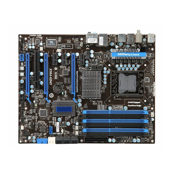
  • Seite 54: Komponenten-Übersicht

    M S-7522 M ainboard Komponenten-Übersicht CPUFAN1, De-18 JPWR2, De-13 CPU, De-5 DDR3, De-9 Back Panel, De-14 JPWR1, De-13 SYSFAN1/3, De-18 PCI_E, De-24 SATA, De-17 JSP1, De-22 SYSFAN2, IDE1, De-16 De-18 PCI, JTPM1, De-20 De-27 JFP2, JFP1, CPU_CLK1, De-19 De-28 JCOM1, De-19 CLR_CMOS1, JCI1, De-20 De-23...
  • Seite 55: Cpu (Central Processing Unit)

    Kühler, setzen Sie sich bitte mit Ihrem Händler in Verbindung, um einen solchen zu erwerben und zu installieren. Um die neuesten Informationen zu unterstützten Prozessoren zu erhalten, besuchen Sie bitte http://global.msi.com.tw/index.php?func=cpuform2 Wichtig Überhitzung Überhitzung beschädigt die CPU und das System nachhaltig. Stellen Sie stets eine k orrekte Funktionsweise des CPU Kühlers sicher, um die CPU vor...
  • Seite 56: Cpu & Kühler Einbau

    M S-7522 M ainboard CPU & Kühler Einbau Wenn Sie die CPU einbauen, stellen Sie bitte sicher, dass Sie auf der CPU einen Kühler anb r i ng en, um Ü ber hi t z un g z u ver mei den . Verg es s en S i e n i c h t , et was Siliziumwärmeleitpaste auf die CPU aufzutragen, bevor Sie den Prozessorkühler installieren, um eine Ableitung der Hitze zu erzielen.
  • Seite 57 5. Begutachten Sie, ob die CPU richtig 6. Schließen Sie die Abdeckung des im Sockel sitzt. Falls nicht, zeihen Sie Sockels. die CPU durch eine rein vertikale Bewegung wieder herau. Versuchen Sie es erneut. 7. Drücken Sie den Verschlusshebel mit 8.
  • Seite 58 M S-7522 M ainboard 9. Frühren Sie den CPU-Kühler über den 10. Drücken Sie die vier Stifte nach unten CPU-Sockel und positionieren Sie die um den Kühler zu arretieren. Arretierungsstifte des Kühlers über die dafür vorgesehenen Löcher des Mainboards. Drücken Sie den Kühler nach unten bis die Stif te in den Löchern eingerastet.
  • Seite 59: Speicher

    Speicher Diese DIMM-Steckplätze nehmen Arbeitsspeichermodule auf. Die neusten Informationen über kompatible Bauteile finden Sie unter http://global.msi. com.tw/index.php?func=testreport DDR3 240-polig, 1.5V 48x2=96 Pole 72x2=144 Pole Dual-Channel: Kanal A ist himmelblau; Kanal B ist rosa Hinweise für den Einsatz von Speichermodulen Bitte beachten Sie die folgenden Abbildungen zum Speichereinbau.
  • Seite 60 M S-7522 M ainboard Drei-Kanal Modus (Triple Channel) I m Dr ei -C hann el -M od us k ön nen Ar beit s s peic herm od ul e Daten üb er d rei Datenbusleitungen gleichzeitig senden und empfangen. Durch Aktivierung des Drei- Kanal-Modus wird die Leistung Ihres Systems nochmals verbessert.
  • Seite 61 Wichtig - DDR3 und DDR2 können nicht untereinander getauscht werden und der Stan- dard DDR3 ist nicht abwärtskompatibel. Installieren Sie DDR3 Speicher- module stets in DDR3 DIMM Slots. - Stellen Sie im Drei-/ Zweikanalbetrieb bitte sicher, dass Sie Module des gleichen Typs und identischer Speicherdichte in den DIMM Slots unterschiedlicher Kanäle verwenden.
  • Seite 62: Installieren Der Arbeitsspeichermodule

    M S-7522 M ainboard Installieren der Arbeitsspeichermodule 1. Das Arbeitsspeichermodul hat nur eine Kerbe in der Mitte und passt nur in eine Richtung in den Steckplatz. 2. Stecken Sie das Arbeitsspeichermodul senkrecht in den DIMM-Steckplatz ein. Drüc ken Sie ansc hließend das Arbeits speichermodul nach unten, bis die Kontaktseite richtig tief in dem DIMM-Steckplatz sitzt.
  • Seite 63: Stromversorgung

    Stromversorgung ATX 24-poliger Stromanschluss: JPWR1 Pole 13 Mit diesem Anschluss verbinden Sie den ATX 24-poligen Anschluss des Netzteils. Achten Sie bei dem Verbinden des ATX 24-poligen Stromanschlusses darauf, dass der Anschluss des Netzteils richtig auf den Anschluss an der Hauptplatine ausgerichtet ist. Drücken Sie dann den Anschluss des Netzteils fest nach unten, um eine richtige Verbindung zu gewährleisten.
  • Seite 64: Rücktafel

    M S-7522 M ainboard Rücktafel USB Ports 1394 Port Maus Line-In RS-Out Tastatur Line-Out CS-Out eSATA Port optische SS-Out USB Ports USB Ports S/PDIF- Ausgang M aus/Tastatur ® Die Standard PS/2 Maus/Tastatur Stecker Mini DIN ist für eine PS/2® Maus/Tastatur. Optische S/PDIF-Ausgang Dieser S/PDIF (Sony &...
  • Seite 65 Audioanschlüsse Diese Audioanschlüsse dienen zur Verbindung mit Audiogeräten. Durch die Farben erkennen Sie die unterschiedlichen Funktionen der Audioanschlüsse. Line-In (Blau) - Der Anschluss “Line In” kann einen externen CD-Player, , Tapeplayer oder ein sonstiges Audiogerät aufnehmen. Line-Out (Grün) - An den Anschluss “Line Out” können Sie Lautsprecher oder Kopfhörer anschließen.
  • Seite 66: Anschlüsse

    M S-7522 M ainboard Anschlüsse IDE Anschluss: IDE1 An diesem Anschluss können IDE Festplatten, optische Laufwerke und andere Geräte betrieben werden. Wichtig Verbinden Sie zwei Laufwerke über ein Kabel, müssen Sie das zweite Laufwerk im Slave-Modus konfigurieren, indem Sie entsprechend den Jumper setzen. Entnehmen Sie bitte die Anweisungen z um Setzen des Jumpers der Dokumentation der IDE Geräte, die der Festplattenhersteller zur Verfügung stellt.
  • Seite 67: Serial Ata Anschluss: Sata1

    Serial ATA Anschluss: SATA1~ 7 Der Anschluss ist eine Hochgeschwindigkeitsschnittstelle der Serial ATA. Pro Anschluss kann ein S-ATA Gerät angeschlossen werden. Die SATA1~6 Anschlüsse werden durch ICH10R unterstützt. SATA1_3 SATA2_4 SATA5_6 SATA7 wird durch SATA7 JMB363 kontrolliert Wichtig 1. Bitte falten Sie das Serial ATA Kabel nicht in einem Winkel von 90 Grad, da dies zu Datenverlusten während der Datenübertragung führt.
  • Seite 68 M S-7522 M ainboard Stromanschlüsse für Lüfter: CPUFAN1, SYSFAN1~3 Die Anschlüsse unterstützen aktive Systemlüfter mit + 12V. Wenn Sie den Anschluss herstellen, sollten Sie immer darauf achten, dass der rote Draht der positive Pol ist, und mit +12V verbunden werden sollte. Der schwarze Draht ist der Erdkontakt und sollte mit GND verbunden werden.
  • Seite 69: Frontpanel Anschluss: Jfp1, Jfp2

    Frontpanel Anschluss: JFP1, JFP2 Dieser Anschluss ist für das Frontpanel. Sie dienen zum Anschluss der Schalter und LEDs des Frontpanels. JFP1 erfüllt die Anforderungen des “Intel Front Panel I/O Connectivity Design Guide“. JFP1 Polzuweisung SIGNAL DESCRIPTION Power Power Switch HD_LED + Hard disk LED pull-up FP PWR/SLP MSG LED pull-up...
  • Seite 70: Tpm Modul Anschluss: Jtpm1

    M S-7522 M ainboard TPM Modul Anschluss: JTPM1 Dieser Anschluss wird für das optionale TPM Modul (Trusted Platform Module) verwendt. W eitere Informationen über den Einsatz des optionalen TPM Modules entnehmen Sie bitte dem TPM Plattform Handbuch. JTPM 1 Signal Description Signal Description...
  • Seite 71: Usb Vorderanschluss: Jusb1/ Jusb2

    USB Vorderanschluss: JUSB1/ JUSB2 ® Dieser Anschluss entspricht den Richtlinien des Intel I/O Connectivity Design Guide. Er ist bestens geeignet, Hochgeschwindigkeits- USB- Peripheriegeräte anzuschließen, wie z.B. USB Festplattenlaufwerke, Digitalkameras, M P3-Player, Drucker, M odems und ähnliches. Polzuweisung SIGNAL SIGNAL JUSB1/ JUSB2/ JUSB3 USB0- USB1- USB0+...
  • Seite 72 M S-7522 M ainboard Audioanschluss des Frontpanels: JAUD1 Dieser Anschluss ermöglicht den Anschluss von Audioein und -ausgängen eines Frontpanels. Der Anschluss entspricht den Richtlinien des “ Intel ® Front Panel I/O Connectivity Design Guide”. JAUD1 Polzuweisung für HD-Audio SIGNAL DESCRIPTION MIC_L Microphone - Left channel Ground...
  • Seite 73: Tasten

    Tasten Das Motherboard unterstützt die folgenden Tasten (optinoal), um die Funktion des Computers einzustellen. Dieser Abschnitt beschreibt, wie man die Funktionen des Motherboards durch den Gebrauch der Taste ändert. Ein-/Ausschalter: POWER1 Dieser Ein-/ Ausschalter verwendet, um das System ein- und auszuschalten. Drücken Sie diese Taste, um das System ein- bzw.
  • Seite 74: Steckplätze

    M S-7522 M ainboard Steckplätze PCI (Peripheral Component Interconnect) Express Steckplatz Der PCI Express-Steckplatz unterstützt eine Erweiterungskarte mit der PCI Express- Schnittstelle. Der PCI Express 2.0 x16-Steckplatz unterstützt eine Transferrate von bis zu 8.0 GB/ Der PCI Express 2.0 x4-Steckplatz unterstützt eine Transferrate von bis zu 2.0 GB/s. Der PCI Express 1.0 x1-Steckplatz unterstützt eine Transferrate von bis zu 250 MB/ PCI_E1 unterstützt bis zu die Geschwindigkeit PCI Express x1.
  • Seite 75 ATI CrossFireX (Multi-GPU) Technologie ATI CrossFireX ist die ultimative Multi-GPU Leistung Spielplattform. Wenn Spiel- beherrschender Energie ermöglicht, versetzt die ATI CrossFireX Technologie in die Lage zwei oder eigenstandige Graphikprozessoren zusammen zu arbeiten, um Sys- tem Leistung zu verbessern. Die ATI CrossFireX Technologie kann Graphikfähigkeiten Ihres Systems erweitern.
  • Seite 76 M S-7522 M ainboard 3.W enn alle Hardware und Software richtig aufgestellt worden ist und angebracht worden, neu starten Sie das System. Nachdem Sie das Betriebssystem eingetragen haben,, klicken Sie auf “Catalyst™ Control Center” Icon auf dem Desktop. Es gibt eine Einstellung in der Catalyst™ Control Center, die ermöglicht werden muss, damit CrossFire™...
  • Seite 77: Pci-Unterbrechungsanforderungs-Routing

    PCI (Peripheral Component Interconnect)-Steckplatz Der PCI-Steckplatz kann LAN-Karten, SCSI-Karten, USB-Karten und sonstige Zusatzkarten aufnehmen, die mit den PCI-Spezifikationen konform sind. 32-Bit PCI Steckplatz Wichtig Ac hten Sie darauf, dass Sie z uerst das Netz kabel aus der Stec kdose herausziehen, bevor Sie eine Erweiterungskarte installieren oder entfernen. Denken Sie bitte auch daran die Dokumentation der Erweiterungskarte zu lesen, um notwendige Hardware- oder Softwareeins tellungen fur die Erweiterungskarte wie z.B.
  • Seite 78: Schalter

    M S-7522 M ainboard Schalter Hardware Übertaktung FSB Steckbrücke: CPU_CLK1 Übertaken der FSB, um die Prozessorfrequenz erhöhen durch das Andern die Steckbrücke. Folgen Sie die Anleitungen zur Einstellung FSB. 1 2 3 1 2 3 1 2 3 133 MHz (default) 166 MHz 200 MHz Wichtig...
  • Seite 79: Led Statusdikatoren

    LED Statusdikatoren D I M M w a r n i n g L E D C P U P h a s e L E D s P C I E L E D P C I E L E D P C I E L E D P C I E L E D P C I E L E D...
  • Seite 80: Power-Led

    M S-7522 M ainboard DIMM Warning LED Leuchtet rot, wenn der Speicher falsch in DIMM_C0/ DIMM_C1 (die DIMMs des 3rd Kanal) eingebaut wurde. Power LED Leuchtet grün wenn das System eingeschaltet und betriebsbereit ist(S0/S1). Suspend LED Leuchtet gelb, wenn das System auf Bereitschaft (Stand-By) (S3/S4/ S5) ist. PCIE and PCI LEDs Leuchtet blau, wenn die Slots betriebsbereit ist.
  • Seite 81: Bios Setup

    BIOS Setup Dieses Kapitel enthält Informationen über das BIOS Setup und ermöglicht es Ihnen, Ihr System optimal auf Ihre Anforderungen einzustellen. Notwendigkeit zum Aufruf des BIOS besteht, wenn: * W ährend des Bootvorgangs des Systems eine Fehlermeldung erscheint und Sie zum Aufruf des BIOS SETUP aufgefordert werden.
  • Seite 82 M S-7522 M ainboard Aufruf des BIOS Setups Nach dem Einschalten beginnt der Computer den POST (Power On Self Test - Selbstüberprüfung nach Anschalten). Sobald die Meldung unten erscheint, drücken Sie die Taste <Entf>(<Del>) um das Setup aufzurufen. Press DEL to enter SETUP Wenn die Nachricht verschwindet, bevor Sie reagieren und Sie möchten immer noch ins Setup, starten Sie das System neu, indem Sie es erst AUS- und danach wieder ANSCHALTEN, oder die “RESET”-Taste am Gehäuse betätigen.
  • Seite 83 Das Hauptmenü ® ® Nachdem Sie das AMI oder AWARD BIOS CMOS Setup Utility, aufgerufen haben, erscheint das Hauptmenü. Es weist die Setup- Funktionen und zwei Arten das Menü zu verlassen auf. Verwenden Sie die Pfeiltasten, um im Menü zu navigieren und drücken Sie die Eingabetaste (<Enter>), um ein Untermenü...
  • Seite 84 Drücken Sie auf [OK] und <Enter>, um die (neuen) Einstellungen zu speichern und das BIOS Setup zu verlassen. Wichtig Die Konfiguration oben dienen nur generellen Zwecken. Wenn Sie detaillierte BIOS- Einstellungen benötigen, dann s ehen Sie bitte das Handbuch in Englischer Sprache auf der MSI Website ein. De-34...
  • Seite 85 4. Cell M enu Introduction : Das Menü ist für den weiteren Benutzer, der die Hauptplatine übertakten mögen. Wichtig Nur wenn Sie mit dem Chipsatz vertraut sind, können Sie die Einstellung ändern . Current Core / DRAM / QPI Frequency Zeigt die derzeitige Frequenz der CPU/ Speicher.
  • Seite 86 M S-7522 M ainboard CPU Specifications Drücken Sie die Eingabetaste <Enter>, um das folgende Untermenü aufzurufen. Das Untermenü zeigt die Informationen angebrachter CPU an. CPU Technology Support Drücken Sie die Eingabetaste <Enter>, um das folgende Untermenü aufzurufen. Das Untermenü zeigt die Technologien an, die die angebrachte CPU stützt. Intel EIST Die erhöhte Intel SpeedStep Technologie erlaubt Ihnen, das Leistungsgrad des Mikroprozessors einzustellen, ob der Computer auf Batterie oder Wechselstrom läuft.
  • Seite 87 Intel Turbo Boost tech Das Untermenü erscheint, wenn Sie eine CPU anbringen, die die Intel Turbo Boost Technologie aufnehmt. Und hier können Sie die Intel Turbo Boost Technologie aktiviert/ deaktiviert. Für weitere Informationen beziehen Sie in offizielle Website des Intel. Adjusted Core Frequency (M Hz) Gibt der verstellt Frequenz des CPU (Grundtakt x Ratio).
  • Seite 88 M S-7522 M ainboard Advance DRAM Configuration Drücken Sie die Eingabetaste <Enter>, um das folgende Untermenü aufzurufen. 1N/2N M emory Timing Können Sie hier die DRAM Timing angeben. Legt die SDRAM Kommandorate fest. Die Einstellung 1N lässt den SDRAM Signal Kontroller mit einem 1N ((Taktzyklus) laufen.
  • Seite 89 ClockGen Tuner Drücken Sie die Eingabetaste <Enter>, um das folgende Untermenü aufzurufen. CPU / PCI Express Amplitude Control Gestattet die Wahl der CPU-Takt oder PCI-E Takt. CPU CLK Skew/ IOH CLK Skew Gestattet die Wahl der CPU/ North-Bridge Chipsatztakt,durch Einstellung eines höheren CPU Taktes.
  • Seite 90 M S-7522 M ainboard Spread Spectrum Pulsiert der Taktgenerator des Motherboards, erzeugen die Extremwerte (Spitzen) der Pulse EMI (Elektromagnetische Interferenzen). Die Spread Spectrum Funktion reduziert die erzeugten EMI, indem die Pulse so moduliert werden, das die Pulsspitzen zu flacheren Kurven reduziert werden. Wichtig 1.
  • Seite 91: Software-Information

    Gebrauchsmenü - das Gebrauchsmenü zeigt die Software-Anwendungen der die Mainboard Unterstützungen. WebSite Menü - das Website Menü zeigt die betreffende Website. Wichtig Besuchen Sie bitte die MSI Website, um die neuesten Treiber und BIOS für bessere System Leistung zu erhalten. De-41...
  • Seite 92: Français

    X58 Pro Séries Guide d’utilisation Français Fr-1...
  • Seite 93 Carte mère M S-7522 Spécifications Processeurs supportés ® - Intel i7 processeurs dans le paquet LGA1366 (Pour plus d’informations sur le CPU, veuillez visiter http://global.m si.com.tw/index.php?func=cpuform 2) QPI supporté - Jusqu’à 6.4 GT/s Chipset ® - North Bridge : Chipset Intel ®...
  • Seite 94 Connecteurs Panneau arrière - 1 port souris PS/2 - 1 port clavier PS/2 - 1 port optique S/PDIF-Out - 1 port 1394 - 1 port eSATA - 6 ports USB 2.0 - 1 jack LAN - 6 jacks audio flexbiles Connecteurs intégrés - 3 connecteurs USB 2.0 - 1 connecteur 1394...
  • Seite 95: Guide Rapide Des Composants

    Carte mère M S-7522 Guide rapide des composants CPUFAN1, Fr-18 JPWR2, Fr-13 CPU, Fr-5 DDR3, Fr-9 Panneau arrière, Fr-14 JPWR1, Fr-13 SYSFAN1/3, Fr-18 PCI_E, Fr-24 SATA, Fr-17 JSP1, Fr-22 SYSFAN2, Fr-18 IDE1, Fr-16 PCI, JTPM1, Fr-20 Fr-27 JFP2, JFP1, CPU_CLK1, Fr-19 Fr-28 JCOM1, Fr-19...
  • Seite 96: Processeur : Cpu

    équipée d’un ventilateur de refroidissement attaché sur le dessus pour éviter la surchauffe. Si vous n’en avez pas, contactez votre revendeur pour en acheter et installez les avant d’allumer votre ordinateur. Pour plus d’informations sur le CPU, veuillez visiter http://global.msi.com.tw/index. php?func=cpuform2 Important Surchauffe La surchauffe endommage sérieusement l’unité...
  • Seite 97: Installation Du Cpu Et Son Ventilateur

    Carte mère M S-7522 Installation du CPU et son ventilateur Quand vous installez le CPU, veuillez vous assurer que l’unité centrale soit équipée d’un ventilateur de refroidissement attaché sur le dessus pour éviter la surchauffe. Méanmoins, n’oubliez pas d’appliquer une couche d’enduit thermique sur le CPU avant d’installer le ventilateur pour une meilleure dissipation de chaleur.
  • Seite 98 5. Inspectez visuellement si le CPU est 6. Couvrez le plat de c harge sur le bien posé dans le douille. Sinon, paquet. sortez verticalement le CPU pur et la réinstallez. 8. Inspectez si les quatre crochets sont 7. Abaissez le levier sur le plateau de c h a r g e m e n t , p u i s s é...
  • Seite 99 Carte mère M S-7522 9. Alignez les trous de la carte avec le 10. Appuyez sur les quatre crochets dissipateur thermique. Appuyez sur afin de fixer le ventilateur. le ventilateur jusqu’à ce que les clips soient coincés dans les trous de la carte mère.
  • Seite 100: Mémoire

    Mémoire Ces slots de DIMM sont destinés à installer les modules de mémoire. Pour plus d’informations sur les composants compatibles, veuillez visiter http://global. msi.com.tw/index.php?func=testreport DDR3 240-pin, 1.5V 48x2=96 pin 72x2=144 pin Double-canaux : Canal A est en BLEU CIEL ; Canal B est en ROSE Règles de population de la mémoire...
  • Seite 101 Carte mère M S-7522 M ode trois-canaux En mode trois-canaux, les modules de mémoire peuvent transmettre et recevoir les données avec trois lignes bus de données sémultanément. L’activation du mode trois-canaux peut l’augmenter à la meuilleure performance du système. Quand vous avez trois ou plus de modules de mémoire, veuillez toujours les insérer comme les façons 3/ 4/ 5/ 6 (montré...
  • Seite 102 Important - Les modules de mémoire DDR3 ne sont pas interchangeables par DDR2 et vice versa. Vous devez toujours installer les modules de mémoire DDR3 dans les slots DDR3 DIMM. - En mode trois-/ double- canaux, assurez-vous que vous installez les mod- ules de mémoire du même type et de la même densité...
  • Seite 103 Carte mère M S-7522 Installation des modules de mémoire 1. Le module de mémoire possède une seule encoche en son centre et ne s’adaptera que s’il est orienté de la manière convenable. 2. Insérez le module de mémoire à la verticale dans le slot du DIMM. Poussez-le ensuite jusqu’à...
  • Seite 104: Connecteur D'alimentation

    Connecteurs d’alimentation Connecteur d’alimentation ATX 24-Pin : JPWR1 pin 13 Ce connecteur vous permet de connecter l’alimentation ATX 24-pin. Pour cela, assurez-vous que la pris e d’alimentation est bien positionnée dans le bon sens et que les goupilles soient alignées. Enfoncez alors la prise dans le connecteur.
  • Seite 105: Panneau Arrière

    Carte mère M S-7522 Panneau arrière Ports USB Port 1394 Souris Ligne-In RS-Out Clavier Ligne-Out CS-Out Port Optique Port eSATA Ports USB Ports USB SS-Out S/PDIF-Out Souris/Clavier ® Le standard connecteur de souris/clavier DIN de PS/2 est pour une souris ou un ®...
  • Seite 106 Ports Audio Ces connecteurs audio servent pour les périphériques audio. Vous pouvez différencier la couleur des prises audio pour obtenir divers effets sonores. Ligne-In (Bleu) - Ligne In, est utilisée pour un appareil de CD externe, cassette ou d’autre périphériques. Ligne-Out (Vert) - Ligne Out, est destiné...
  • Seite 107: Connecteurs

    Carte mère M S-7522 Connecteurs Connecteur IDE : IDE1 Ce connecteur supporte les lecteurs de disque dur IDE, lecteurs optiques de disque et d’autre périphériques IDE. Important Si vous installez deux périphériques IDE sur le même câble, vous devez configurer les périphériques séparément en mode Master/ Slave par les c av a liers d e c onfiguratio n.
  • Seite 108 Connecteur Sérial ATA : SATA1~ 7 Ce connecteur est un port d’interface de sérial ATA haut débit. Chaque connecteur peut être relié à un appareil de sérial ATA. Connecteurs SATA1~6 stack SATA sont supportés par ICH10R SATA1_3 SATA2_4 SATA5_6 SATA7 est supporté par SATA7 JM B363 Important...
  • Seite 109 Carte mère M S-7522 Connecteur d’alimentation du ventilateur : CPUFAN1, SYSFAN1~3 Les connecteurs de courant du ventilateur supportent le ventilateur de refroidissement du système avec +12V. Lors du branchement des fils aux connecteurs, faites toujours en sorte que le fil rouge soit le fil positif devant être relié au connecteur +12V; et que le fil noir soit le fil de mise à...
  • Seite 110 Connecteurs du panneau avant : JFP1, JFP2 Ces connecteurs sont fournis pour la connecxion électrique aux interrupteuts et LEDs du panneau avant. Le JFP1 est c onforme au guide de conc eption de la ® connectivité Entrée/sortie du panneau avant Intel Définition des pins pour JFP1 SIGNAL DESCRIPTION...
  • Seite 111 Carte mère M S-7522 Connecteur du Module TPM : JTPM1 Ce connecteur est rélié à TPM (Trusted Platform Module) Module (optionnel). Veuillez vous référer au manuel de TPM plat-forme de sécurité pour plus de détails et d’utilisations. JTPM 1 Signal Description Signal Description...
  • Seite 112 Connecteur USB avant : JUSB1/ JUSB2/ JUSB3 Ce connecteur est conforme au guide de conception de la connectivité Entrée/sortie , il est idéal pour relier les périphériques d’interface USB à ® du panneau avant Intel haut débit tels les disques durs externes, les appareils photo numériques, les lecteurs M P3, les imprimantes, les modems et les appareils similaires.
  • Seite 113 Carte mère M S-7522 Connecteur audio panneau avant : JAUD1 Ce connecteur vous permet de connecter un audio sur le panneau avant. Il est conforme au guide de conception de la connectivité Entrée/sortie du panneau avant ® Intel JAUD1 Définition de pins pour HD Audio SIGNAL DESCRIPTION MIC_L...
  • Seite 114: Boutons

    Boutons Cette carte mère vous fournit les boutons suivants (optinnel) pour régler les fonctions de l’ordinateur. Cette partie vous explique comment changer les fonctions de votre carte mère par ces boutons. Bouton d’alimentation : POWER1 Ce bouton d’alimentation sert à allumer ou éteindre le système. Appuyez sur ce bouton pour allumer ou éteindre le système.
  • Seite 115: Slots

    Carte mère M S-7522 Slots Slot PCI (Peripheral Component Interconnect) Express Le slot PCI Express supporte la carte d’expension de l’interface du PCI Express. Le slot PCI Express 2.0 x4 supporte un taux de transfert jusqu’à 2.0 GB/s. Le slot PCI Express 1.0 x1 supporte un taux de transfert jusqu’à 250 MB/s. PCI_E1 supporte la vitesse jusqu’à...
  • Seite 116 Technologie ATI CrossFireX (Multi-GPU) ATI CrossFireX est le plate-forme de jeux de la performance ultimate Multi-GPU. L’alimentation game-dominating activée, la technologie ATI CrossFireX active deux ou plus de processeurs graphiques discrets pour qu’ils fonctionnent ensemble pour améliorer la performance de votre système. La technologie ATI CrossFireX vous permet d’élargir les capacités de votre système graphic.
  • Seite 117 Carte mère M S-7522 3. Quand le matériel et le logiciel sont tous correctement installés, réinitialisez le système. Après entrer dans le O.S., cliquez sur l’icône de “Catalyst™ Control Center” sur le bureau. Il y a un réglage dans le Catalyst™ Control Center qui doit être activé...
  • Seite 118 Slot PCI (Peripheral Component Interconnect) Le slot PCI supporte la carte LAN, la carte SCSI, la carte USB et d’autres cartes ajoutées qui sont compatibles avec les spécifications de PCI. Slot 32-bit PCI Important Lorsque vous ajoutez ou retirez une carte d’extension, assurez-vous que le PC n’est pas relié...
  • Seite 119: Interrupteur

    Carte mère M S-7522 Interrupteur Interrupteur d’horloge du base d’overclocking du Matériel : CPU_CLK1 Vous pouvez overclocker l’horloge du base pour augmenter la fréquenc e du processeur en changeant cet interrupteur. Suivez les instructions suivantes pour régler l’horloge du CPU. 1 2 3 1 2 3 1 2 3...
  • Seite 120: Indicateurs Du Statut Led

    Indicateurs du statut LED D I M M w a r n i n g L E D C P U P h a s e L E D s P C I E L E D P C I E L E D P C I E L E D P C I E L E D P C I E L E D...
  • Seite 121 Carte mère M S-7522 LED d’Alarme DIMM Il s’allume rouge lorsque une fausse mémoire est installée dans le DIMM_C0/ DIMM_C1 (Le DIMMs pour le 3eme canal). LED d’alimentation Il s’allume vert lorsque le système est au statut power-on(S0/S1). LED Attente Il s’allume jaune lorsque le système est au mode attente.
  • Seite 122: Réglages Bios

    Réglages BIOS Ce chapitre donne des informations concernant le programme de réglage de BIOS et vous permet de configurer le système pour obtenir des performances d’utilisation optimum. Vous aurez peut-être besoin de lancer le programme de réglage quand : * Un message d’erreur apparaît sur l’écran pendant le démarrage du système, qui vous demande de lancer SETUP (Réglage).
  • Seite 123 Carte mère M S-7522 Réglages d’Entrée Allumez l'ordinateur et le système lancera le processus POST (Test automatique d'allumage). Lorsque le message ci-dessous apparaît à l'écran, appuyez sur la tou- che <DEL> pour entrer dans les réglages. Appuyez sur DEL pour entrer dans SETUP Si le message disparaît avant que vous ne répondiez et que vous souhaitez encore entrer dans Setup (Réglages), redémarrez le système en OFF (éteignant) puis en On (rallumant) en appuyant sur le bouton RESET (Réinitialiser).
  • Seite 124 M enu principal ® ® Une fois entré dans l’unité de réglages AMI ou AWARD BIOS CMOS, le Menu princi- pal appaît sur l’écran. Le Menu Principal vous permet de sélectionner de dix foncions de réglage et deux choix de sortie. Utilisez les touches de flèche pour sélectionner parmi les objets et appuyez sur <Enter>...
  • Seite 125 Choisir [Ok] et appuyer sur Enter afin de sauvegarder les configurations et l’unité de réglages de quitter BIOS. Important Les configurations précédantes ne sont que pour l’utilisation générale. Si vous avez besoin de réglages détaillés du BIOS, veuillez vous référer au manuel de l’édition anglaise sur la page d’internet de MSI. Fr-34...
  • Seite 126 4. Cell Menu Introduction (Introduction du Menu cell) : Ce menu est pour des utilisations avancée destinée à overclocker la carte mère. Important Ne changez pas ces réglages sauf que vous connaissiez bien ces chipsets. Current Core / DRAM / QPI Frequency Ces articles montrent les horloges actuelles de la vitesse du CPU et de la mémoire.
  • Seite 127 Carte mère M S-7522 CPU Spécifications Appuyez sur <Enter> pour entrer dans le sous-menu et il apparaîtra l’écran suivant. Ce sous-menu montre des informations du CPU installé. CPU Technology Support Appuyez sur <Enter> pour entrer dans le sous-menu et il apparaîtra l’écran suivant.
  • Seite 128 Intel Turbo Boost tech Cet article apparaîtra quand vous installez un CPU avec la technologie Intel Turbo Boost. Cet article sert à activer/ désactiver la technologie Intel Turbo Boost. Pour plus d’informations veuillez vous référer au site officiel d’Intel's. Adjusted Core Frequency (M Hz) Il montre la fréquence ajustée du CPU (Horloge du Base x Ratio).
  • Seite 129 Carte mère M S-7522 Advance DRAM Configuration Appuyez sur <Enter> pour entrer dans le sous-menu et il apparaîtra l’écran suivant. 1N/2N M emory Timing Cet article contrôle le taux d’ordre du SDRAM. La sélection en [1N] fait fonctionner en taux de 1N (N=cycles d’horloge) au contrôleur du signaux du SDRAM. La sélection en [2N] fait fonctionner en taux de 2N au contrôleur du signaux du SDRAM.
  • Seite 130 Adjusted DRAM Frequency (MHz) Il montre la fréquence de la mémoire DDR ajustée. Lecture uniquement. ClockGen Tuner Appuyez sur <Enter> pour entrer dans le sous-menu et il apparaîtra l’écran suivant. CPU / PCI Express Amplitude Control Ces articles servent à sélectionner l’amplitude d’horloge du CPU/ PCI Express. CPU CLK Skew/ IOH CLK Skew Ces articles servent à...
  • Seite 131 Carte mère M S-7522 Spread Spectrum Lorsque le clock generator de la carte mère fonctionne, les valeurs extrêmes (spikes) créent des interférences électromagnétiques (EMI-Electromagnetic Interference). La fonction Spread Spectrum réduit ces interférences en réglant les impultions. Si vous n’avez pas de problème d’EMI ceci vous permet d’avoir une stabilité du système et des performances optimales.
  • Seite 132: Information De Logiciel

    Menu de services – Il montre les applications logicielles supportées par la carte mère. Menu du site Web – Il vous indique les sites webs utiles. Important Veuillez consulter le site Web de MSI pour obtenir les derniers pilotes et BIOS pour améliorer l’exécution du système de votre ordinateur. Fr-41...
  • Seite 133: Руководство Пользователя

    Серия X58 Pro Руководство пользователя Русский Ru-1...
  • Seite 134: Характеристики

    MS-7522 Системная плата Характеристики Процессоры - Процессоры Intel i7 в конструктиве LGA1366 ® (Для получения самой новой информации о CPU, посетите сайт http://global.m si.com.tw/index.php?func=cpuform 2) - Скорость до 6.4 ГТ/с Чипсет - Северный мост: Intel ® - Южный мост: Intel ®...
  • Seite 135 Коннекторы Задней панели - 1 PS/2 порт мыши - 1 PS/2 порт клавиатуры - 1 разъем Optical S/PDIF-Out - 1 порт 1394 - 1 порт eSATA - 6 портов USB 2.0 - 1 разъем LAN - 6 звуковых разъемов с гибким переназначением Разъемы, установленные...
  • Seite 136: Руководство По Размещению Компонентов

    MS-7522 Системная плата Руководство по размещению компонентов CPUFAN1, Ru-18 JPWR2, Ru-13 CPU, Ru-5 DDR3, Ru-9 Back Panel, Ru-14 JPWR1, Ru-13 SYSFAN1/3, Ru-18 PCI_E, Ru-24 SATA, Ru-17 JSP1, Ru-22 SYSFAN2, IDE1, Ru-16 Ru-18 PCI, JTPM1, Ru-20 Ru-27 JFP2, JFP1, CPU_CLK1, Ru-19 Ru-28 JCOM1, Ru-19 CLR_CMOS1,...
  • Seite 137: Cpu (Центральный Процессор)

    кулера, пожалуйс та, свяжитес ь с дилером с цель ю приобретения и его установки до того, как включите компьютер. Самую последнюю информацию о CPU можно получить на сайте http://global. msi.com.tw/index.php?func=cpuform2 Внимание Перегрев Перегрев может серьезно повредить центральный процессор и систему.
  • Seite 138 MS-7522 Системная плата Установка процессора и вентилятора Во избежание перегрева при работе обязательно установите вентилятор процессора. Одновременно, чтобы увеличить теплорассеивание, убедитесь в том, что нанесен слой теплопроводящей пасты на процессоре при установке вентилятора. Следуйте данным указаниям для правильной установки. Неправильная установка приведет...
  • Seite 139 5. В и з у а л ь н о п р о в е р ь т е 6. Опустите маталлическую крышку п р а в и л ь н о с т ь у с т а н о в к и механизма...
  • Seite 140 MS-7522 Системная плата 9. Совместите отверстия системной 10 .Нажмите на четыре защелки и платы с защелками крепления закрепите вентилятор. вентилятора. Прижмите радиатор с венти лятором к процес с ору и проследите, чтобы четыре защелки вошли в отверстия системной платы. 11. Переверните системную плату и 12.
  • Seite 141: Память

    Память Слоты DIMM используются для установки модулей памяти. За дополнительной информацией о совместимых компонентах посетите сайт http://global.msi.com.tw/index.php?func=testreport DDR3 240-конт, 1.5V 48x2=96 конт 72x2=144 конт Два канала: Канал A в Голубым цветом; канал B в Розовым Правила установки модулей памяти Ниже приведены правила заполнения слотов памяти.
  • Seite 142 MS-7522 Системная плата Трёхканальный режим В трёхканальном режиме модули памяти могут передавать и принимать данные по 3 шинам одновременно. При использовании трёхканального режима обеспечивается максимальная производительность системы. Если у вас три или больше модулей памяти, то установите их как показано на рис. 3/ 4/ 5/ 6 для...
  • Seite 143 Внимание - Модули DDR3 не взаимозаменяемы с модулями DDR2 и стандарт DDR3 не имеет обратной совместимости. Следует устанавливать модули памяти DDR3 в разъемы DDR3. - Для работы в трёхканальном/ двухканальном режиме убедитесь, что в разъемах разных каналов у вас установлены модули одного типа и одинаковой...
  • Seite 144 MS-7522 Системная плата Установка модулей памяти 1. Модули памяти имеют только одну прорезь в середине. Модуль войдет в разьем только при правильной ориентации. 2. Вставьте модуль в DIMM слот в вертикальном направлении. Затем нажмите на него, чтобы золоченые контакты глубоко погрузились в DIMM слот. Если модуль...
  • Seite 145: Разъем Питания

    Разъем питания 24-контактный разъем питания ATX: JPWR1 pin 13 Этот разъем позволяет подключить 24-контактный коннектор питания ATX. Для подключения источника убедитесь, что его разъем и контакты правильно сориентированы. Затем плотно вставьте его в разъем на системной плате. Вы также можете использовать блок питания с 20-контактным разъемом.
  • Seite 146: Задняя Панель

    MS-7522 Системная плата Задняя панель Разъем LAN Порты Порт 1394 Мышь Линейный RS-выход вход Клавиатура Линейный CS-выход выход Микрофон SS-выход Порт eSATA Порт Optical Порты USB Порты USB S/PDIF-Out Порт мыши/клавиатуры Стандартные разъемы DIN PS/2 для подключения мыши/клавиатуры с ® интерфейсом...
  • Seite 147 Цвет Состояние LED Описание Нет LAN соединение не установлено. Лев. Жёлт . Есть (постоянно) LAN соединение установлено. Есть (ярче & мигает) Связъ с другим компьютером по LAN. Зелен. Нет Скорость передачи 10 Мб/с. Прав. Есть Скорость передачи 100 Мб/с. Оранж. Есть...
  • Seite 148: Коннекторы

    MS-7522 Системная плата Коннекторы Разъем IDE: IDE1 Разъем поддерживает жёсткий диск IDE, дополнительное дисковое устройство и другие устройства с интерфейсом IDE. Внимание При подключении двух устройств на одном кабеле, следует установить устройства в режим master / slave посредством установки перемычки. За...
  • Seite 149 Разъем Serial ATA: SATA1~ 7 Данный разъем является высокоскоростным портом интерфейса Serial ATA. Любой разъем Serial ATA может соединяться с одним устройством Serial ATA. Разъемы SATA1~6 работают на чипсете ICH10R SATA1_3 SATA2_4 SATA5_6 SATA7 работает на SATA7 чипсете JM B363 Внимание...
  • Seite 150 MS-7522 Системная плата Разъемы питания вентиляторов: CPUFAN1, SYSFAN1~3 Разъемы питания вентиляторов поддерживают вентиляторы с питанием +12В. При подключении необходимо помнить, что красный провод подключается к шине +12В, черный - к земле GND. Если на системной плате установлена микросхема аппаратного мониторинга, необходимо использовать специальные вентиляторы с...
  • Seite 151 Коннекторы передней панели: JFP1, JFP2 Эти коннекторы ис поль зуются для подключения кнопок и индикаторов, расположенных на передней панели корпуса. Коннектор JFP1 соответствует руководству Intel ® Front Panel I/O Connectivity Design. JFP1 Pin Definition SIGNAL DESCRIPTION Power Power Switch HD_LED + Hard disk LED pull-up FP PWR/SLP MSG LED pull-up...
  • Seite 152 MS-7522 Системная плата Разъем TPM Модуля: JTPM1 Данный разъем подключаетс я к модулю TPM (T rus ted Platf orm Module) (опционально). За более подробной информацией и назначениями обращайтесь к описанию модуля TPM. JTPM 1 Signal Description Signal Description LCLK LPC clock 3V_STB 3V standby power LRST#...
  • Seite 153: Разъем Cd-In: Jcd1

    Разъем USB передней панели: JUSB1/ JUSB2/ JUSB3 Разъем, соответствует спецификации Intel I/O Connectivity Design, идеально ® подходит для подключения таких высокоскоростных периферийных устройств, как USB HDD, цифровые камеры, MP3 плееры, принтеры, модемы и им подобные. Pin Definition SIGNAL SIGNAL JUSB1/ JUSB2/ JUSB3 USB0- USB1- USB0+...
  • Seite 154 MS-7522 Системная плата Выносной разъем аудио: JAUD1 Этот коннектор позволяет подключить выносной разъем аудио на передней панели и соответствует руководству Intel ® Front Panel I/O Connectivity Design Guide. JAUD1 HD Audio Pin Definition SIGNAL DESCRIPTION MIC_L Microphone - Left channel Ground MIC_R Microphone - Right channel...
  • Seite 155: Кнопки

    Кнопки На этой с истемной плате имеются дополнительные кнопки для установки функций компьютера. Эта глава поясняет возможности использования каждой из кнопок. Кнопка питания: POWER1 Эта кнопка используется для включения и выключения системы. Нажмите эту кнопку, чтобы включить или выключить сис тему. Кнопка горит при включении...
  • Seite 156: Слоты

    MS-7522 Системная плата Слоты Слот PCI (Peripheral Component Interconnect) Express Слот PCI Express поддерживает карты расширения интерфейса PCI Express. PCI Express 2.0 x16 поддерживает скорость передачи данных до 8.0 ГБ/с. PCI Express 2.0 x4 поддерживает скорость передачи данных до 2.0 ГБ/с. PCI Express 1.0 x1 поддерживает...
  • Seite 157 Технология ATI CrossFireX (Multi-GPU) Технология ATI CrossFireX (Multi-GPU) позволяет нескольким графическим картам работать вместе. Для использования CrossFireX с видеокартами более ранних поколений требуетс я одна карта Cros s FireX Edition и еще одна совместимой модели (CrossFireX Ready) из той же серии. Для таких видеокарт всегда...
  • Seite 158 MS-7522 Системная плата 3 .П ос л е ус т ан овк и в с его ап п ар ат н ог о и п р ог рам мн ог о обес печ ен ия , перезагрузите систему. После входа в операционную систему, кликните значок “Catalyst™...
  • Seite 159 Слот PCI (Peripheral Component Interconnect) Слот PCI позволяет установить карты LAN, SCSI, USB и другие дополнительные карты расширения, которые соответствуют характеристикам PCI. 32-bit PCI слот Внимание Перед установкой или извлечением карт расширения убедитесь, что к аб ел ь питания отк л ючен от эл ек тричес к ой с ети. Прочтите док...
  • Seite 160: Переключатели

    MS-7522 Системная плата Переключатели Переключатели аппаратного разгона тактовой частоты: CPU_CLK1 Перестановка этих переключателей позволяют увеличивать тактовую частоту сис темы, таким образом повышая частоту процес сора. Следуйте данным указаниям для установки тактовой частоты. 1 2 3 1 2 3 1 2 3 1 3 3 MH z ( п...
  • Seite 161: Световые Индикаторы

    Световые индикаторы D I M M w a r n i n g L E D C P U P h a s e L E D s P C I E L E D P C I E L E D P C I E L E D P C I E L E D P C I E L E D...
  • Seite 162 MS-7522 Системная плата DIMM Warning LED Горит красным, когда установлена несовместимая память в DIMM_C0/ DIMM_C1 (слоты DIMM 3-ого канала) Power LED Горит зелёным, когда система включена (S0/S1). Suspend LED Горит желтым при спящем режиме системы (S3/S4/S5 ). PCIE and PCI LEDs Горит...
  • Seite 163: Настройка Bios

    Настройка BIOS В этой главе приводятся основные сведения о режиме настройки BIOS (BIOS SETUP), который позволяет установить оптимальную конфигурацию системы. Этот режим может потребоваться в следующих случаях: * Во время загрузки системы появляется сообщение об ошибке с требованием запустить BIOS SETUP. * Вы...
  • Seite 164: Режим Настройки

    MS-7522 Системная плата Вход в режим настройки Включите питание компьютера. При этом запустится процедура POST (Тест включения питания). Когда на экране появится приведенное ниже сообщение, нажмите клавишу <DEL> для входа в режим настройки. Press DEL to enter SETUP Если сообщение исчезло, а вы не ус пели нажать клавишу, перезапустите систему, выключив...
  • Seite 165 The M ain M enu (Главное меню) При входе в режим настройки BIOS от AMI ® или AWARD ® на экране отображается Главное меню. Главное меню позволяет выбрать десять функций настройки и имеет два варианта выхода. Для перемещения по пунктам используются клавиши...
  • Seite 166 Setup и нажмите <Enter>, появится следующее сообщение: Нажмите [Ok], чтобы сохранить конфигурацию и выйти из BIOS Setup. Внимание Приведенная выше конфигурация подходит для общего применения. Если же вам требуются более тонкие настройки BIOS, обратитесь к английской версии руководства на веб-сайте MSI. Ru-34...
  • Seite 167 4. Cell M enu Introduction : Это меню позволяет управлять тактовыми частотами при разгоне. Внимание Не меняйте эти настройки, если вы не знакомы с данным чипсетом. Current Core / DRAM / QPI Frequency Эти пункты показывают текущую частоту CPU и скорость памяти. Только для чтения.
  • Seite 168 MS-7522 Системная плата CPU Specifications Нажмите <Enter> для входа в подменю и появляется нижеследующий экран. В подменю показана информация об установленном CPU. CPU Technology Support Нажмите <Enter> для входа в подменю и появляется нижеследующий экран. В подменю показаны технологии, поддерживаемые установленным CPU. Intel EIST Техн...
  • Seite 169 Intel Turbo Boost tech Этот п укнт появл яетс я, ког да вы ус тан овили CPU , поддержи вающий технологию Intel T urbo Boos t. Этот пункт ис поль зуетс я для включения/ выключения технологии Intel Turbo Boost. За дополнительной информацией обратитесь...
  • Seite 170 MS-7522 Системная плата Advance DRAM Configuration Нажмите <Enter> для входа в подменю и появляется нижеследующий экран. 1N/2N M emory Timing Этот пункт определяет скорость выдачи команд SDRAM. Выбор [1N] переводит сигнальный котроллер SDRAM в режим работы1N (N=clock cycles). Выбор [2N] переводит сигнальный котроллер SDRAM в режим работы...
  • Seite 171 ClockGen Tuner Нажмите <Enter> для входа в подменю и появляется нижеследующий экран. CPU / PCI Express Amplitude Control Эти пункты используются для выбора амплитуды тактового сигнала CPU/ PCI Express. CPU CLK Skew/ IOH CLK Skew Эти пункты используются для выбора фазового сдвига тактового сигнала для...
  • Seite 172 MS-7522 Системная плата Spread Spectrum Так как тактовый генератор сис темной платы импульс ный, то его работа вызывает электромагнитные помехи - EMI (Electromagnetic Interference). Функция Spread Spectrum снижает эти помехи, генерируя сглаженные импульсы. Если у вас нет проблем с помехами, оставьте значение [Disabled] (запрещено) для лучшей...
  • Seite 173: Сведения О Программном Обеспечении

    для активации устройства. Utility menu (Меню утилит) - Содержит прикладные программы для поддержки системной платы. Service base menu - Содержит список необходимых вебсайтов. Внимание Пожалуйста, посетите вебс айт MSI для получения самых новых драйверов и BIOS, которые позволят улучшить производительность системы. Ru-41...

Diese Anleitung auch für:

Ms-7522

Inhaltsverzeichnis