Inhaltsverzeichnis
Werbung
Verfügbare Sprachen
Verfügbare Sprachen
Montage- und Betriebsanleitung
DE
Einzelraumlüftungsgerät PushPull mit
Wärmerückgewinnung
Mounting and operating instructions
EN
PushPull single-room ventilation unit with
heat recovery
Instructions de montage et mode d'emploi
FR
Appareil de ventilation pour pièce individuelle PushPull
à récupération de chaleur
w w w . m a i c o - v e n t i l a t o r e n . c o m
PP 60 KA
PP 60 KL
Werbung
Kapitel
Inhaltsverzeichnis

Verwandte Anleitungen für Maico PP 60 KA


Inhaltszusammenfassung für Maico PP 60 KA
- Seite 1 Instructions de montage et mode d'emploi Appareil de ventilation pour pièce individuelle PushPull à récupération de chaleur PP 60 KA PP 60 KL w w w . m a i c o - v e n t i l a t o r e n . c o m...
- Seite 2 Montage- und Mounting and operating Instructions de montage Betriebsanleitung instructions et mode d'emploi Seite 2 Page 22 Page 41 Lesen Sie diese Montage- You should read these Prière de lire attentivement und Betriebsanleitung mounting and operating et entièrement les présentes aufmerksam durch, bevor instructions carefully before instructions de montage et le...
-
Seite 4: Inhaltsverzeichnis
| Geräteübersicht, Abb. A, B, C, D Geräteübersicht, Abb. A, B, C, D Inhaltsverzeichnis Abb. A, PP 60 KA-SR und PP 60 K-SE 1. Lieferumfang ..........2 Außenabdeckung 2. Sicherheitshinweise ........3 Rahmen Außenabdeckung 3. Umweltschutz ..........7 Außenfilter PPF G3 4. -
Seite 5: Sicherheitshinweise
2. Sicherheitshinweise | de Rohbau-Set PushPull 60 KL-SR 2. Sicherheitshinweise Laibungselement Art.-Nr. 0095.0206 Lesen Sie diese Montage- und ● Leibungselement aus Edelstahl/Aluminium Betriebsanleitung vor der ● Wandeinbauhülse Montage und Inbetriebnahme ● Putzschutzdeckel und Keile aus EPS des Gerätes aufmerksam durch. ●... -
Seite 6: Bestimmungsgemäße Verwendung
| 2. Sicherheitshinweise 2.1 Bestimmungsgemäße 2.2 Vorhersehbare Verwendung Fehlanwendungen ● Lüftungsgerät zur Maico haftet nicht für Schäden kontrollierten Be- und durch bestimmungswidrigen Entlüftung einzelner Räume Gebrauch. Gerät auf keinen mit Lüftungsleistungen bis ca. Fall einsetzen: 55 m³/h. ● in der Nähe von brennbaren ●... - Seite 7 2. Sicherheitshinweise | de Überprüfen Sie die Luftfilter über die Gefahren und regelmäßig auf Verschmutzung. Auswirkungen, die durch einen Reinigen Sie die Filter alle 2-3 elektrischen Schlag erfolgen Monate. Wechseln Sie alle können. Luftfilter sobald die Filter- Bei der Elektroinstallation und wechselanzeige an der Raum- Gerätemontage sind die luftsteuerung erscheint.
- Seite 8 de | 2. Sicherheitshinweise ● die Beurteilungskriterien in GEFAHR Abstimmung mit dem Gefahr durch Stromschlag! zuständigen Bezirks- Trennen Sie das Gerät allpolig Schornsteinfegermeister erfüllt vom Netz, bevor Sie die Innen- werden. abdeckung abnehmen. Bringen ● ein gleichzeitiger Betrieb von Sie ein Warnschild gegen raumluftabhängigen Wiedereinschalten sichtbar an.
-
Seite 9: Umweltschutz
3. Umweltschutz | de Betriebsart Entfeuchtung: 3. Umweltschutz Die Betriebsart Entfeuchtung wird manuell Das Gerät und auch die Verpackung enthält eingeschaltet. Das Lüftungsgerät mit dem wiederverwertbare Stoffe, die nicht in den Feuchtesensor geht auf Querlüftung (Ab- Restmüll gelangen dürfen. Packen Sie das luft). -
Seite 10: Produktinformationen
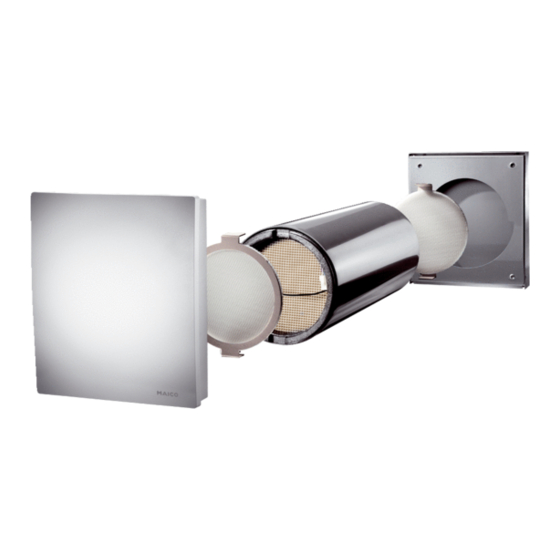
| 5. Produktinformationen Die Stufen geben das Fördervolumen der 5. Produktinformationen Lüftungsgeräte pro Stunde an: 5.1 Produktbeschreibung PP 60 KA PP 60 KL Das PushPull 60 K ist ein Einzelraum- lüftungsgerät mit Wärmerückgewinnung. Das Lüftungsgerät wird direkt in den zu Stufe 1 17 m³/h... -
Seite 11: Technische Daten
(ähnlich RAL 9016). ● Außenabdeckung aus Edelstahl 17 – 55 m³/h Fördervolumen PP 60 KA (PP 60 KA) oder mit Laibungselement aus 17 – 50 m³/h Fördervolumen PP 60 KL Edelstahl / Aluminium (PP 60 KL) ● Mit Luftfilter der Filterklasse G3 zum Wärmerückgewinnungs-... -
Seite 12: Montagevorbereitung
de | 6. Montagevorbereitung Nachdem Innenputz- und Malerarbeiten 6. Montagevorbereitung fertiggestellt sind: ● Rahmen der Innenabdeckung und 6.1 Anforderungen an den Lüftungsgerät PP 60 K-SE einbauen Aufstellungsort [Kap. 7.6 und 7.7] Zulässig ist eine Installation nur: ● Raumluftsteuerung RLS PP-K anbringen ●... - Seite 13 Mindestabstand von der Seite zur Mitte der Wandöffnung von 200 mm. Die Wandöffnung (Kernlochbohrung) muss mindestens 220 mm im Durchmesser betragen. PP 60 KA-SR zusammen mit PP 60 K-SE Die minimale Wandstärke muss 270 mm betragen. Bauseitig bereitzustellendes Werkzeug und Material: ●...
-
Seite 14: Montage (Fachinstallateur)
de | 7. Montage (Fachinstallateur) ● Außenwandmontage: der Fassade ein wasserabweisendes 4 x Dübel und Schrauben, Ø 6 mm Putzsystem an. (Länge und Dübelart je nach ● Bringen Sie die Kernlochbohrung mit Außenwandausführung / Dämmsystem) 1…2 % Neigung nach außen hin an. ●... -
Seite 15: Unterputzdose
7. Montage (Fachinstallateur) | de 5. Keile mit einem Cutter-Messer oder 7.4 Laibungselement PP 60 KL-SR ähnlichem kürzen, damit diese bündig Diese Schritte durchführen, wenn ein zur Innenwand und dem Außenputz PP 60 KL-SR montiert wird. sind. 6. Wandeinbauhülse innen und außen mit 1. - Seite 16 | 7. Montage (Fachinstallateur) 7.5 Außenabdeckung PP 60 KA-SR Diese Schritte durchführen, wenn ein PP 60 KA-SR montiert wird. 1. Gegebenenfalls den Putzschutzdeckel außen entfernen. 6. Rahmen der Außenabdeckung mit Dübeln und Schrauben (Ø 6 mm, Beistellung bauseits) an der Außenwand befestigen.
-
Seite 17: Rahmen Der Innenabdeckung
8. Elektrischer Anschluss (Fachinstallateur) | de 7.6 Rahmen der Innenabdeckung 8. Elektrischer Anschluss PP 60 K-SE (Fachinstallateur) 1. Gegebenenfalls Putzschutzdeckel innen ● Der elektrische Anschluss darf nur von entfernen. Elektrofachkräften gemäß nachfolgenden 2. Neigungswinkel der eingebauten Schaltbildern im Anhang vorgenommen Wandhülse überprüfen. - Seite 18 de | 8. Elektrischer Anschluss (Fachinstallateur) anschließen. Dabei darauf achten, dass ACHTUNG die Lüftungsgeräte am richtigen Sachschaden bei Vertauschen der Steckplatz der Raumluftsteuerung Anschlüssen +12 V und GND (X3 bis X6) angeschlossen sind. Siehe Schließen Sie die Spannungsversorgung auch Schaltbild Seite 21. der Raumluftsteuerung und der Lüftungs- Feuchtesensor kann nur an geräte unbedingt korrekt an.
-
Seite 19: Inbetriebnahme
9. Inbetriebnahme | de 4. Die Ventilator-Anschlussleitung [6.2] Dieses Lüftungsgerät Nummer 1 und durch die Kabeldurchführung für den das korrespondierende Lüftungsgerät Ventilator [6.1] führen. Nummer 2 am Stecker X5 gehen in Entfeuchtungsmodus. Lüftungsgerät an 5. Ventilator-Anschlussleitung [6.2] im X3 schaltet auf Abluft. Lüftungsgerät an Rahmen mit der Ventilator-Anschluss- X5 schaltet auf Zuluft. -
Seite 20: Störungsbehebung
de | 10. Störungsbehebung 10. Störungsbehebung GEFAHR Filterwechselanzeige Lebensgefahr durch Stromschlag! An der Raumluftsteuerung werden Sie wie Schalten Sie die Sicherung im Sicherungs- kasten aus und sichern Sie diese gegen folgt zum Luftfilterwechsel aufgefordert. Wiedereinschalten. Bringen Sie ein Warn- ● LEDs der eingestellten Betriebsart und schild am Sicherungskasten an. -
Seite 21: Zubehör Und Ersatzteile
11. Zubehör und Ersatzteile | de 1. Innenabdeckung [8] des Lüftungs- 11. Zubehör und Ersatzteile gerätes abnehmen. 2. Innenfilter [5] entfernen. Zubehör / Ersatzteil Artikel-Nr. 3. Einschub [4] inklusive Wärmetauscher Ersatz-Luftfilter PPF G3, und EC-Ventilator mithilfe der Draht- 0093.0169 Filterklasse G3, 2 Stück schlinge herausnehmen. -
Seite 22: Reinigung Der Innenabdeckung
de | 13. Demontage und Entsorgung Entsorgen Sie das Gerät nach Ablauf seiner 12.2 Reinigung der Innenabdeckung Lebensdauer nach den in Ihrem Land geltenden Umweltrichtlinien und Vorschriften. WARNUNG 14. Schaltbilder Gefahr durch Stromschlag! Schalten Sie die Sicherung im Sicherungs- Platine Lüftungsgeräte PushPull 60 K kasten aus und sichern Sie diese gegen Wiedereinschalten. - Seite 23 14. Schaltbilder | de Feuchtesensor PPH-K auf der Platine des Lüftungsgeräts Anschluss Lüftungsgeräte PushPull 60 K an Raumluftsteuerung RLS PP-K...
-
Seite 24: Scope Of Delivery
| Unit overview, Fig. A, B, C, D Unit overview, Fig. A, B, C, D Table of contents Fig. A, PP 60 KA-SR and PP 60 K-SE 1. Scope of delivery ........22 External cover 2. Safety instructions ........23 External cover frame 3. -
Seite 25: Wall Insulation Sleeve
2. Safety instructions | gb Please separately order one humidity PushPull 60 KL-SR shell kit sensor per RLS PP-K room air control. Soffit element Article no. 0095.0206 ● 2. Safety instructions Soffit element made from stainless steel/aluminium Read these mounting and ●... -
Seite 26: Intended Use
Clean the filters every 2-3 220 mm core hole diameter. months. Change all air filters when the filter change display 2.2 Predictable misuse on the room air control Maico is not liable for appears. damages caused by improper use (use other than intended use). - Seite 27 2. Safety instructions | gb Cleaning, maintenance particularly DIN VDE 0100 with the corresponding parts. Disconnect the ventilation unit from the mains supply before Modifications and alterations carrying out any cleaning and to the unit are not permitted maintenance work - switch off and release the manufacturer the mains fuse at the fuse from any guarantee and...
-
Seite 28: Regulations For Operation With Fireplaces
gb | 3. Environmental protection ● Only operate the unit when the extraction of exhaust gas completely assembled and with from the air-ventilated the voltage and frequency shown fireplaces is monitored by on the rating plate. special safety equipment. In the case of air-ventilated Regulations for operation fireplaces for liquid or... - Seite 29 The levels indicate the hourly air volume of The LEDs [21] next to the key the ventilation units: show the operating mode selected PP 60 KA PP 60 KL at present: Heat recovery operating mode: Level 1 17 m³/h 17 m³/h...
-
Seite 30: Product Information
● External cover made from stainless steel The PushPull 60 K is a single-room (PP 60 KA) or with soffit element made ventilation unit with heat recovery. The from stainless steel / aluminium ventilation unit is installed directly in the... -
Seite 31: Preparations For Mounting
For dimensions and characteristic curves, K-SE ventilation unit [Chap. 7.6 and 7.7] see catalogue and/or website ● Fit RLS PP-K room air control and (maico-ventilatoren.com) connect [Chap. 8]. 6. Preparations for mounting 6.3 Dimensions 6.1 Requirements at the installation Dimensions of internal cover and... - Seite 32 | 6. Preparations for mounting PP 60 KA-SR together with PP 60 K-SE Dimensions of soffit element [mm] PP 60 KL-SR Dimensions of hole in wall and spacing Dimensions of external cover and frame to ceiling / side [mm]...
-
Seite 33: Mounting (Specialist Installer)
7. Mounting (specialist installer) | gb ● Tools and material to be provided Make sure there is sufficient working by the customer: space in front of the unit, e.g. for filter changing. ● Core hole drill and drill bit ● In order to avoid any smells, there 220 mm in diameter should be sufficient space between the... - Seite 34 gb | 7. Mounting (specialist installer) 2. Produce core drill hole. Observe a 9. If the wall insulation sleeve protrudes 1…2 % inclination (towards the more than 20 mm out of the external external wall) so that the wall (incl. plaster), shorten wall condensation produced can flow out insulation sleeve at external wall.
- Seite 35 10. Have a specialist insulate space between soffit duct and external plastering. 7.5 PP 60 KA-SR external cover Undertake these steps if a PP 60 KA-SR is being mounted. 1. Remove plaster protective cover on outside if necessary.
-
Seite 36: Electrical Connection (Specialist Installer)
gb | 8. Electrical connection (specialist installer) 9. Secure external cover to frame with 8. Electrical connection screw supplied. (specialist installer) 7.6 Frame of PP 60 K-SE internal ● Only qualified electricians are permitted cover to make the electrical connections, in compliance with the wiring diagrams 1. - Seite 37 8. Electrical connection (specialist installer) | gb 5. Connect one control cable, max. NOTICE length of 20 m, to the room air control Material damage if the +12 V and GND per PP 60 K ventilation unit. Ensure connections are swapped by mistake that the ventilation units are Be sure to correctly connect the power connected to the right room air control...
-
Seite 38: Commissioning
gb | 9. Commissioning 4. Guide the fan connection cable [6.2] number 2 on connector X5 switch to through the cable feedthrough for the dehumidification mode. Ventilation fan [6.1]. unit at X3 switches to exhaust air. Ventilation unit at X5 switches to 5. -
Seite 39: Accessories And Spare Parts
11. Accessories and spare parts | gb ● Check whether the mains fuse has failed. Switch on if necessary. Ventilation unit No mains voltage. does not switch ● Check whether the mains fuse has failed. Switch on if necessary. WARNING Nothing happens Humidity sensor not Danger from electric shock! -
Seite 40: Cleaning, Maintenance
gb | 12. Cleaning, maintenance lugs. The pasting frame must be 12. Cleaning, maintenance facing the slide-in module. 7. Place internal filter [5] on slide-in 12.1 Filter cleaning / change module [4] and turn down pasting lugs. The pasting frame must be The filters must be blown out every 2-3 facing the slide-in module. -
Seite 41: Disassembly And Disposal
13. Disassembly and disposal | gb 13. Disassembly and disposal 14. Wiring diagrams PCB for PushPull 60 K ventilation units Packaging Dispose of the packaging material in compliance with the regulations valid in the country where you are. Air filter Dispose of the air filter according to local regulations. - Seite 42 gb | 14. Wiring diagrams Connection for PushPull 60 K ventilation units to RLS PP-K room air control...
-
Seite 43: Éléments Fournis
Sommaire fig. A, B, C, D 1. Éléments fournis ......... 41 2. Consignes de sécurité ........ 42 Fig. A, PP 60 KA-SR et PP 60 K-SE Capot extérieur 3. Protection de l'environnement ..... 46 Cadre Capot intérieur 4. Utilisation ............ 46 Filtre extérieur PPF G3... -
Seite 44: Consignes De Sécurité
fr | 2. Consignes de sécurité ● Non compris dans les éléments fournis Kit gros œuvres PushPull 60 KL-SR avec les kits de montage final. Élément d'embrasure ● Réf. 0095.0206 Veuillez commander séparément un capteur d'humidité par commande d'air ● Élément d'embrasure en acier ambiant RLS PP-K. -
Seite 45: Utilisation Conforme
Appareil de ventilation servant à l'insufflation et à 2.2 Erreurs d'application l'évacuation d'air dans des prévisibles pièces individuelles avec Maico décline toute des performances de responsabilité en cas de ventilation de jusqu'à 55 dommages découlant d'une m³/h. utilisation non-conforme. Ne ●... -
Seite 46: Consignes De Sécurité Générales
fr | 2. Consignes de sécurité ● en association avec des une remise en marche hottes d’extraction ou des inopinée. systèmes d’aspiration de Livraison laboratoire. Vérifiez l'absence d'avaries ● Ne pas installer la sur l'emballage et l'appareil. commande d'air ambiant et Ne mettez pas un appareil l'appareil à... -
Seite 47: Risque D'électrocution
2. Consignes de sécurité | fr fabricant de toute Faites exclusivement fonctionner l’appareil complètement responsabilité et garantie. assemblé et à la tension de En cas de dommages service et la fréquence indiquées Les réparations qui ne sont sur la plaque signalétique. pas effectuées dans les règles Directives relatives à... -
Seite 48: Protection De L'environnement
fr | 3. Protection de l'environnement ménagères. Déballez l'appareil. Veuillez ambiant pour des éliminer les matériaux d’emballage dans le combustibles liquides ou respect des prescriptions en vigueur dans gazéiformes ou bien de votre pays. l'installation d'aspiration d'air 4. Utilisation est empêché par des dispositifs de sécurité... -
Seite 49: Informations Produit
Les niveaux indiquent le débit horaire des 5.1 Description du produit appareils de ventilation : Le PushPull 60 K est un appareil de PP 60 KA PP 60 KL ventilation individuel à récupération de chaleur. Le ventilateur est monté directement dans la pièce à aérer (sans Niveau 17 m³/h... -
Seite 50: Équipements
2 à 3 mois 5.2 Versions et de les remplacer conformément aux indications de l'affichage correspondant. ● PP 60 KA : exécution confort avec capot ● extérieur en acier inoxydable. Inutile d'ajuster l'installation de ventilation. -
Seite 51: Préparation Au Montage
PushPull 60 KA-SR [Chap. 7.5]. Pour les dimensions et les courbes caractéristiques, consulter le catalogue ou Une fois le crépi intérieur et les travaux aller sur Internet (maico-ventilatoren.com). de peinture terminés : ● Monter le cadre du capot intérieur et 6. - Seite 52 PP 60 KA-SR capot intérieur [mm] PP 60 K-SE Dimensions Vue latérale [mm] PP 60 KL-SR combiné à PP 60 K-SE Passage de câbles Dimensions Élément d'embrasure [mm] PP 60 KL-SR PP 60 KA-SR combiné à PP 60 K-SE...
- Seite 53 7. Montage (technicien spécialisé) | fr ● Montage sur mur extérieur : Dimensions Trous du mur et écarts par 4 x cheville et vis, Ø 6 mm (longueur et rapport au plafond / côté [mm] type de cheville en fonction du type de Vue intérieure de l'appartement mur extérieur / du système d'isolation) ●...
- Seite 54 fr | 7. Montage (technicien spécialisé) ● Choisissez la position de montage de 3. Introduire la gaine de montage mural façon à éviter tout encrassement et [10] dans le trou de taraudage. Après courant d’air. la pose du crépi, du papier-peint, etc., la gaine de montage mural doit être ●...
- Seite 55 PP 60 KL-SR Ces opérations sont à effectuer dans le Ces opérations sont à effectuer dans le cas du montage d'un PP 60 KA-SR. cas du montage d'un PP 60 KL-SR. 1. Si nécessaire, retirer le couvercle de 1. Poser le canal d'embrasure [15] sur la protection du crépi à...
-
Seite 56: Appareil De Ventilation
fr | 7. Montage (technicien spécialisé) La moitié inférieure plus longue sert de larmier pour l'évacuation du condensat. 8. Insérer le capot extérieur [1] par 3. Utiliser du silicone pour rendre l'avant dans les glissières de guidage étanche le larmier de la gaine de du cadre [2] puis pousser le capot montage mural à... -
Seite 57: Branchement Électrique (Technicien Spécialisé)
8. Branchement électrique (technicien spécialisé) | fr carton. Le cadre en carton doit être DANGER orienté vers le module d'insertion. Risque d’électrocution ! 3. Poser le filtre intérieur G3 [5] (M6 optionnel) sur le module d'insertion [4] Déconnectez le fusible dans la boîte à tout en rabattant les languettes en fusibles et sécurisez-le contre tout carton. - Seite 58 fr | 8. Branchement électrique (technicien spécialisé) 2. À l'aide du schéma de la page 61, 6. Fixer la platine [18] avec le cadre en brancher le câble marron et le bleu du tôle [17] sur la moitié supérieure de la bloc secteur au réseau électrique.
-
Seite 59: Mise En Service
9. Mise en service | fr câble de raccordement du ventilateur (platine de commande). Cet appareil du module d'insertion [4]. de ventilation numéro 1 et son pendant, l'appareil de ventilation 6. Insérer le filtre intérieur [5] et rabattre numéro 2 branché au connecteur X5, les languettes en carton. -
Seite 60: Élimination Des Dysfonctionnements
fr | 10. Élimination des dysfonctionnements 3. Pour la commande des appareils de Dysfonctionnements divers ventilation, voir Chapitre 4, à partir de En cas de dysfonctionnement, consulter la page 46. un électricien qualifié. Les réparations sont exclusivement réservées à des électriciens 10. -
Seite 61: Accessoires Et Pièces De Rechange
11. Accessoires et pièces de rechange | fr ● les diodes du mode de fonctionnement pération de numéro 1, voir chaleur. page 57 et du niveau de ventilation réglés clignotent, par exemple : l'humidité relative au capteur est inférieure à 45 %. Les appareils de ventilation fonctionnent en... -
Seite 62: Démontage Et Élimination
fr | 13. Démontage et élimination Le cadre en carton doit être orienté 13. Démontage et élimination vers le module d'insertion. 8. Pousser le module d'insertion [4] dans Emballage la gaine de montage mural. Éliminez les matériaux d’emballage dans L'échangeur de chaleur doit alors être le respect des directives orienté... -
Seite 63: Schémas De Branchement
14. Schémas de branchement | fr Capteur d'humidité PPH-K sur la platine de 14. Schémas de branchement l'appareil de ventilation Platine Appareils de ventilation PushPull 60 K Platine Commande d'air ambiant RLS PP-K... - Seite 64 fr | 14. Schémas de branchement Raccordement des appareils de ventilation PushPull 60 K à la commande d'air ambiant RLS PP-K...
- Seite 66 Maico Elektroapparate-Fabrik GmbH • Steinbeisstr. 20 • 78056 Villingen-Schwenningen • Germany • Service +49 7720 694 447 • technik@maico.de...