Werbung
Verfügbare Sprachen
Verfügbare Sprachen
Quicklinks
I I I I I MULTIMETRE
I I I I I MULTIMETER
I I I I I MULTIMETER
I I I I I MULTIMETRO
I I I I I MULTIMETRO
FRANCAIS
Notice de fonctionnement
ENGLISH
User's manual
DEUTSCH
Bedienungsanleitung
ITALIANO
Libretto d'Istruzioni
ESPANOL
Manual de Empleo
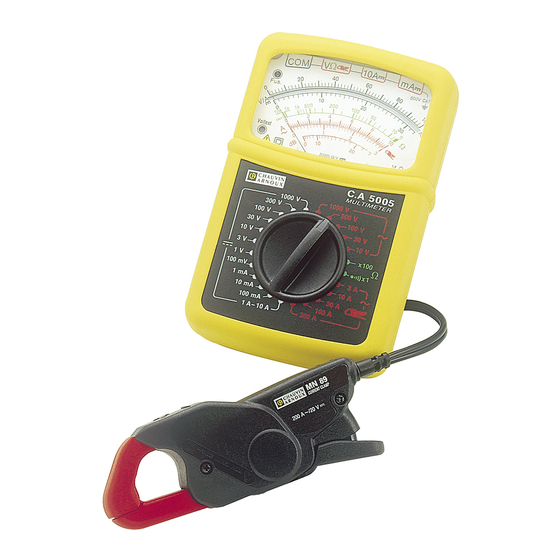
C.A 5005
1
Werbung

Verwandte Anleitungen für Chauvin Arnoux P01.1965.23E


Inhaltszusammenfassung für Chauvin Arnoux P01.1965.23E
- Seite 1 C.A 5005 I I I I I MULTIMETRE I I I I I MULTIMETER I I I I I MULTIMETER I I I I I MULTIMETRO I I I I I MULTIMETRO FRANCAIS Notice de fonctionnement ENGLISH User's manual DEUTSCH Bedienungsanleitung ITALIANO Libretto d'Istruzioni...
- Seite 2 Signification du symbole ATTENTION ! Consulter la notice de fonctionnement avant d'utili- ser l'appareil. Dans la présente notice de fonctionnement, les instructions précédées de ce symbole, si elles ne sont pas bien respectées ou réalisées, peuvent occasionner un accident corpo- rel ou endommager l'appareil et les installations.
- Seite 3 ENGLISH ....................10 DEUTSCH ....................18 ITALIANO ....................26 ESPANOL ....................34 SOMMAIRE Page 1 - Présentation ............3 2 - Description ............4 3 - Tensions continues et alternatives (V et ~) ... 5 4 - Décibels (dB) ............5 5 - Intensités (A et ~) ..........
- Seite 4 2 - DESCRIPTION (Voir dessin en § 12 - ANNEXE) ➀ ➀ ➀ ➀ ➀ BORNES Bornes de sécurité Ø 4 mm I COM : commun, borne recevant le cordon noir I VΩ Ω Ω Ω Ω : borne recevant le cordon rouge pour les tensions, résistances et intensités alternatives avec minipince MN89 I 10 A : borne recevant le cordon rouge pour les calibres 10 A...
- Seite 5 3 - TENSIONS CONTINUES ET ALTERNATIVES I Raccorder les cordons au multimètre et se brancher en parallèle sur le circuit à contrôler. I Lorsque l'ordre de grandeur n'est pas connu, placer le commutateur sur le calibre le plus élevé puis baisser progressivement jusqu'au calibre approprié.
- Seite 6 5 - INTENSITÉS CONTINUES ET ALTERNATIVES Pour les intensités continues : toujours interrompre le circuit à contrôler avant de connecter le multimètre sur le circuit. Si le voyant "Fus" est allumé, changer le(s) fusible(s) défectueux (Rappel : tension minimum de 80 V). Raccorder les cordons au multimètre et se brancher en série dans le circuit avec : - le cordon rouge dans la borne "mA ", jusqu'à...
- Seite 7 A~ avec 10 A 30 A 100 A 300 A minipince MN 89 Echelle Cœff. de lecture x 10 x 10 x 100 Précision 2,5% Protection Assurée avec la minipince MN 89 (1) Calibre limité à 240 A~ maxi par la minipince MN 89 (2) Repérée par "...
- Seite 8 I Degré d'étancheité (NF EN 60529, Ed 92) : indice de protection IP 53 9 - POUR COMMANDER Utiliser les désignations et références ci-dessous. C.A 5005 ..............P01.1965.23E Livré avec une minipince MN 89 et sa notice de fonctionnement, un jeu de 2 cordons à pointe de touche, une pile 9 V...
- Seite 9 Fax : 02 31 64 51 09 11-5 Réparation sous garantie et hors garantie Adressez vos appareils à l'une des agences régionales MANUMESURE, agréées CHAUVIN ARNOUX Renseignements et coordonnées sur demande : Tél. : 02 31 64 51 43 Fax : 02 31 64 51 09 11-6 Réparation hors de France métropolitaine...
- Seite 10 Meaning of the symbol Warning ! Please refer to the User’s Manual before using the instrument. In this User’s Manual, the instructions preceded by the above symbol, should they not be carried out as shown, can result in a physical accident or damage the instrument and the installations.
- Seite 11 CONTENTS Page 1 - Presentation ............11 2 - Description ............12 3 - DC and AC voltages (V DC and AC) ....13 4 - Decibels (dB) ............. 13 5 - Currents (A DC and AC) ........14 6 - Resistances (Ω) ..........15 7 - Continuity sound test [ ] ......
- Seite 12 2 - DESCRIPTION (See drawing in § 12 - APPENDIX) 1 TERMINALS ∅ 4 mm safety terminals I COM: common, terminal that receives the black lead I VΩ Ω Ω Ω Ω : terminal that receives the red lead for voltages, resistances and AC voltages with miniclamp MN 89 I I I I I 10 A DC: terminal that receives the red lead for the 10 A DC ranges I I I I I mA DC: terminal that receives the red lead for the mA DC ranges...
- Seite 13 3 - DC AND AC VOLTAGES I Connect the leads to the multimeter and connect in parallel to the circuit to be tested. I When the order of magnitude is not known, place the switch on the highest range then progressively lower to the appropriate range. I To get the voltage in V, multiply the value read on the appropriate scale by the reading cœfficient shown in the table.
- Seite 14 5 - DC AND AC CURRENTS For DC currents: Always switch off the circuit to test before connecting the multimeter to the circuit. If the «Fus.» light comes on, change the faulty fuse(s) (Reminder: minimum voltage of 80 V). Connect the leads to the multimeter and connect in series to the circuit with: -the red lead in the «mA DC»...
- Seite 15 A~ with 10 A 30 A 100 A 300 A miniclamp MN 89 Scale Reading cœfficient x 10 x 10 x 100 Accuracy 2.5% Protection ensured by the miniclamp MN89 (1) Range limitedto240AAC max by the miniclamp MN 89 (2) Marked with " "...
- Seite 16 I Degree of watertightness (NF EN 60529, ed 92): protection index IP 53 9 - TO ORDER Use the designations and references below. C.A 5005 ..............P01.1965.23E Supplied with a pair of leads with prods, 1 battery 9 V and this User’s manual.
- Seite 17 It is essential that all measuring instruments are regularly calibrated. For checking and calibration of your instrument, please contact our accredited laboratories (list on request) or the Chauvin Arnoux subsidiary or Agent in your country. 11-5 Repair Repairs under or out of guarantee: please return the product to your...
- Seite 18 Bedeutung des Zeichens ACHTUNG ! Beachten Sie vor Benutzung des Gerätes die Hinweise in der Bedienungsanleitung. Falls die in der vorliegenden Bedienungsanleitung nach diesem Zeichen erscheinenden Anweisungen nicht beachtet bzw. nicht ausgeführt werden, können Verletzungen verursacht bzw. das Meßgerät und die Anlage beschädigt werden.
- Seite 19 INHALTSVERZEICHNIS Seite 1 - Gerätevorstellung ..........19 2 - Gerätebeschreibung ......... 20 3 - Gleich- und Wechselspannungen (V und ~) .. 21 4 - Dezibel (dB) ............21 5 - Gleich- und Wechselströme (A und ~) ..22 6 - Widerstandsmessung (Ω) ......... 23 7 - Akustische Durchgangsprüfung [ ] .....
- Seite 20 2 - GERÄTEBESCHREIBUNG (siehe Abb. in Abschn. 12. Anhang) ANSCHLUSSBUCHSEN Ø 4 mm Sicherheitsbuchsen I COM : COMMON bzw. MASSE-Buchse für schwarze Meßleitung I VΩ Ω Ω Ω Ω : Buchse für rote Meßleitung bei Spannungs- und Widerstandsmessungen mit der Minizange MN89 I 10 A : Buchse für rote Meßleitung in den Meßbereichen 10 A I mA...
- Seite 21 3 - GLEICH- UND WECHSELSPANNUNGEN I Meßleitungen in das Multimeter einstecken und zu messende Spannung parallel an der Schaltung abgreifen. I Wenn die Größenordnung einer Meßgröße nicht bekannt ist, den höchsten Meßbereich wählen und stufenweise herunterschalten, bis die geeignete Empfindlichkeit erreicht ist. I Zeigerstellung auf der entsprechenden Skala ablesen und Anzeige mit dem Skalenfaktor gemäß...
- Seite 22 5 - GLEICH- UND WECHSELSTRÖME Bei Gleichströmen: Den Meßkreisstets unterbrechen, bevor das Multimeter in den Stromkreis eingefügt wird. Wenn die Kontrolleuchte «FUS» aufleuchtet, müssen die entsprechende(n) Sicherung(en) ausgewechselt werden ( «FUS» leuchtet nur bei Spannungen von mindestens 80 V im Stromkreis). Das Multimeter in Reihe in den Stromkreis einfügen und die rote Meßleitung je nach Stromstärke in eine der beiden folgenden Buchsen einstecken:...
- Seite 23 A~ mit 10 A 30 A 100 A 300 A Minizange MN 89 Skala Skalenfaktor x 10 x 10 x 100 Genauigkeit 2,5% Überlastschutz Gewährleistet durch Minizange MN89 (1) Bereich beschränkt auf 240A~ max durch Minizange MN89 (2) Markiert durch Symbol " "...
- Seite 24 8-2 Stromversorgung I Eine 9 V-Batterie (Typ 6F22 oder 6LF22 Alkalibatterie) I Batteriebetrieb: ca. 10 000 Messungen von je 10 s mit Alkalibatterie Klimabedingungen I Temperatur: Betrieb: -10° bis +55°C / Lagerung: -40° bis +70°C I Rel. Feuchte: Betrieb: ≤ 90 % / Lagerung: ≤ 95 % I Meereshöhe: Benutzung bei Höhen <...
- Seite 25 11 - WARTUNG, REPARATUR Verwenden Sie für Reparaturen ausschließlich die angegebenen Ersatzteile. Der Hersteller haftet keinesfalls für Unfälle oder Schäden, die nach Reparaturen außerhalb seines Kundendienstnetzes oder durch nicht von ihm zugelassene Reparaturbetriebe entstanden sind. 11-1 Ersetzen der Batterie und der Sicherungen Zu Ihrer Sicherheit müssen die Meßleitungen vor Öffnen des Batteriefachs abgezogen werden.
- Seite 26 Significato del simbolo ATTENZIONE: Leggere le istruzioni d’uso prima di utilizzare lo strumento. Nel presente libretto se le funzioni che sono precedute da questo simbolo non vengono perfettamente rispettate o seguite, è possibile che si verifichino incidenti con danni alle persone, allo strumento o alle installazioni. Significato del simbolo Questo strumento è...
- Seite 27 SOMMARIO Pagina 1 - Presentazione ............ 27 2 - Descrizione ............28 3 - Tensioni continue e alternate (V e ~) ..... 29 4 - Decibel (dB) ............29 5 - Correnti (A e ~) ..........30 6 - Resistenze (Ω) ..........31 7 - Test sonoro di continuità...
- Seite 28 2 - DESCRIZIONE (Vedere disegno pag. 12 - ALLEGATO) 1 MORSETTI Morsetti di sicurezza Ø 4 mm I COM : comune, morsetto a cui si collega il cordone nero. I VΩ Ω Ω Ω Ω : morsetto a cui si collega il cordone rosso per le tensioni, resistenze e correnti alternate con minipinza MN 89 I 10 A : morsetto a cui si collega il cordone rosso per portate 10 A...
- Seite 29 3 - TENSIONI CONTINUE E ALTERNATE I Collegare i cordoni al multimetro e allacciarsi in parallelo al circuito da controllare. I Quando non si conosce l’ordine di grandezza, posizionare il commutatore sulla portata più alta e scendere progressivamente fino a raggiungere la portata adatta. I Per ottenere la tensione in V, moltiplicare il valoreletto sulla relativa scala per il coefficiente di lettura indicato nella tabella seguente.
- Seite 30 5 - CORRENTI CONTINUE E ALTERNATE Per le correnti continue: interrompere sempre il circuito da ill controllare prima di collegarvi il multimetro. Se si accende la spia "Fus", cambiare il/i fusibile/i difettoso/i (Nota: tensione minima di 80 V). Collegare i cordoni al multimetro e allacciarsi in serie al circuito con: - il cordone rosso nel morsetto "mA "...
- Seite 31 A~ con 10 A 30 A 100 A 300 A minipinza MN 89 Scala Cœfficiente di lettura x 10 x 10 x 100 Precisione 2,5% Protezione Garantita dalla minipinza MN 89 (1) Portata limitata a 240 A~ max per la minipinza MN 89 (2) Indicata dalla "...
- Seite 32 9 - PER ORDINARE Utilizzare le descrizioni e i codici di seguito riportati. C.A 5005 ..............P01.1965.23E Fornito con una minipinza MN89 e relativo libretto di istruzioni, un set di 2 cordoni con puntale, una pila 9 Ve libretto di istruzioni.
- Seite 33 11 - MANUTENZIONE Per la manutenzione, utilizzare solo i pezzi di ricambio specificati. Il costruttore non potrà essere ritenuto responsabile di alcun incidente occorso a causa di una riparazione non eseguita dal proprio servizio di assistenza post-vendita o da personale autorizzato. 11-1 Sostituzione della pila e dei fusibili Per la vostra sicurezza, è...
- Seite 34 Significado del símbolo ¡Atención! Consulte el manual de instrucciones antes de utilizar el aparato. Las instrucciones que en el presente manual van precedidas de este símbolo avisan sobre riesgo de accidente y de los consiguientes perjuicios para personas y objetos en caso de no cumplirse las normas indicadas.
- Seite 35 SOMMARIO Página 1 - Presentación ............35 2 - Descripción ............36 3 - Tensiones continuas y alternas (V y ~) ..37 4 - Decibelios (dB) ..........37 5 - Intensidades (A y ~) ........38 6 - Resistencias (Ω) ..........39 7 - Test sonoro de continuidad [ ] ....
- Seite 36 2 - DESCRIPCION (Véase esquema en 12 - ANEXO) BORNES Bornes de seguridad Ø 4 mm I COM : común, borne que recibe el cable negro. I VΩ Ω Ω Ω Ω : borne que recibe el cable rojo para las tensiones, resistencias y intensidades alternas con minipinza MN89 I 10 A : borne que recibe el cable rojo para los calibres 10 A...
- Seite 37 3 - TENSIONES CONTINUAS Y ALTERNAS I Conectar los cables al multímetro y conectar en paralelo al circuito a controlar. I Cuando no se conoce la magnitud, colocar el conmutador al calibre más elevado, a continuación bajar progresivamente hasta el calibre apropiado.
- Seite 38 5 - INTENSIDADES CONTINUAS Y ALTERNAS Para las intensidades continuas: Interrumpirsiempreel circuito ill que ha de controlarse antes de conectar el multímetro al circuito. Si se enciende el indicador «Fus», hay que cambiar el(los) fusible(s) defectuoso(s) (Recordatorio: tensión mínima de 80V). Conectar los cables al multímetro y conectar en serie al circuito con: - el cable rojo en el borne "mA "...
- Seite 39 A~ con 10 A 30 A 100 A 300 A minipinza MN 89 Escala Cœficiente de lectura x 1 x 10 x 10 x 100 Precisión 2,5% Protección Garantita de la minipinza MN 89 (1) Calibre limitado a 240 A~ máx. por la minipinza MN 89 (2) Referenciada por "...
- Seite 40 9 - PARA CURSAR PEDIDO Utilizar las designaciones y referencias que se indican a continuación. C.A 5005 ..............P01.1965.23E Suministrado con un juego de 2 cables con punta de contacto, una pila de 1,5 V y el presente manual de instrucciones.
- Seite 41 11 - MANTENIMIENTO Para el mantenimiento utilizar únicamente los recambios especificados. El fabricante no se responsabiliza por accidentes que sean consecuencia de una reparación que no haya sido efectuada por su Servicio Post-Venta o por un taller concertado. 11-1 Cambiar la pila y los fusibles Para garantizar la seguridad, es preciso desconectar los cables del multímetro para abrir la caja de las pilas.
- Seite 42 12 - ANNEXE / APPENDIX / ANHANG ALLEGATO / ANEXO...