Pilz PNOZ s2 Betriebsanleitung
Inhaltsverzeichnis
Quicklinks
21 394-6NL-06
PNOZ s2
PNOZ s2
21 394-6NL-06
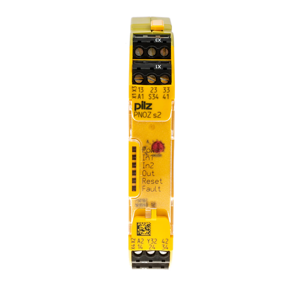
Sicherheitsschaltgerät PNOZ s2
Das Sicherheitsschaltgerät dient dem sicher-
582400011
heitsgerichteten Unterbrechen eines Sicher-
heitsstromkreises.
Das Sicherheitsschaltgerät erfüllt Forderungen
114368651
der EN 60947-5-1, EN 60204-1 und VDE 0113-
1 und darf eingesetzt werden in Anwendungen
mit
Not-Halt-Tastern
Schutztüren
Zu Ihrer Sicherheit
Installieren und nehmen Sie das Gerät nur
547263243
dann in Betrieb, wenn Sie diese Betriebsan-
leitung gelesen und verstanden haben und
Sie mit den geltenden Vorschriften über Ar-
beitssicherheit und Unfallverhütung vertraut
sind.
Beachten Sie die VDE- sowie die örtlichen
Vorschriften, insbesondere hinsichtlich
Schutzmaßnahmen
Durch Öffnen des Gehäuses oder eigen-
mächtige Umbauten erlischt jegliche Ge-
währleistung.
Gerätemerkmale
459983883
Relaisausgänge zwangsgeführt:
– 3 Sicherheitskontakte (S) unverzögert
– 1 Hilfskontakt (Ö) unverzögert
Sichere Trennung der Sicherheitskontakte
von allen anderen Stromkreisen
1 Halbleiterausgang
Anschlussmöglichkeiten für:
– Not-Halt-Taster
– Schutztürgrenztaster
– Starttaster
1 Kontakterweiterungsblock PNOZsigma
über Verbindungsstecker anschließbar
Betriebsarten mit Drehschalter einstellbar
LED-Anzeige für:
Versorgungsspannung
Eingangszustand Kanal 1
Eingangszustand Kanal 2
Schaltzustand Sicherheitskontakte
Startkreis
Fehler
steckbare Anschlussklemmen (wahlweise
Federkraftklemme oder Schraubklemme)
Sicherheitseigenschaften
Das Schaltgerät erfüllt folgende Sicherheitsan-
117575307
forderungen:
Die Schaltung ist redundant mit Selbstüber-
wachung aufgebaut.
Die Sicherheitseinrichtung bleibt auch bei
Ausfall eines Bauteils wirksam.
Bei jedem Ein-Aus-Zyklus der Maschine wird
automatisch überprüft, ob die Relais der Si-
cherheitseinrichtung richtig öffnen und
schließen.
114378891
Das Gerät hat eine elektronische Sicherung.
PNOZ s2 safety relay
The safety relay provides a safety-related inter-
ruption of a safety circuit.
The safety relay meets the requirements of
EN 60947-5-1, EN 60204-1 and VDE 0113-1
and may be used in applications with
E-STOP pushbuttons
Safety gates
For your safety
Only install and commission the unit if you
have read and understood these operating
instructions and are familiar with the applica-
ble regulations for health and safety at work
and accident prevention.
Ensure VDE and local regulations are met,
especially those relating to safety.
Any guarantee is rendered invalid if the hous-
ing is opened or unauthorised modifications
are carried out.
Unit features
Positive-guided relay outputs:
– 3 safety contacts (N/O), instantaneous
– 1 auxiliary contact (N/C), instantaneous
Safe separation of safety contacts from all
other circuits
1 semiconductor output
Connection options for:
– E-STOP pushbutton
– Safety gate limit switch
– Reset button
A connector can be used to connect 1
PNOZsigma contact expander module
Operating modes can be set via rotary switch
LED indicator for:
Supply voltage
Input status, channel 1
Input status, channel 2
Switch status, safety contacts
Reset circuit
Error
Plug-in connection terminals (either spring-
loaded terminal or screw terminal)
Safety features
The relay meets the following safety require-
ments:
The circuit is redundant with built-in self-
monitoring.
The safety function remains effective in the
case of a component failure.
The correct opening and closing of the safety
function relays is tested automatically in
each on-off cycle.
The unit has an electronic fuse.
- 1 -
Bloc logique de sécurité PNOZ s2
Le bloc logique de sécurité sert à interrompre
en toute sécurité un circuit de sécurité.
Le bloc logique de sécurité satisfait aux exigen-
ces des normes EN 60947-5-1, EN 60204-1 et
VDE 0113-1 et peut être utilisé dans des appli-
cations avec des
boutons-poussoirs de arrêt d'urgence
protecteurs mobiles
Pour votre sécurité
Vous n'installerez l'appareil et ne le mettrez
en service qu'après avoir lu et compris le
présent manuel d'utilisation et vous être fa-
miliarisé avec les prescriptions en vigueur
sur la sécurité du travail et la prévention des
accidents.
Respectez les normes locales ou VDE, parti-
culièrement en ce qui concerne la sécurité.
L'ouverture de l'appareil ou sa modification
annule automatiquement la garantie.
Caractéristiques de l'appareil
Sorties de relais à contact lié :
– 3 contacts de sécurité (F) instantanés
– 1 contact d'information (O) instantané
Séparation galvanique entre les contacts de
sécurité de tous les autres circuits
1 sortie statique
Raccordements possibles pour :
– poussoir d'arrêt d'urgence
– interrupteur de position
– poussoir de réarmement
1 bloc d'extension de contacts PNOZsigma
raccordable par connecteur
Modes de fonctionnement réglables par sé-
lecteur
LED de visualisation pour :
tension d'alimentation
Etat d'entrée canal 1
Etat d'entrée canal 2
Etat de commutation des contacts de sécu-
rité
circuit de réarmement
Erreur
Borniers débrochables (au choix avec rac-
cordement à ressort ou à vis)
Caractéristiques de sécurité
Le relais satisfait aux exigences de sécurité
suivantes :
La conception interne est redondante avec
une autosurveillance.
Le dispositif de sécurité reste actif, même en
cas de défaillance d'un composant.
L'ouverture et la fermeture correctes des re-
lais internes sont contrôlées automatique-
ment à chaque cycle marche/arrêt de la
machine.
L'appareil est équipé d'une sécurité électro-
nique.
Inhaltsverzeichnis

Verwandte Anleitungen für Pilz PNOZ s2


Inhaltszusammenfassung für Pilz PNOZ s2
- Seite 1 PNOZ s2 21 394-6NL-06 PNOZ s2 Sicherheitsschaltgerät PNOZ s2 PNOZ s2 safety relay Bloc logique de sécurité PNOZ s2 582400011 Das Sicherheitsschaltgerät dient dem sicher- The safety relay provides a safety-related inter- Le bloc logique de sécurité sert à interrompre heitsgerichteten Unterbrechen eines Sicher- ruption of a safety circuit.
- Seite 2 Blockschaltbild/Klemmenbelegung Block diagram/terminal configuration Schéma de principe/affectation des bornes *Sichere Trennung nach EN 60947-1, 6 kV *Safe separation in accordance with * Séparation galvanique selon la norme 569781643 Mitte: Frontansicht mit Abdeckung EN 60947-1, 6 kV EN 60947-1, 6 kV Rechts: Frontansicht ohne Abdeckung Centre: Front view with cover Schéma du milieu : vue frontale avec capot de...
- Seite 3 Montage Installation Montage 419461003 Grundgerät ohne Kontakterweiterungs- Install base unit without contact expander Installer l'appareil de base sans bloc d'ex- block montieren: module: tension de contacts : Stellen Sie sicher, dass der Abschluss- Ensure that the plug terminator is inserted at Assurez-vous que la fiche de terminaison est stecker seitlich am Gerät gesteckt ist.
- Seite 4 Betriebsartenwahlschalter "mo- automatischer, manueller Start/ überwachter Start steigende Flan- überwachter Start fallende Flanke/ de"/ automatic, manual reset/ monitored reset falling edge/ operating mode selector switch réarmement automatique, manuel monitored reset rising edge/ réarmement auto-contrôlé avec "mode"/ réarmement auto-contrôlé avec front descendant sélecteur de mode de marche front montant "mode"...
-
Seite 5: Betrieb
Betrieb Operation Exploitation 557883787 Das Gerät ist betriebsbereit, wenn die LED Po- The unit is ready for operation when the Power L'appareil est prêt à fonctionner lorsque la LED wer permanent leuchtet. LED is permanently lit. Power reste allumée en permanence. LEDs zeigen den Status und Fehler während LEDs indicate the status and errors during op- Les LEDs indiquent l'état et les erreurs lors du... - Seite 6 Technische Daten Technical details Caractéristiques techniques Elektrische Daten Electrical data Données électriques Versorgungsspannung Supply voltage Tension d'alimentation Versorgungsspannung U Supply voltage U Tension d'alimentation U 24 V Spannungstoleranz Voltage tolerance Plage de la tension d'alimentation -15 %/+10 % Leistungsaufnahme bei U Power consumption at U Consommation U 2,0 W...
- Seite 7 Zeiten Times Temporisations Einschaltverzögerung Switch-on delay Temps de montée bei automatischem Start typ. with automatic reset typ. pour un réarmement automatique 75 ms env. bei automatischem Start max. with automatic reset max. pour un réarmement automatique 250 ms max. bei automatischem Start nach with automatic reset after power on pour un réarmement automatique 75 ms...
-
Seite 8: Caractéristiques
Bevollmächtigter: Norbert Fröhlich, Pilz GmbH Authorised representative: Norbert Fröhlich, Représentant : Norbert Fröhlich, Pilz GmbH & & Co. KG, Felix-Wankel-Str. 2, 73760 Ostfil- Pilz GmbH & Co. KG, Felix-Wankel-Str. 2, Co. KG, Felix-Wankel-Str. 2, 73760 Ostfildern,... - Seite 9 21 394-6NL-06 PNOZ s2 21 394-6NL-06 PNOZ s2 Dispositivo de seguridad PNOZ s2 Modulo di sicurezza PNOZ s2 Veiligheidsrelais PNOZ s2 582400011 El dispositivo sirve para la interrupción orienta- Il modulo di sicurezza consente l'interruzione Het veiligheidsrelais dient om een veiligheids- da a la seguridad de un circuito de corriente de sicura di un circuito di sicurezza.
- Seite 10 Diagrama de bloques/Asignación de Schema a blocchi/schema di collega- Blokschema/klembezetting bornes mento dei morsetti 569781643 *Separación segura según EN 60947-1, 6 kV *Separazione sicura secondo EN 60947-1, 6 kV * Veilige scheiding volgens EN 60947-1, 6 kV Centro: Vista frontal con cubierta Al centro: vista frontale con copertura Midden: Vooraanzicht met afscherming Derecha: Vista frontal sin cubierta...
-
Seite 11: Montaje
Montaje Montaggio Montage 419461003 Montaje del dispositivo base sin bloque de Montaggio dispositivo base senza modulo di Basisrelais zonder contactuitbreidingsrelais ampliación de contactos: espansione contatti: monteren: Asegúrese de que la clavija de terminación accertarsi che sia inserito il connettore termi- Zorg dat de afsluitconnector op de zijkant se ha enchufado en el lateral del dispositivo. - Seite 12 selector de modos de funciona- rearme automático, manual/ rearme supervisado, flanco rearme supervisado, flanco de- miento "mode"/ start automatico, manuale/ ascendente/ scendente/ selettore modalità operative "mo- automatische, handmatige start start controllato fronte in salita/ start controllato fronte in discesa de"/ bewaakte start met stijgende flank bewaakte start met dalende flank Bedrijfsmoduskeuzeschakelaar...
-
Seite 13: Funzionamento
Funcionamiento Funzionamento Bedrijf 557883787 El dispositivo está listo para el servicio cuando Il dispositivo è pronto all'uso quando il LED Het apparaat is bedrijfsklaar, als de LED "Po- el LED "POWER" permanece encendido. Power resta sempre illuminato. wer" permanent oplicht. Los LED indican el estado y los errores durante I LED indicano lo stato e gli eventuali guasti/er- LED's geven de status en fouten tijdens het be-... - Seite 14 Datos técnicos Dati tecnici Technische gegevens Datos eléctricos Dati elettrici Elektrische gegevens Tensión de alimentación Tensione di alimentazione Voedingsspanning Tensión de alimentación U Tensione di alimentazione U Voedingsspanning U 24 V Tolerancia de tensión Tolleranza di tensione Spanningstolerantie -15 %/+10 % Consumo de energía con U Potenza assorbita con U Opgenomen vermogen bij U...
- Seite 15 Tiempos Tempi Tijden Retardo a la conexión Ritardo all'eccitazione Inschakelvertraging con rearme automático típ. con start automatico tipo Bij automatische start ca. 75 ms con rearme automático máx. con start automatico max. Bij automatische start max. 250 ms con rearme automático después de con start automatico secondo ali- Bij automatische start na netinscha- 75 ms...
- Seite 16 Internet bile in Internet all'indirizzo www.pilz.com Gevolmachtige: Norbert Fröhlich, Pilz GmbH & www.pilz.com. Mandatario: Norbert Fröhlich, Pilz GmbH & Co. Co. KG, Felix-Wankel-Str. 2, 73760 Ostfildern, Apoderado: Norbert Fröhlich, Pilz GmbH & Co. KG, Felix-Wankel-Str. 2, 73760 Ostfildern, Ger- Duitsland KG, Felix-Wankel-Str.