Danfoss AMV213 Bedienungsanleitung
Inhaltsverzeichnis
Verfügbare Sprachen
Verfügbare Sprachen
Quicklinks
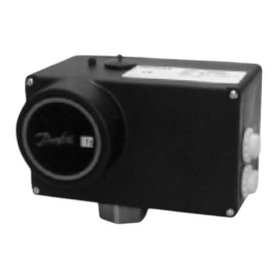
Elektrischer Stellantrieb
Electrical Actuator
AMV213 / AME213
mit Sicherheitsfunktion
with Safety Function
AMV210 / AME210
Bedienungsanleitung / Operating Instructions
AMV(E)210, 213 /
VIM2, VIU2
Seite 2
Page 24
AMV(E)210, 213 /
VIS2
Danfoss IWK
Regler GmbH
600 000 7072
Ausgabe 2 / 6.02
VI.AB.I2.5B
AMV(E)210, 213 /
AIQM, V63M
Kapitel
Inhaltsverzeichnis

Verwandte Anleitungen für Danfoss AMV213


Inhaltszusammenfassung für Danfoss AMV213
- Seite 1 Elektrischer Stellantrieb Seite 2 Electrical Actuator Page 24 Danfoss IWK AMV213 / AME213 Regler GmbH mit Sicherheitsfunktion with Safety Function 600 000 7072 Ausgabe 2 / 6.02 AMV210 / AME210 VI.AB.I2.5B Bedienungsanleitung / Operating Instructions AMV(E)210, 213 / AMV(E)210, 213 /...
-
Seite 2: Inhaltsverzeichnis
8.1 Stellantrieb AMV210, AME210 ......20 8.2 Stellantrieb AMV213, AME213 ......20 8.3 Stellantrieb AME210, AME213 . -
Seite 3: Allgemeine Angaben
Verwendung und Inbetriebnahme nach der für das Gerät gültigen Montage-, In- Der elektrische Stellantrieb ist ein- betriebnahme und Wartungsvor- setzbar für Danfoss-Durchgangs- schrift voraus. ventile in den Nennweiten DN 15 – 50 und für die Nenn- drücke PN 16/25. Die technischen Daten auf den Ty- penschildern Abschnitt 3.3 angegebenen Daten... -
Seite 4: Gerätebeschreibung
Gerätebeschreibung 3 Gerätebeschreibung 3.1 Aufbau Hubbegrenzungs- schraube Hubanzeige Schubstange Mechanische Handverstellung AMV(E)210 Stellhubsignal eines Poten- 3.2 Beschreibung tiometers verglichen. Aus der Dif- Die Antriebseinheit besteht aus ferenz dieser Signale wird ein einem Stirnradgetriebe mit einem Dreipunkt-Schritt-Signal zur An- Synchronmotor. Die Umformung steuerung des Synchronmotors der Drehbewegung in eine axiale abgeleitet. -
Seite 5: Technische Daten
Gerätebeschreibung 3.3 Technische Daten AMV210 AMV213 AME210 AME213 Sicherheitsfunktion Stellzeit s/mm Stellkraft Spannungsversorgung 230 V 24 V +10 % -15 % +10 % -15 % 60 Hz 50/60 Hz Leistungsaufnahme Eingangssignal Dreipunkt-Schritt- 0(4)–20 mA Signal 0(2)–10 V 230 V, 50/60 Hz Ausgangsignal –... -
Seite 6: Abmessungen
Ventiltypen für AMV(E)210, 213 3.4 Abmessungen SW 36 M34x1,5 4 Ventiltypen für AMV(E)210, 213 Der elektrische Stellantrieb AMV(E)210, 213 kann auf folgende Ventile mon- tiert werden: Ventiltyp VIM2, VIU2 VIS2 AIQM V63M Beschreibung Motordurch- Motordurch- Volumen- gangsventil gangsventil für stromregler mit Dampf Motorventil 15 - 50... -
Seite 7: Montage
Montage 5 Montage 5.1 Zulässige Einbaulagen VIM2 Schutzart AIQM Stellantrieb IP 52 Schutzart Stellantrieb IP 54 vorzugsweise AIQM mögliche Schutzart Einbaulage Stellantrieb IP 52 VIM2 Schutzart Stellantrieb IP 54 VIS2 max. 200 °C Schutzart Stellantrieb IP 52... -
Seite 8: Montage Des Stellantriebs Auf Das Ventil
Montage 5.2 Montage des Stellantriebs 3. Kreuzschlitzschrauben (4x) auf das Ventil lösen und Deckel abnehmen. Vor der Montage beachten: Gefahr durch Stromschlag! Bei unsachgemäßer Handha- bung besteht Lebens- oder Ver- letzungsgefahr. Stellantrieb kann beschädigt werden. Bei elektrisch angeschlossenem Stellantrieb Montage Spannungsversorgung abschal- ten. -
Seite 9: Elektrischer Anschluss
Montage 5.3 Elektrischer Anschluss Gefahr durch Stromschlag! Bei unsachgemäßer Handha- bung besteht Lebens- oder Ver- letzungsgefahr. Vor dem Anschluss der Leitungen unbedingt Spannungsversorgung abschalten. Durchführung elektrischen Anschlusses nur durch Elektro- fachkraft. 1. Deckel demontieren siehe Abschnitt 5.2, Punkt 3 2. Die Netzversorgungs- spannung überprüfen. -
Seite 10: Anschlusspläne
Montage 5.4 Anschlusspläne Der Anschlussplan im Deckel ist maßgebend. Anschlussplan AMV210 Anschlussplan Endschalter Anschlussplan AMV213 (Zusatzausrüstung für AMV2..) - Seite 11 Montage Eingang Ausgangs- Regler signal, proportional Stellhub Anschlussplan AME210 AME 213 Ausgangs- Eingang Regler signal, proportional Stellhub Anschlussplan AME213...
-
Seite 12: Mechanische Hubeinstellung
Mechanische Hubeinstellung durch: 6 Mechanische Hubein- stellung AMV213, AME213 Das Ventil schließt (VIU2 öff- Der Hub des elektrischen Stellan- net) automatisch bei abge- triebs (Maximalhub 15 mm) muss schalteter Spannungsversor- nach der Montage dem Ventilhub gung, weiter mit 3. angepasst werden. - Seite 13 Mechanische Hubeinstellung 3. Hubanzeige auf 0 justieren 5. Hubbegrenzungsschraube bis zum Anschlag nach rechts eindrehen justieren 4. Abdeckschraube heraus- schrauben ➻ ➻ ➻ ➻ Hub des Stellantriebs ist auf 0 mm eingestellt T1 Ventilhübe VIM2, AIQM, VIS2, VIU2 Nenn- weite VIM2 Ventilhub AIQM...
- Seite 14 Mechanische Hubeinstellung 6. Aus der Tabelle T1 die 6.2 Ventil AIQM5 „Anzahl der Umdrehungen Vorgehensweise zunächst Hubbegrenzungsschraube“ identisch wie bei den Ventilen ablesen. VIG2, siehe Abschnitt 6.1. 7. Hubbegrenzungsschraube um Unter Punkt 7 müssen die Anzahl diese Anzahl Umdrehungen der erforderlichen Umdrehungen nach links herausdrehen Hubbegrenzungsschraube aus den Einstellkennlinien (siehe...
-
Seite 15: Einstellkennlinien V63M
Mechanische Hubeinstellung 6.3 Einstellkennlinien AIQM5 DN 15 Kvs 2,5 m³/h DN 15 Kvs 1,6 m³/h Beispiel Umdrehungen Umdrehungen Hubbegrenzungsschraube Hubbegrenzungsschraube DN 15 Kvs 4 m³/h DN 20 Kvs 6,3 m³/h / DN 25 Kvs 8 m³/h Max. Volumenstrom DN 25 Max. -
Seite 16: Einstellungen Ame210, Ame213
Einstellungen AME210, AME213 7 Einstellungen AME210, AME213 Vor der Inbetriebnahme müssen die Einstellungen für die Ein-, Ausgangssi- gnale und der Abgleich für die Endlagen durchgeführt werden. 7.1 Übersicht Einstellung DIP-Schalter 2 3 4 5 6 7 8 2 3 4 5 6 7 8 Ohne Funktion Ohne Funktion... -
Seite 17: Einstellung Eingangsignal
Einstellungen AME210, AME213 7.2 Einstellung Eingangsignal 7.3 Einstellung Ausgangssignal Das Ausgangsignal 0(2) - 10 V ist proportional dem Stellhub. Offset Aus- gangsignal 0 - 10 V 2 3 4 5 6 7 8 2 - 10 V 2 3 4 5 6 7 8 Eingangs- signal... -
Seite 18: Zuordnung Der Wirkrichtung Zum Ein-, Ausgangssignal
Einstellungen AME210, AME213 7.4 Zuordnung der Wirkrichtung zum Ein-, Ausgangssignal Ventil: VIU2 Ventile: VIM2, VIS2, AIQM 2 3 4 5 6 7 8 2 3 4 5 6 7 8 20 mA 20 mA 10 V 10 V Ein-, Ein-, Ausgang- Ausgang- signal... -
Seite 19: Einstellung Der Endlagen
Einstellungen AME210, AME213 7.5 Einstellung der Endlagen Während Abgleichvor- gangs blinkt die rote LED Nach der Durchführung der Hub- sie wird am Ende ausgeschal- einstellung (siehe Abschnitt 6) tet. müssen die Endlagen „Ventil AUF“ und „Ventil ZU“ noch mit den Die Einstellungen sind abge- Strom-, Spannungswerten schlossen,... -
Seite 20: Handverstellung
8.1 Stellantrieb AMV210, AME210 Handverstellung erfolgt durch dre- hen des Drehknopfes: Schubstange des Stellan- triebs einfahren VIM2, VIS2, VIU2 AIQM 8.2 Stellantrieb AMV213, AME213 Die Handverstellung kann nach demontieren des Deckels mittels eines Innensechskantschlüssels SW 4 erfolgen. VIM2 VIU2 VIS2 AIQM Drehrichtung siehe unter 8.1. -
Seite 21: Stellantrieb Ame210, Ame213
Handverstellung 8.3 Stellantrieb AME210, Schubstange des Stellan- AME213 triebs ausfahren Bei diesen Stellantrieben kann die Handverstellung bei demontiertem Deckel auch elektrisch durchge- führt werden. VIM2 VIU2 VIS2 AIQM durch Einstellung des Schal- ters S2 Schubstange des Stellan- triebs einfahren Schubstan- ge ausfahren 2 3 4 5 6 7 8... -
Seite 22: Störungshinweise
Störungshinweise 9 Störungshinweise 9.1 Störung, Ursache, Maßnahme Störung Mögliche Ursache Maßnahme Keine Funktion des Netzspannung ausge- Netzspannung über- Stellantriebs schaltet prüfen kein Steuersignal von Regeleinrichtung elektrischen überprüfen Regeleinrichtung Sicherheitseinrich- Anlage, Sicherheits- tung STB, STW oder einrichtung überprü- SDB hat angespro- chen Montagehilfe (Stift) -
Seite 23: Störungsanzeige Stellantriebe Ame210, 213
Störungshinweise 9.2 Störungsanzeige Stellantriebe AME210, 213 Eine Störung kann angezeigt werden durch: 2. das Ausgangsignal >11V die Leuchtdioden (Klemmen 7 (+) und 5), wenn der Schalter folgen- de Stellung hat: Störungsan- zeige >11V 2 3 4 5 6 7 8 Störungsanzeige Störung Maßnahme... - Seite 46 Danfoss IWK Regler GmbH Postfach 1121, D-76288 Stutensee Lorenzstraße, D-76297 Stutensee Tel.: +49 (0) 0 72 44 / 7205-0 Fax.: +49 (0) 0 72 44 / 7205- 311 E-mail: DEBC0043@danfoss.com www.iwk.danfoss.de...