Werbung
Verfügbare Sprachen
Verfügbare Sprachen
Quicklinks
Programmable Controllers
Installation Manual for Positioning
Modules LD75P4, LD75D4
Art.no.: ENG, Version A, 09062011
Safety Information
For qualified staff only
This manual is only intended for use by properly trained and qualified electri-
cal technicians who are fully acquainted with automation technology safety
standards. All work with the hardware described, including system design,
installation, setup, maintenance, service and testing, may only be performed
by trained electrical technicians with approved qualifications who are fully
acquainted with the applicable automation technology safety standards and
regulations.
Proper use of equipment
The programmable controllers (PLC) of the MELSEC L series are only intended
for the specific applications explicitly described in this manual or the manuals
listed below. Please take care to observe all the installation and operating
parameters specified in the manual. All products are designed, manufactured,
tested and documented in agreement with the safety regulations. Any modi-
fication of the hardware or software or disregarding of the safety warnings
given in this manual or printed on the product can cause injury to persons or
damage to equipment or other property. Only peripherals and expansion
equipment specifically recommended and approved by Mitsubishi Electric
may be used with the programmable controllers of the MELSEC L series. Any
other use or application of the products is deemed to be improper.
Relevant safety regulations
All safety and accident prevention regulations relevant to your specific appli-
cation must be observed in the system design, installation, setup, mainte-
nance, servicing and testing of these products.
In this manual special warnings that are important for the proper and safe use
of the products are clearly identified as follows:
DANGER:
P
Personnel health and injury warnings.
Failure to observe the precautions described here can result
in serious health and injury hazards.
E
CAUTION:
Equipment and property damage warnings.
Failure to observe the precautions described here can result
in serious damage to the equipment or other property.
Further information
The following manuals contain further information about the module:
● Instruction leaflet "Before Using the Product" for LD75P4 and LD75D4
● MELSEC L Positioning Module User's Manual
● MELSEC L CPU Module User's Manual
(Hardware Design, Maintenance and Inspection)
● MELSEC-Q L Programming Manual
● Safety Guidelines for MELSEC L CPU
These manuals are available free of charge through the internet
(www.mitsubishi-automation.com).
If you have any questions concerning the installation, configuration or opera-
tion of the equipment described in this manual, please contact your relevant
sales office or department.
Overview of the Modules
Item
LD75P4
LD75D4
No. of control axes
4
Pulse output system
Open collector
Differential driver
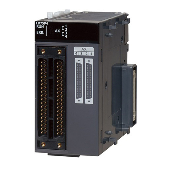
External Dimensions and Part Names
DIN rail
centre
4
³
95
All dimensions are in "mm".
·
LD75P4
·
LD75D4
»
»
¿
¿
·
´
·
No.
Description
³
DIN rail mounting hook
·
Module joint lever (for connecting two modules)
Displays the operation status of the module
b Normal operation
RUN
Hardware failure
Watch dog timer error
Displays the error status of the module
b Operation error
ERR.
v Error on the corresponding axis
Status
»
LED
Normal operation
Displays the status of the corresponding axes
AX1
b The corresponding axis is operating.
AX2
v Error on the corresponding axis
AX3
AX4
The corresponding axis is stopped or on
standby.
All
b Hardware failure
LEDs
2 x 40-pin connector of I/O interface
¿
(AX1 = axis 1, AX2 = axis 2, AX3 = axes 3, AX4 = axis 4)
´
Serial number plate
²
Differential driver common terminal (
LD75D4 only)
b: LED ON, v: LED flashing,
: LED OFF
Installation and Wiring
P
DANGER
Turn off all phases of the power supply for the PLC and other external
sources before starting the installation or wiring work.
E
CAUTION
● Use the product in the environment within the general specifications
described in the MELSEC L CPU Module User's Manual. Never use the
product in areas with dust, oily smoke, conductive dusts, corrosive or
flammable gas, vibrations or impacts, or expose it to high tempera-
ture, condensation, or wind and rain.
● When drilling screw holes or wiring, cutting chips or wire chips should
not enter ventilation slits. Such an accident may cause fire, failure or
malfunction.
● A protective film is attached onto the module top to prevent foreign
matter such as wire chips entering the module during wiring. Do not
remove the film during wiring. Remove it for heat dissipation before
45
system operation.
● Before handling modules, touch a grounded metal object to discharge
the static electricity from the human body. Not doing so may cause
failure or malfunctions of the module.
Mounting
E
CAUTION
● Modules must be mounted on a DIN rail.
● Connect an END cover on the last module on the right side.
● Do not drop the module or subject it to heavy impact.
● Do not open or modify a module. Doing so can cause a failure, mal-
function, injury or fire.
● Do not touch the conductive parts of the module directly.
²
● To interconnect modules, engage the respective connectors and se-
curely lock the module joint levers. Incorrect interconnection may
´
cause malfunction, failure, or drop of the module.
Connecting the modules
The procedure for connecting modules is shown with an example of how to
connect the L02CPU with the L61P.
Release
Lock
Mounting the modules on a DIN rail
Mount stoppers on the DIN-rail beside the leftmost and rightmost module,
to avoid lateral sliding.
NOTE
Do not slide modules from the edge of the DIN rail when mounting. Doing so
may damage the metal part located on the back of the module.
Wiring
E
● Do not lay signal cables close to the main circuit, high-voltage power
lines, or load lines. Otherwise effects of noise or surge induction are
likely to take place. Keep a safe distance of more than 100 mm from
the above when wiring.
● Wire cables of the power supply for the programmable controller, I/O
power supply, and motor power supply separately.
To release the module joint
Applicable connectors
levers located at the top and
bottom of the L02CPU:
The following connectors are applicable for the positioning modules.
Slide the levers toward the
front side of the module.
Model
Description
A6CON1
Soldering connector (straight out type)
A6CON2
Crimp connector (straight out type)
Soldering connector
A6CON4
(both for straight out and 45-degree types)
Stranded cable
Insert the connector of the
Tighen the screws of the module using torque within the following ranges.
power supply module into
Loose screws may cause short circuits, mechanical failures or malfunction.
that of the CPU module so
Screw
t h a t t h e y a r e s e c u r e l y
engaged.
Connector screw (M2.6 screw)
To lock the module joint
levers:
Slide the levers toward the
back side of the module.
Make sure that the mod-
u l e s a re s e c u r e l y c o n -
nected.
Mitsubishi Electric Europe B.V. /// FA - European Business Group ///
Germany /// Tel.: +49(0)2102-4860 /// Fax: +49(0)2102-486112 ///
www.mitsubishi-automation.com
Pull down DIN rail hooks on
the back of the modules
until they click.
Hang the upper tabs of the
modules on a DIN rail, and
push the modules in posi-
tion.
Lock the DIN rail hooks to
the DIN rail to secure the
modules in the position.
Pull the hooks up until they
c l i c k . I f t h e h o o k s a r e
beyond the reach, use a tool
such as a driver.
CAUTION
Applicable
wire size
0.3 mm²
0.088 to 0.24 mm²
0.3 mm²
Torque
0.20 to 0.29 Nm
Werbung

Verwandte Anleitungen für Mitsubishi Electric LD75P4


Inhaltszusammenfassung für Mitsubishi Electric LD75P4
- Seite 1 Error on the corresponding axis Screw Torque ● Instruction leaflet “Before Using the Product” for LD75P4 and LD75D4 t h a t t h e y a r e s e c u r e l y ● MELSEC L Positioning Module User‘s Manual engaged.
- Seite 2 Fehler bei entsprechender Achse aneinander liegen. Folgende Handbücher enthalten weitere Informationen zu den Geräten: Die entsprechende Achse ist gestoppt oder in ● Hinweisblatt „Before Using the Product“ für das LD75P4 und LD75D4 Standby. ● Bedienungsanleitung zu den MELSEC L-Positioniermodulen Alle ●...
- Seite 3 Erreur sur l’axe correspondant Les manuels suivants comportent d'autres informations sur les modules : ● LD75P4 et LD75D4 – Feuillet « Avant d’utiliser ce produit » L’axe correspondant est arrêté ou en attente ● Module de positionnement MELSEC L – Manuel d'utilisation Toutes ●...
- Seite 4 Bezugspotenzialklemme des Differenzialausgangs am LD75D4 entfallen, da in diesem Fall keine Potenzialunterschiede auftreten. Signal name for the LD75P4 / Signalbezeichnung für das LD75P4 / Nom du signal du module LD75P4 Endschalter (max. Weg) Lorsque le circuit de sortie de l’amplificateur différentiel (LD75D4) est Signal name for the LD75D4 / Signalbezeichnung für das LD75D4 / Nom du signal du module LD75D4...