Inhaltsverzeichnis
Werbung
Verfügbare Sprachen
Verfügbare Sprachen
Quicklinks
903O
09.21
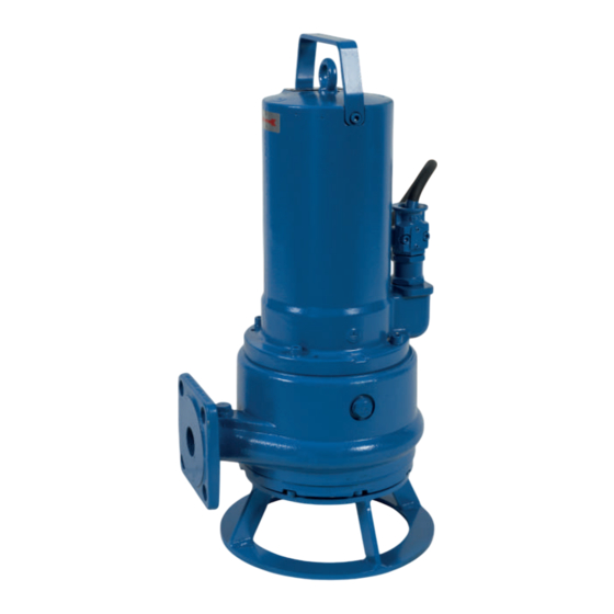
Sanipump ZFS 71
Pompe submersible pour évacuation des eaux usées
FR
Submersible waste water pump
EN
Abwasser-Tauchpumpe
DE
Pompa sommersa per acque reflue
IT
Afvalwater-dompelpomp
NL
Bomba sumergible para aguas residuales
ES
Bomba submersível para águas residuais
PT
Operating/installation manual
•
Bedienungs-/Installationsanleitung
•
Manuale per l'uso e l'installazione
•
Gebruikers-/installatiehandleiding
•
•
•
1
Notice de service/montage
•
Manual de instalación e uso
Manual de instalação/utilização
Werbung
Kapitel
Inhaltsverzeichnis
Fehlerbehebung

Verwandte Anleitungen für SFA Sanipump ZFS 71


Inhaltszusammenfassung für SFA Sanipump ZFS 71
- Seite 1 903O 09.21 Sanipump ZFS 71 Pompe submersible pour évacuation des eaux usées Notice de service/montage • Submersible waste water pump Operating/installation manual • Abwasser-Tauchpumpe Bedienungs-/Installationsanleitung • Pompa sommersa per acque reflue Manuale per l’uso e l’installazione • Afvalwater-dompelpomp Gebruikers-/installatiehandleiding • Bomba sumergible para aguas residuales Manual de instalación e uso •...
- Seite 3 Français ........6 English .......... 14 Deutsch ......... 22 Italiano ......... 30 Nederlands ........38 Español ......... 46 Português ........54...
-
Seite 4: Raccordement Électrique
Connect the device to the mains according to the AVERTISSEMENT country’s standards. Cet appareil peut être utilisé par des enfants If the power cord is damaged, to prevent possible âgés d’au moins 8 ans et par des personnes danger, it must be replaced by the manufacturer, ayant des capacités physiques sensorielles ou customer service team or a similarly qualified mentales réduites ou dénuées d’expérience ou... -
Seite 5: Ligação Elétrica
(30 mA). I dispositivi senza prese devono realizadas por crianças sem supervisão. essere collegati ad un interruttore principale di LIGAÇÃO ELÉTRICA alimentazione che garantisca la disconnessione A instalação eléctrica deve ser realizada por di tutti i poli (distanza di separazione dei contatti: um profissional qualificado em engenharia almeno 3 mm). -
Seite 6: Inhaltsverzeichnis
Annexe C : Schéma en coupe et liste des pièces de rechange ........13 Notice d'installation et de service Sanipump ZFS 71. Notice d'origine. Tous droits réservés. Les contenus de ce document ne doivent pas être divulgués, reproduits, modifiés ou communiqués à des tiers sauf autorisation écrite du fabricant. -
Seite 7: Sécurité
1. SÉCURITÉ décrits dans la présente documentation. • La pompe ne doit jamais fonctionner sans fluide 1.1 IDENTIFICATION DES AVERTISSEMENTS pompé. Signification • Ne jamais dépasser les limites d’utilisation DANGER Ce terme définit un danger définies dans la documentation. à risques élevés pouvant •... -
Seite 8: Risques En Cas De Non-Respect Des Consignes De Sécurité
Utiliser des moyens de transport adéquats. effectués par du personnel qualifié et autorisé, • Les pompes Sanipump ZFS 71 doivent toujours être soulevées et/ qui s'est informé par une étude suffisante du ou transportées par les anneaux ou la poignée de transport prévus à... -
Seite 9: Courbes De Performance
GG 20 3.6 MOTEUR Arbre moteur 1.4021 Les pompes Sanipump ZFS 71 II 2G EEx d IIB T3 sont équipées d’un Carter de la pompe GG 20 moteur asynchrone à courant alternatif. Dans chacun des trois bobi- Bride de support GG 20 nages du moteur, des sondes de température (bi-métal) sont inté-... -
Seite 10: Mise En Place Et Raccordement Hydraulique
- Circuit de régulation : TB1 et TB2 doivent être raccordés dans un Sanipump ZFS 71.1 S le branchement est réalisé comme suit : boîtier de commande tels que : si ces capteurs thermiques s’en- clenchent, la pompe est arrêtée jusqu’à ce que la température re- RÉSEAU... -
Seite 11: Mise En Place Pour Installation Dans Une Cuve
Contrôler/ 4.3 CORRECTEUR DE NIVEAU commutateur du moteur informer le Les pompes Sanipump ZFS 71 doivent être commandées par un sys- défectueux service SAV tème de contrôle de niveau de telle sorte qu'une baisse du niveau d'eau en-dessous du niveau minimum admissible (bord inférieur du Défaillance du moteur... -
Seite 12: Annexe A : Exemples De Montage
Annexe A : Exemples de montage Coude de raccordement 90° Attache du rail Rail de guidage 5/4'' Vanne de verrouillage Clapet anti-retour Chaîne de relevage avec manille Système d’accouplement Couronne d’appui Coude de raccordement 90° Annexe B : Valeurs de réglage de la hauteur («brèche») de coupe et de l’hydraulique de pompe... -
Seite 13: Annexe C : Schéma En Coupe Et Liste Des Pièces De Rechange
Annexe C : Schéma en coupe et liste des pièces de rechange Réf schéma Réf. art. Désignation Quantité 17369 Moteur complet SANIPUMP® ZFS 71.1 S 230 V 17368 Moteur complet SANIPUMP® ZFS 71.1 T et ZFS 71.2 T 400 V 17370 Moteur complet SANIPUMP®... - Seite 14 Appendix C: Sectional drawing and list of spare parts .............21 Sanipump ZFS 71 Installation and Maintenance Manual - Original operating instructions All rights reserved. The contents of this document must not be reproduced, modified or disclosed to third parties except upon written consent...
-
Seite 15: Safety
1. SAFETY and the surveillance of the personnel have to be regulated precisely by the operator. If the personnel 1.1 IDENTIFICATION OF WARNINGS do not possess the necessary knowledge, they Meaning have to be trained and instructed. DANGER This term defines a high risk of Furthermore the operator has to make sure that danger, which can lead to death the personnel have completely understood the... -
Seite 16: Dangers From Non-Observance Of The Safety Instructions
Sanipump ZFS 71 are used for the drainage of sewage and wastewa- • Operational safety of the delivered machine is ter tanks, excrement collection pits, sewage plants and the like in only guaranteed when it is used appropriately explosion-prone areas. -
Seite 17: Curve
(example of installation in annex). DANGER 3.6 MOTOR The pumps Sanipump ZFS 71 II 2G EEx d IIB T3 are equipped with The switching device has to be installed outside an AC asynchronous induction motor or a three-phase asynchronous the explosion-prone area! motor. -
Seite 18: Fitting And Hydraulic Connection
Motor protection 4.3 LEVEL CONTROL SYSTEM The pumps Sanipump ZFS 71 have to be controlled by means of a le- vel control in such a way, that a decline of the water level beneath the Thermal winding protection minimum allowable level (bottom line of motor housing) is avoided Control circuit Clipping circuit at all costs. -
Seite 19: Maintenance And Repair
DISCONNECT THE PUMP BEFORE ANY INTERVEN- Sanipump ZFS 71 conform to Low Voltage, EMC and Machinery di- TION ! rectives. After an operation time of six to twelve months, the oil storage inside the seal carrier always has to be controlled as follows: 9. -
Seite 20: Appendix A: Installation Suggestions
Appendix A: Installation suggestions Flange elbow 90° Rail fastener Guide rail 5/4'' Wedge-type flat slide valve Non return valve Lowering chain with clevis Coupling system Supporting ring Flange elbow 90° Appendix B: Adjustment values for cutting gap and pump hydraulics... -
Seite 21: Appendix C: Sectional Drawing And List Of Spare Parts
Appendix C: Sectional drawing and list of spare parts Ref. drawing Art. Nr. Designation Quantity 17369 Motor complete SANIPUMP® ZFS 71.1 S 230 V 17368 Motor complete SANIPUMP® ZFS 71.1 T and ZFS 71.2 T 400 V 17370 Motor complete SANIPUMP® ZFS 71.3 T and ZFS 71.4 T 400 V 17356 GLRD LD1/25-G38 motor side 11679... - Seite 22 Anhang B: Einstellwerte für Schneidspalt und Pumpenhydraulik ........28 Anhang C: Schnittzeichnung und Ersatzteilliste ..............29 Installations-, Wartungs- und Montageanleitung Sanipump ZFS 71 - Originalbetriebsanleitung - Alle Rechte vorbehalten Die Inhalte dieses Dokuments dürfen nicht ohne schriftliche Genehmigung des Herstellers verbreitet, reproduziert, geändert oder an Dritte wei-...
-
Seite 23: Sicherheithinweis
1. SICHERHEITHINWEIS Flüssigkeit betrieben werden. • Überschreiten Sie niemals die in dieser Anleitung 1.1 KENNZEICHNUNG VON WARNUNGEN festgelegten Nutzungsbeschränkungen. Bedeutung 1.4 PERSONALQUALIFIKATION UND SCHULUNG GEFAHR Dieser Begriff definiert eine Das Personal für Bedienung, Wartung, Inspektion Gefahr mit erhöhtem Risiko, Montage muss entsprechende dass zum Tod oder schweren... -
Seite 24: Gefahren Bei Nichtbeachtung Der Sicherheitshinweise
Benutzen Sie geeignete Transporthilfsmittel. S1 - Dauerbetrieb (vollständig überflutet) Rel. Einschaltdauer S3 - 40 % (ausgetaucht) • Die Pumpen Sanipump ZFS 71 soll grundsätzlich an der hierfür vorgesehenen Öse an der Oberseite oder am Handgriff angehoben Mindest- Unterkante Motorgehäuse und/oder transportiert werden. -
Seite 25: Kennlinien
• Bei Drehstromanschluss ist die externe Absicherung mit Siche- 3.6 MOTOREN rungsautomaten der Charakteristik K generell 3-polig mechanisch Die Pumpen Sanipump ZFS 71 II 2G EEx d IIB T3 sind mit einem verriegelt auszuführen. Damit ist eine komplette Netztrennung si- Wechsel- bzw. Drehstrom-Asynchronmotor ausgestattet. -
Seite 26: Installation Und Hydraulischer Anschluss
Eine weitere elektrische Installation ist nicht notwendig. Bei Bedarf kann das Motorgehäuse an der dafür vorgesehenen externen Er- dungsklemme zusätzlich geerdet werden. Wird ein Schaltgerät an die Pumpe Sanipump ZFS 71.1 S angeschlos- 400 V sen, so erfolgt der Anschluss wie folgt:... -
Seite 27: Niveauregulierung
überprüfen 4.3 NIVEAUREGULIERUNG fehlerhafter An- Anschluss korrigieren Die Pumpen Sanipump ZFS 71 müssen so über eine Niveauregulierung schluss gesteuert werden, dass ein Absinken des Wasserstandes unter den mi- defektes Strom- Austausch (Kunden- nimal zulässigen Pegel (Unterkante Motorgehäuse) unbedingt vermie-... -
Seite 28: Anhang A: Einbaubeispiele
Anhang A: Einbaubeispiele Flanschkrümmer Rohrspanner Führungsrohr 5/4‘‘ Keilflachschieber Rückflußverhinderer Ablasskette mit Schäkel Kupplungssystem Bodenstützring Flanschkrümmer Anhang B: Einstellwerte für Schneidspalt und Pumpenhydraulik... -
Seite 29: Anhang C: Schnittzeichnung Und Ersatzteilliste
Anhang C: Schnittzeichnung und Ersatzteilliste Pos. Art. Nr. Bezeichnung Menge 17369 Motor komplett SANIPUMP® ZFS 71.1 S 230 V 17368 Motor komplett SANIPUMP® ZFS 71.1 T und ZFS 71.2 T 400 V 17370 Motor komplett SANIPUMP® ZFS 71.3 T und ZFS 71.4 T 400 V 17356 GLRD LD1/25-G38 Motorseitig 11679... - Seite 30 Allegato C: Disegno in sezione e lista ricambi ..............37 Note legali - Manuale per l'uso e l'installazione di Sanipump ZFS 71 Tutti i diritti riservati. I contenuti del presente documento non possono essere riprodotti, modificati o comunicati a terzi, se non previo consenso scritto da parte del fabbricante.
-
Seite 31: Sicurezza
1. SICUREZZA • Non superare mai i limiti d’utilizzo definiti nella documentazione. 1.1 IDENTIFICAZIONE DEGLI AVVISI Il funzionamento sicuro della pompa è garantito Significato solo se viene utilizzata in conformità con queste PERICOLO Questo termine definisce istruzioni. un pericolo derivante da 1.4 QUALIFICAZIONE E FORMAZIONE DEL rischi elevati che potrebbero PERSONALE... -
Seite 32: Rischi E Conseguenze Del Mancato Rispetto Delle Istruzioni Del Manuale Per L'uso
3.1 APPLICAZIONE o messi in funzione. Le pompe sommerse per acque reflue tipo Sanipump ZFS 71 vengo- • Prima della (ri)messa in servizio è necessario no utilizzate per il drenaggio di pozzi di raccolta delle acque reflue, pozzi di raccolta deiezioni, impianti di depurazione, ecc. -
Seite 33: Curve Di Prestazioni
(preferibilmente per uso trasportabile) o un dispositivo di zionamento” e “guasto”, relè Ex i - e galleggiante per la protezione accoppiamento (uso stazionario). contro il funzionamento a secco. 3.6 MOTORI Le pompe Sanipump ZFS 71 II 2G EEx d IIB T3 sono dotate di motore... -
Seite 34: Impostazione E Collegamento Idraulico
Protezione Protezione termica motore Modello monofase dell'avvolgimento Se alla pompa Sanipump ZFS 71.1 S è collegato un dispositivo di Circuito Circuito di commutazione, il collegamento si esegue come segue: limitatore regolazione RETE Relè... -
Seite 35: Regolazione Del Livello
Sostituzione/ (solo per motore a corrente servizio clienti Le pompe Sanipump ZFS 71 devono essere comandate tramite un si- alternata) stema di controllo del livello in modo tale da evitare assolutamente un abbassamento del livello dell’acqua al di sotto del livello minimo con-... -
Seite 36: Allegato A: Esempi Di Installazione
Allegato A: Esempi di installazione Raccordo a gomito flangiato Morsetto per tubi Tubo di guida 5/4’’ Valvola di bloccaggio Valvola di non ritorno Catena di sollevamento con grillo Sistema di accoppiamento Anello di supporto a pavimento Raccordo a gomito flangiato Allegato B: Valori di regolazione per la fessura di taglio e l’impianto idraulico della pompa... -
Seite 37: Allegato C: Disegno In Sezione E Lista Ricambi
Allegato C: Disegno in sezione e lista ricambi N° articolo Designazione 1 N° disegno Quantità 17369 Motore completo SANIPUMP® ZFS 71.1 S 230 V 17368 Motore completo SANIPUMP® ZFS 71.1 T e ZFS 71.2 T 400 V 17370 Motore completo SANIPUMP® ZFS 71.3 T e ZFS 71.4 T 400 V 17356 GLRD LD1/25-G38 Lato motore 11679... - Seite 38 Bijlage B: Instelwaarden voor snijopening en pomphydrauliek ........44 Bijlage C: Doorsnedetekening en lijst met reserveonderdelen ........45 Installatie- en onderhoudsinstructies voor de Sanipump ZFS 71 - Originele handleiding - Alle rechten voorbehouden. De inhoud van dit document mag niet gepubliceerd, gereproduceerd, gewijzigd of aan derden doorgegeven worden zonder schriftelijke toe- stemming van de fabrikant.
-
Seite 39: Algemeen
(bv. koppeling) mag bij een werkende machine montage, het gebruik en het onderhoud van niet verwijderd worden. het Sanipump ZFS 71 pomp. Het opvolgen van • Lekkages (bv. van de asdichting) van gevaarlijke deze instructies garandeert een veilig gebruik en transportgoederen (bv. -
Seite 40: Gevaren Bij Niet Beachten Van De Veiligheidsinstructies
Gebruik geschikte transportmiddelen. studie van de gebruiksaanwijzing voldoende • De pompen Sanipump ZFS 71 moet in principe aan het hiervoor heeft geïnformeerd. voorziene oogje aan de bovenzijde of aan de handgreep opgeheven en/of vervoerd worden. In geen geval mag de pomp aan de toevoer- •... -
Seite 41: Prestatiecurve
Rel. inschakelduur ondergedompeld), S3 - 40 % (boven water) Minimum vloeistofniveau onderkant motorbehuizing 3.5 LEVERINGSOMVANG Alle pompen van de Sanipump ZFS 71 serie worden geleverd met Materialen een gratis kabeluiteinde (zonder stekker). Optie : Motorhuis GG 20 Schakelkasten voor pompen met explosiebeveiliging zijn verkrijg- Motoras 1.4021... -
Seite 42: Voorbereiding En Hydraulische Aansluiting
Springen deze Eenfasig model thermovoelers aan, dan wordt de pomp afgeschakeld, tot de tempe- Wordt een schakeltoestel aan de pomp Sanipump ZFS 71.1 S aange- ra-tuur terug gezakt is. Nu schakelt de pomp terug aan. sloten, dan gebeurt de aansluiting als volgt: - Begrenzerkring : TB2 en TB3 moeten in een schakeltoestel zo aan-... -
Seite 43: Opstelling Voor Schachtinbouw
(klantenservice) sen leggen. Waaier/snijmes Reinigen 4.3 NIVEAUREGELING geblokkeerd De pompen Sanipump ZFS 71 moeten zo via een niveauregeling ge- Geactiveerde Controleer, stuurd worden, dat een daling van het waterniveau tot onder het mi- motorbeveiliging informeer de nimumniveau (onderkant motorbehuizing) absoluut vermeden wordt. -
Seite 44: Bijlage A: Inbouwvoorbeelden
Bijlage A: Inbouwvoorbeelden Flensspruitstuk Buizenspanner Geleidebuis 5/4'' Penschuifafsluiter Terugstroombeveiliging Hijsketting met sluiting Koppelingssysteem Vloersteunring Flensspruitstuk Bijlage B: Instelwaarden voor snijopening en pomphydrauliek... -
Seite 45: Bijlage C: Doorsnedetekening En Lijst Met Reserveonderdelen
Bijlage C: Doorsnedetekening en lijst met reserveonderdelen Ref. Aanduiding 1 Art.nr. Hoeveelheid tekening 17369 Motor compleet SANIPUMP® ZFS 71.1 S 230 V 17368 Motor compleet SANIPUMP® ZFS 71.1 T en ZFS 71.2 T 400 V 17370 Motor compleet SANIPUMP® ZFS 71.3 T en ZFS 71.4 T 400 V 17356 GLRD LD1/25-G38 Motorzijde 11679... - Seite 46 Todos los derechos reservados. Los contenidos de este documento no deben divulgarse, reproducirse, modificarse ni comunicarse a terceros sin la autorización por escrito del fabricante. Este documento podrá estar sujeto a modificaciones sin aviso previo. SFA – 41 Bis Avenue Bosquet – 75007 PARÍS...
-
Seite 47: Seguridad
• La protección contra contactos de los las bombas Sanipump ZFS 71. El cumplimiento de componentes móviles (p. ej., acoplamiento) no estas instrucciones garantiza un funcionamiento debe ser retirada en caso de que la máquina se seguro y evitará... -
Seite 48: Indicaciones De Seguridad Durante Los Trabajos De Mantenimiento, Inspección E Instalación
• Las bombas Sanipump ZFS 71 deben elevarse y/o transportarse siempre del ojal que se encuentra en la parte superior o en el mango. • Los trabajos en la máquina sólo deben realizarse En ningún caso, la bomba debe elevarse del cable de alimentación. -
Seite 49: Curvas De Rendimientos
Altura máx. de bombeo Hmax (m) Temperatura máx. 3.5 ELEMENTES SUMINISTRADOS del fluido Tmax (°C) Todas las bombas de la serie Sanipump ZFS 71 se suministran con un Conexión de presión Brida DN50 extremo de cable suelto. Peso con cable (kg) Disponible como opción :... -
Seite 50: Colocación Y Conexión Hidráulica
Si se conecta un dispositivo de conmutación a la bomba que la temperatura vuelva a bajar. A continuación, la bomba se vol- Sanipump ZFS 71.1 S la conexión se realiza de la siguiente manera: verá a conectar. - Circuit limitador: TB2 y TB3 deben conectarse en un dispositivo de conmutación de modo que se garantice la siguiente función: Si... -
Seite 51: Instalación Para Montaje En Arqueta
4.3 REGULACIÓN DE NIVEL otro daño) Las bombas Sanipump ZFS 71 deben controlarse por medio de una re- gulación de nivel de modo que se evite una caída del nivel de agua Error en el control/ Comprobación, por debajo del nivel mínimo permitido (borde inferior de la carcasa del... -
Seite 52: Anexo A: Ejemplos De Instalación
Anexo A: Ejemplos de instalación Codo 90° con brida Soporte de tubo Tubo guía 5/4'' Válvula de bloqueo Válvula de retención Cadena de elevación con grillete Sistema de acoplamiento Conjunto de soporte Codo 90° con brida Anexo B: Valores de ajuste para ranura de corte y sistema hidráulico de las bombas... -
Seite 53: Anexo C: Dibujo Seccional Y Listado De Piezas De Recambio De La Bomba
Anexo C: Dibujo seccional y listado de piezas de recambio de la bomba Ref. N° art. Denominación 1 Cantidad dibujo 17369 Motor completo SANIPUMP® ZFS 71.1 S 230 V 17368 Motor completo SANIPUMP® ZFS 71.1 T y ZFS 71.2 T 400 V 17370 Motor completo SANIPUMP®... - Seite 54 Anexo C: Desenho seccional e lista de peças sobressalentes .........61 Instruções de instalação e funcionamento para Sanipump ZFS 71. Instruções de funcionamento originais. Todos os direitos reservados. O conteúdo deste documento não pode ser divulgado, reproduzido, modificado ou comunicado a terceiros sem a autorização escrita do fabricante.
-
Seite 55: Segurança
Os regulamentos legais devem da bomba Sanipump ZFS 71. O respeito por estas ser respeitados. instruções garante um funcionamento seguro e • Os perigos da energia elétrica devem ser evita lesões e danos materiais. -
Seite 56: Consequências E Riscos Em Caso De Desrespeito Do Manual De Serviço
Peso com cabo (kg) Utilize os meios de transporte adequados. S1- funcionamento contínuo (completa- Ciclo de • As bombas Sanipump ZFS 71 devem ser sempre levantadas e/ou mente inundado), funcionamento real transportadas no olhal previsto para tal na parte superior ou na pega. -
Seite 57: Curva
60 µF, intertravamento de partida para circuito do limitador, lâm- As bombas Sanipump ZFS 71 II 2G EEx d IIB T3 estão equipados com padas de sinalização “operação” e “falha”, relé Ex i - e um flutuador um motor assíncrono de corrente alternada ou trifásico. -
Seite 58: Montagem E Ligação Hidráulica
à terra previsto para o efeito. controlo Relé motor Modelo monofásico: aparelho comutação estiver ligado à bomba Sanipump ZFS 71.1 S a ligação é feita da seguinte forma: REDE 1~ 230 V/50 Hz Fusível 400 V 50 Hz Verde/Amarelo PE Condutor de proteção Disjuntor Protecção térmica Ligação da proteção térmica do enrolamento:... -
Seite 59: Regulação Do Nível
Corrigir a ligação 4.3 REGULAÇÃO DO NÍVEL Cabo de alimentação Troca (Serviço ao As bombas Sanipump ZFS 71 devem ser comandadas através de um defeituoso Cliente) controlo de nível, de modo a evitar absolutamente uma descida do nível de água abaixo do nível mínimo admissível (borda inferior da carcaça Condensador avariado/ Troca (Serviço ao... -
Seite 60: Anexo A: Exemplos De Montagem
Anexo A: Exemplos de montagem Cotovelo de flange Tensor de tubo Tubo condutor 5/4'' Válvula de cunha Válvula de retenção Corrente de elevação com grilheta Sistema de acoplamento Anel de suporte de piso Cotovelo de flange Anexo B: Valores de ajuste da folga de corte e do sistema hidráulico da bomba... -
Seite 61: Anexo C: Desenho Seccional E Lista De Peças Sobressalentes
Anexo C: Desenho seccional e lista de peças sobressalentes Ref. Artigo n° Designação 1 Quantidade desenho 17369 Motor completo SANIPUMP® ZFS 71.1 S 230 V 17368 Motor completo SANIPUMP® ZFS 71.1 T e ZFS 71.2 T 400 V 17370 Motor completo SANIPUMP® ZFS 71.3 T e ZFS 71.4 T 400 V 17356 GLRD LD1/25-G38 do lado do motor 11679... - Seite 64 +86(0)21 6218 8969 +86(0)21 6218 8970 Portugal +35 21 911 27 85 Brazil (11) 3052-2292 Suisse Schweiz Svizzera +41 (0)32 631 04 74 +41 (0)32 631 04 75 New Zealand 0800107264 Benelux +31 475 487100 +31 475 486515 Service information : www.sfa.biz...