Inhaltsverzeichnis
Werbung
Quicklinks
19438-6NL-07
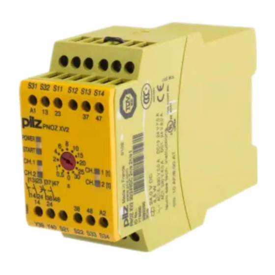
PNOZ XV2
Sicherheitsbestimmungen
• Das Gerät darf nur von Personen installiert
und in Betrieb genommen werden, die mit
dieser Betriebsanleitung und den geltenden
Vorschriften über Arbeitssicherheit und
Unfallverhütung vertraut sind. Beachten Sie
die VDE- sowie die örtlichen Vorschriften,
insbesondere hinsichtlich Schutzmaßnahmen.
• Beim Transport, der Lagerung und im Betrieb
die Bedingungen nach EN 60068-2-6
einhalten (s. technische Daten).
• Durch Öffnen des Gehäuses oder eigen-
mächtige Umbauten erlischt jegliche Ge-
währleistung.
• Montieren Sie das Gerät in einen Schalt-
schrank; Staub und Feuchtigkeit können sonst
zu Beeinträchtigungen der Funktionen führen.
• Sorgen Sie an allen Ausgangskontakten bei
kapazitiven und induktiven Lasten für eine
ausreichende Schutzbeschaltung.
• Hinweis für Überspannungskategorie III:
Wenn am Gerät höhere Spannungen als
Kleinspannung (>50 V AC oder
>120 V DC) anliegen, müssen angeschlosse-
ne Bedienelemente und Sensoren eine
Bemessungsisolationsspannung von mind.
250 V aufweisen.
Bestimmungsgemäße Verwendung
Das Sicherheitsschaltgerät dient dem
sicherheitsgerichteten Unterbrechen eines
Sicherheitsstromkreises. Das Sicherheits-
schaltgerät erfüllt Forderungen der
EN 60947-5-1, EN 60204-1 und
VDE 0113-1 und darf eingesetzt werden in
Anwendungen mit
• Not-Halt-Tastern
• Schutztüren
Gerätebeschreibung
Das Sicherheitsschaltgerät ist in einem
P-97-Gehäuse untergebracht. Es steht eine
Ausführung für den Betrieb mit 24 V
Gleichspannung zur Verfügung.
Merkmale:
• Relaisausgänge, unverzögert:
2 Sicherheitskontakte (S), zwangsgeführt
• Relaisausgänge, rückfallverzögert:
2 Sicherheitskontakte (S), zwangsgeführt,
mit einstellbarer oder fester Rückfallver-
zögerung (geräteabhängig)
• Statusanzeigen für Versorgungsspannung,
Schaltzustand aller Ausgangsrelais und
Startkreis
• Anschluss für Not-Halt-Taster, Sicher-
heitsendschalter oder Schutztürschalter
und für externen Starttaster
• redundante Ausgangsschaltung
• ein- oder zweikanaliger Betrieb
• Rückführkreis zur Überwachung externer
Schütze
Das Schaltgerät erfüllt folgende Sicherheits-
anforderungen:
• Die Sicherheitseinrichtung bleibt auch in
folgenden Fällen wirksam:
- Spannungsausfall
- Ausfall eines Bauteils
- Spulendefekt
- Leiterbruch
- Erdschluss
Safety Regulations
• The unit may only be installed and
operated by personnel who are familiar
with both these instructions and the current
regulations for safety at work and accident
prevention. Follow VDE and local
regulations especially as regards
preventative measures.
• Transport, storage and operating con-
ditions should all conform to EN 60068-
2-6.
• Any guarantee is void following opening of
the housing or unauthorised modifications.
• The unit should be panel mounted,
otherwise dampness or dust could lead to
function impairment.
• Adequate protection must be provided on
all output contacts especially with
capacitive and inductive loads.
• Note for overvoltage category III:
If voltages higher than low voltage
(>50 VAC or >120 VDC) are present on
the unit, connected control elements and
sensors must have a rated insulation
voltage of at least 250 V.
Authorised Applications
The safety relay provides a safety-related
interruption of a safety circuit. The safety
relay meets the requirements of EN 60947-5-
1, EN 60204-1 and VDE 0113-1 and may be
used in applications with
• E-STOP pushbuttons
• Safety gates
Description
The Safety Relay is enclosed in a P-97
housing. The version available is for
24 V DC operation only.
Features:
• Relay Outputs, instantaneous
2 safety contacts (n/o), positive-guided
• Relay outputs, delay-on de-energised:
2 safety contacts (n/o), positive-guided
with adjustable or fixed delay-on de-
energisation (dependent on unit)
• LED for Operating Voltage, LED's for
switching positions of all output relays and
reset circuit
• Connection for Safety limit switches,
Emergency stop buttons or safety gate
switches and for external reset buttons
• Output circuit is redundant
• Single or two channel operation
• Feedback control loop for monitoring
external contactors/relays
The relay complies with the following safety
requirements:
• The Emergency Stop Relay prevents
machine operation in the following cases:
- Power supply failure
- Component failure
- Coil defect in a relay
- Cable break
- Earth fault
- 1 -
Conseils préliminaires
• La mise en oeuvre de l'appareil doit être
effectuée par une personne spécialisée en
installations électriques, en tenant compte
des prescriptions des différentes normes
applicables (NF, EN, VDE...) notamment
au niveau des risques encourus en cas de
défaillance de l'équipement électrique.
• Respecter les exigences de la norme
EN 60068-2-6 lors du transport, du
stockage et de l'utilisation de l'appareil.
• L'ouverture de l'appareil ou sa modification
annule automatiquement la garantie.
• L'appareil doit être monté dans une ar-
moire; l'humidité et la poussière pouvant
entraîner des aléas de fonctionnement.
• Vérifiez que le pouvoir de coupure des
contacts de sortie est suffisant en cas de
circuits capacitifs ou inductifs.
• Remarque relative à la catégorie de
surtensions III :
Si l'appareil est alimenté avec des tensions
supérieures à la basse tension (>50 V AC
ou >120 V DC), les éléments de commande
et les capteurs raccordés doivent supporter
une tension d'isolement assignée d'au
moins 250 V.
Domaines d'utilisation
Le bloc logique de sécurité sert à interrompre
en toute sécurité un circuit de sécurité. Le
bloc logique de sécurité satisfait aux
exigences des normes EN 60947-5-1,
EN 60204-1 et VDE 0113-1 et peut être
utilisé dans des applications avec des:
• poussoirs d'arrêt d'urgence
• protecteurs mobiles
Description de l'appareil
Inséré dans un boîtier P-97, le bloc logique
de sécurité PNOZ XV2 est disponible
uniquement en 24 V DC
Caractéristiques :
• Contacts de sortie instantanés :
2 contacts à fermeture de sécurité (F).
• Contacts de sortie temporisés :
2 contacts à fermeture de sécurité (F),
temporisés à la retombée avec tempori-
sation réglable ou fixe (suivant appareil)
• LED d'indication présence tension, LEDs
de visualisation des relais internes et du
circuit de réarmement
• Bornes de raccordement pour poussoirs
AU, fins de course de sécurité ou
interrupteurs de position et poussoir de
validation externe.
• Sorties redondantes.
• Commande par un ou deux canaux.
• Boucle de retour pour l'auto-contrôle de
contacteurs externes.
Le relais répond aux exigences suivantes :
• La sécurité est garantie, même dans les
cas suivants :
- Défaillance tension
- Défaillance d'un composant
- Défaillance bobine
- Défaut soudure
- Défaut de masse
Werbung
Inhaltsverzeichnis

Verwandte Anleitungen für Pilz 19438-6NL-07


Inhaltszusammenfassung für Pilz 19438-6NL-07
- Seite 1 19438-6NL-07 PNOZ XV2 Sicherheitsbestimmungen Safety Regulations Conseils préliminaires • Das Gerät darf nur von Personen installiert • The unit may only be installed and • La mise en oeuvre de l’appareil doit être und in Betrieb genommen werden, die mit operated by personnel who are familiar effectuée par une personne spécialisée en...
-
Seite 2: Funktionsbeschreibung
• Bei jedem Ein-Aus-Zyklus Überprüfung, ob • Vérification à chaque mise en route du bon • The correct opening and closing of the die Ausgangsrelais des Sicherheitsgerätes Safety Gate limit switches and the safety fonctionnement des relais internes richtig öffnen und schließen function output relays is tested automatically in each on-off cycle Funktionsbeschreibung... -
Seite 3: Mise En Oeuvre
• As the function for detecting shorts across /km = Leitungswiderstand/km • La fonction de détection de court-circuit est the inputs is not failsafe, it is tested by Pilz • Da die Funktion Querschlusserkennung testé par Pilz lors du contrôle final. Un test during the final control check. -
Seite 4: Anwendung
Ablauf: To operate: Mise en oeuvre : • Versorgungsspannung an Klemmen A1 • Supply operating voltage: • Tension d’alimentation: und A2 anlegen. Connect the operating voltage to terminals amener la tension d’alimentation sur A1 et • Startkreis: A1 and A2 - Automatischer Start: S13-S14 brücken. - Seite 5 S11 S31 S11 S31 Fig. 3: Eingangskreis einkanalig, überwach- Fig. 4: Eingangskreis zweikanalig, überwach- Fig. 2: Eingangskreis einkanalig, automat. ter Start/Single-channel input circuit, ter Start/Two-channel input circuit, monitored Start/Single-channel input circuit, automatic monitored reset/Commande par 1 canal, reset/Commande par 2 canaux, surveillance reset/Commande par 1 canal, validation surveillance du poussoir de validation du poussoir de validation...
-
Seite 6: Fehler - Störungen
Fehler - Störungen Faults Erreurs - Défaillances • Erdschluss • Earth fault • Défaut de masse Eine elektronische Sicherung bewirkt das An electronic fuse causes the output Un fusible électronique entraîne l’ouverture Öffnen der Ausgangskontakte. Nach contacts to open. Once the cause of the des contacts de sortie. - Seite 7 SIL nach IEC 61511 SIL in accordance with IEC 61511 SIL selon IEC 61511 unverzögert instantaneous instantés SIL 3 verzögert <30 s delayed<30 s temporisés à retombée <30 s SIL 3 verzögert ≥30 s delayed ≥30 s temporisés à retombée ≥30 s SIL 2 PFD nach IEC 61511 PFD in accordance with IEC 61511...
- Seite 8 ACHTUNG! CAUTION! ATTENTION! Beachten Sie unbedingt die Lebensdauer- It is essential to consider the relay’s service Veuillez absolument tenir compte des courbes kurve der Relais. Die sicherheitstechnischen life graphs. The relay outputs’ safety-related de durée de vie des relais. Les caractéristiques Kennzahlen der Relaisausgänge gelten nur, characteristic data is only valid if the values de sécurité...
- Seite 9 Lebensdauerkurve Service life graph Courbe de durée de vie Die Lebensdauerkurven geben an, ab The service life graphs indicate the number Les courbes de durée de vie indiquent à welcher Schaltspielzahl mit verschleiß- of cycles from which failures due to wear partir de quel nombre de manoeuvres il faut bedingten Ausfällen gerechnet werden muss.
-
Seite 10: Abmessungen In Mm /Dimensions In Mm /Dimensions En Mm
Die vollständige EG-Konformitätserklärung The complete EC Declaration of Conformity Vous trouverez la déclaration de conformité finden Sie im Internet unter www.pilz.com is available on the Internet at www.pilz.com CE complète sur notre site internet Bevollmächtigter: Norbert Fröhlich, Authorised representative: Norbert Fröhlich, www.pilz.com... - Seite 11 19438-6NL-07 PNOZ XV2 Normas de seguridad Norme di sicurezza Veiligheidsvoorschriften • El dispositivo debe ser instalado y puesto en • L’apparecchio deve essere installato e • Het apparaat mag uitsluitend worden funcionamiento solo por personas, que tengan messo in funzione solo da persone a geïnstalleerd en in bedrijf genomen door...
-
Seite 12: Características Funcionales
El dispositivo cumple los siguientes requisi- L’apparecchio elettrico è conforme ai Het relais voldoet aan de volgende tos de seguridad: seguenti requisiti di sicurezza: veiligheidseisen: • El dispositivo de seguridad permanece • La funzione di sicurezza è garantita • De veiligheidsvoorziening blijft ook in de también activo en los siguientes casos: anche in caso di: volgende gevallen werken:... -
Seite 13: Puesta En Funcionamiento
• Poiché la funzione di rilevamento corto- door Pilz tijdens de eindcontrole getest. fallo, es proba-da por Pilz en el control circuito non è protetta dagli errori, essa Een controle na de installatie van het ap- final. - Seite 14 • A la hora de conectar interruptores de • Durante il collegamento di sensori di • Zorg er voor, dat bij het aansluiten van proximidad magnetosensibles basados prossimità magnetici con contatti Reed magnetische, op basis van Reed- en contactos Reed, prestar atención a evitare il sovraccarico del picco contacten gebaseerde que el pico máx.
- Seite 15 S11 S31 S11 S31 Fig. 2: Circuito de entrada monocanal, Fig. 3: Circuito de entrada monocanal, Fig. 4: Circuito de entrada bicanal, rearme automát. rearme/Circuito di entrata rearme supervisado/Circuito di entrata supervisado/Circuito di entrata bicanale, monocanale, start automat./Eenkanalig monocanale, start controllato/Eenkanalig start controllato/Tweekanalig ingangscircuit, ingangscircuit, automatische start ingangscircuit, bewaakte start...
-
Seite 16: Datos Técnicos
• No está encendido el LED “Power”: Falta la • Il LED „Power“ non si accende: • LED „Power“ licht niet op: kortsluiting of tensión de alimentación o existe un cortocircuito o tensione di alimentazione geen voedingsspanning. cortocircuito interno. interrotta. •... - Seite 17 Tiempos Tempi Tijden Retardo a la conexión Ritardo d’inserzione Inschakelvertraging rearme automático Start automatico Automatische start typ. 350 ms, max. 650 ms rearme automático tras conexión Start automatico dopo attivazione Automatische start na de red dell'alimentazione di rete netinschakeling typ. 385 ms, max. 700 ms rearme supervisado Start controllato Bewaakte start...
- Seite 18 ATENCIÓN! ATTENZIONE! LET OP! Respetar al pie de la letra las curvas de Rispettare le curve di durata dei relè. I dati Let altijd op de levensduurkrommen van de vida útil de los relés. Las cifras tecnici di sicurezza delle uscite a relè sono relais.
- Seite 19 Curva de vida útil Curva del ciclo di vita Levensduurkrommen Las curvas de vida útil indican el número de Le curve di durata indicano da quale ciclo di De levensduurkrommen geven aan, vanaf ciclos a partir del cual pueden producirse commutazione è...
-
Seite 20: Declaración Ce De Conformidad
CE è disponibile in Internet Gevolmachtige: Norbert Fröhlich, Internet www.pilz.com all’indirizzo www.pilz.com Pilz GmbH & Co. KG, Felix-Wankel-Str. 2, Apoderado: Norbert Fröhlich, Mandatario: Norbert Fröhlich, 73760 Ostfildern, Duitsland Pilz GmbH & Co. KG, Felix-Wankel-Str. 2, Pilz GmbH &...