Herunterladen Inhalt Inhalt Diese Seite drucken

Werbung

Verfügbare Sprachen

Verfügbare Sprachen

Istruzioni per installazione, uso e manutenzione
Montage und Bedienungsanleitung
Manuel d'entretien
Installation, use and maintenance instructions
Bruciatore di gasolio
I
Öl-Gebläsebrenner
D
Brûleur fioul
F
Oil burner
GB
Funzionamento bistadio
Zweistufiger Betrieb
Fonctionnement à 2 allures
Two stage operation
CODICE
CODE
3739451
All manuals and user guides at all-guides.com
MODELLO - MODELL
MODELE - MODEL
RG3D
TIPO - TYP
TYPE
394 T1
2902332 (4)

Werbung

Inhaltsverzeichnis
loading

Inhaltszusammenfassung für Riello Burners RG3D 394 T1

  • Seite 1 All manuals and user guides at all-guides.com Istruzioni per installazione, uso e manutenzione Montage und Bedienungsanleitung Manuel d’entretien Installation, use and maintenance instructions Bruciatore di gasolio Öl-Gebläsebrenner Brûleur fioul Oil burner Funzionamento bistadio Zweistufiger Betrieb Fonctionnement à 2 allures Two stage operation CODICE MODELLO - MODELL TIPO - TYP...
  • Seite 2 All manuals and user guides at all-guides.com...
  • Seite 3: Descrizione Del Bruciatore

    All manuals and user guides at all-guides.com INDICE DESCRIZIONE DEL BRUCIATORE ..1 FUNZIONAMENTO ....1.1 Materiale a corredo ....1 4.1 Regolazione della combustione .
  • Seite 4: Dati Tecnici

    All manuals and user guides at all-guides.com DATI TECNICI 2.1 DATI TECNICI TIPO 394 T1 ÷ ÷ Portata - Potenza termica 5,5 / 7 15 kg/h – 65 / 83 178 kW ÷ Combustibile Gasolio, viscosità 4 6 mm /s a 20°C ±...
  • Seite 5: Fissaggio Alla Caldaia

    All manuals and user guides at all-guides.com INSTALLAZIONE 3.1 FISSAGGIO ALLA CALDAIA D5012 Fig. 2 Fig. 4 S7071 D5025 Fig. 3 Fig. 5 Inserire sulla flangia (1) la vite e i due dadi, (vedi fig. 3). Allargare, se necessario, i fori dello schermo isolante (4), (vedi fig. 4). Fissare alla portina della caldaia (3) la flangia (1) mediante le viti (5) e (se necessario) i dadi (2) interponendo lo schermo isolante (4), (vedi fig.
  • Seite 6: Impianti Idraulici

    All manuals and user guides at all-guides.com 3.3 IMPIANTI IDRAULICI ATTENZIONE Accertarsi, prima di mettere in funzione il bruciatore, che il tubo di ritorno del combustibile non abbia occlusioni. Una eccessiva contropressione provocherebbe la rottura dell’organo di tenuta della pompa. La pompa è...
  • Seite 7: Collegamenti Elettrici

    All manuals and user guides at all-guides.com 3.4 COLLEGAMENTI ELETTRICI NOTE: ATTENZIONE – Sezione dei conduttori 1,5 mm NON SCAMBIARE IL – I collegamenti elettrici eseguiti dall’installatore devono rispettare NEUTRO CON LA FASE le norme vigenti nel paese. (Vedi pag. 4). Collegare il dispositivo automatico di intercettazio- 230V 50Hz ne (230V - 0,5A max.) ai morsetti N - T2 della spina 7 poli.
  • Seite 8: Regolazione Della Combustione

    All manuals and user guides at all-guides.com FUNZIONAMENTO 4.1 REGOLAZIONE DELLA COMBUSTIONE In conformità con la Direttiva Rendimento 92/42/CEE, l’applicazione del bruciatore alla caldaia, la regolazione e il collaudo, devono essere eseguiti nell’osservanza del manuale d’istruzione della caldaia stessa, compreso il controllo della concentrazione di CO e CO nei fumi, della loro temperatura e di quella media dell’acqua della caldaia.
  • Seite 9: Regolazione Elettrodi

    All manuals and user guides at all-guides.com REGOLAZIONE TESTA (vedi fig. 12, pag. 6) Dipende dalla portata del bruciatore e si esegue ruotando in senso orario o antiorario la vite di regolazione (6) fino a che la tacca incisa sulla staffa di regolazione (7) coincide con il piano esterno del gruppo portaugello (1). –...
  • Seite 10: Programma Di Avviamento

    All manuals and user guides at all-guides.com 4.4 PROGRAMMA DI AVVIAMENTO Blocco per mancata Blocco per Normale accensione mancato spegnimento Termostato 1° stadio Termostato 2° stadio Motore Trasf. d’accensione Valvola 1° stadio Fiamma 1° stadio Valvola 2° stadio Fiamma 2° stadio Spia blocco Blocco per mancato ÷...
  • Seite 11 All manuals and user guides at all-guides.com ANOMALIE / RIMEDI Si elencano alcune cause e i possibili rimedi a una serie di anomalie che potrebbero verificarsi e portare ad un mancato o non regolare funzionamento del bruciatore. Un’anomalia, nel funzionamento nella maggior parte dei casi, porta alla accensione della segnalazione all’in- terno del pulsante di sblocco dell’apparecchiatura di comando e controllo (pos.
  • Seite 12: Norme Generali Di Sicurezza

    All manuals and user guides at all-guides.com NORME GENERALI DI SICUREZZA NORME GENERALI DI SICUREZZA PER L’INSTALLAZIONE, L’USO E LA MANUTENZIONE DEI BRUCIATORI DI COMBUSTIBILI LIQUIDI AD ARIA SOFFIATA A CUI DEVONO ATTENERSI L’INSTALLATORE, IL CONDUTTORE E L’UTENTE DELL’IMPIANTO TERMICO MANUALE D’ISTRUZIONE gato ad un efficace impianto di messa a terra, te all’interno della camera di combustione del gene-...
  • Seite 13: Beschreibung Des Brenners

    All manuals and user guides at all-guides.com INDEX BESCHREIBUNG DES BRENNERS ..1 BETRIEB ......1.1 Mitgeliefertes Zubehör .
  • Seite 14: Technische Merkmale

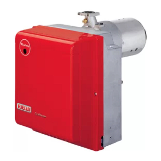
    All manuals and user guides at all-guides.com TECHNISCHE MERKMALE 2.1 TECHNISCHE DATEN 394 T1 ÷ ÷ Durchsatz - Feuerungswärmeleistung 5,5 / 7 15 kg/h – 65 / 83 178 kW ÷ Brennstoff Heizöl-EL, Viskosität 4 6 mm /s bei 20°C ±...
  • Seite 15: Brennstoffversorgung

    All manuals and user guides at all-guides.com INSTALLATION 3.1 BRENNERMONTAGE D5012 Abb. 2 Abb. 4 S7071 D5025 Abb. 3 Abb. 5 Die Schraube und die beiden Muttern am Flansch (1) montieren, (siehe Abb. 3). Falls erforderlich, die Bohrungen der Isolierdichtung (4) erweitern, (siehe Abb. 4). Mit den Schrauben (5) und (falls erforderlich) den Muttern (2) den Flansch (1) an der Kesseltür (3) mit Isolierdichtung (4) montieren, (siehe Abb 2).
  • Seite 16 All manuals and user guides at all-guides.com 3.3 ÖLVERSORGUNGSANLAGE WICHTIGER HINWEIS: Es muß sichergestellt werden, daß die Ölrücklauf-Leitung ohne Verengung und Verstopfung frei in den Tank zurückgeführt wird. Durch Druckerhöhung von mehr als 0,5 bar im Rücklauf wird die Ölpumpe undicht. Die Pumpe ist werksseitig für den Zweirohr-Betrieb eingerichtet.
  • Seite 17: Elektrisches Verdrahtungsschema

    All manuals and user guides at all-guides.com 3.4 ELEKTRISCHES VERDRAHTUNGSSCHEMA ANMERKUNGEN WICHTIGER HINWEIS – Leiterdurchmesser 1 mm NULLEITER NICHT MIT DER – Die vom Installateur ausgeführten elektrischen Verbindungen müssen PHASE VERWECHSELN den Lokalen Bestimmungen entsprechen. (Siehe Seite 4). Die automatische Absperrung (230V - 0,5 A max.) an den N –...
  • Seite 18: Betrieb

    All manuals and user guides at all-guides.com BETRIEB 4.1 EINSTELLUNG DER BRENNERLEISTUNG In Konformität mit der Wirkungsgradrichtlinie 92/42/EWG müssen die Anbringung des Brenners am Heizkessel, die Einstellung und die Inbetriebnahme unter Beachtung der Betriebsanleitung der Heizkessels ausgeführt werden, einschließlich Kontrolle der Konzentration von CO und CO in den Abgasen, ihrer Temperatur und der mittlenen Kesseltemperatur.
  • Seite 19: Elektrodeneinstellung

    All manuals and user guides at all-guides.com RBRENNERKOPFEINSTELLUNG (siehe Abb. 12, Seite 6) Sie ist vom Öldurchsatz abhängig und wird ausgeführt, indem man die Einstellschraube (6) im Uhrzeigersinn oder entgegen dem Uhrzeigersinn soweit dreht, bis die auf der Einstellspindel markierte Raste (7) mit der Kante am Düsenstock (1) übereinstimmt.
  • Seite 20: Wartung

    All manuals and user guides at all-guides.com 4.4 BETRIEBSABLAUF Störabschaltung wegen Störabschaltung Normal Nichtzündung wegen Nichtabschaltens 1. Stufe Thermostat 2. Stufe Thermostat Motor Zündtransformator 1. Stufe Ventil 1. Stufe Flamme 2. Stufe Ventil 2. Stufe Flamme Störlampe Störabschaltung wegen nicht ÷...
  • Seite 21: Störungen / Abhilfe

    All manuals and user guides at all-guides.com STÖRUNGEN / ABHILFE Nachfolgend finden Sie einige denkbare Ursachen und Abhilfemöglichkeiten für Störungen, die den Betrieb des Brenners beeinflussen oder einen nicht ordnungsgemäßen Betrieb des Brenners verursachen könn- ten. In den meisten Fällen führt eine Störung zum Aufleuchten der Kontrolleuchte in der Entstörtaste des Steuergeräts (4, Abb.
  • Seite 22: Inhaltsverzeichnis

    All manuals and user guides at all-guides.com SOMMAIRE DESCRIPTION DU BRULEUR..1 FONCTIONNEMENT....1.1 Matériel fourni ..... 1 4.1 Réglage de la combustion .
  • Seite 23: Donnees Techniques

    All manuals and user guides at all-guides.com DONNEES TECHNIQUES 2.1 DONNEES TECHNIQUES TYPE 394 T1 ÷ ÷ Débit - Puissance thermique 5,5 / 7 15 kg/h – 65 / 83 178 kW ÷ Combustible Fioul domestique, viscosité 4 6 mm /s à...
  • Seite 24: Installation

    All manuals and user guides at all-guides.com INSTALLATION 3.1 FIXATION A LA CHAUDIERE D5012 Fig. 2 Fig. 4 S7071 D5025 Fig. 3 Fig. 5 Insérer sur la bride (1) la vis et deux écrous, (voir fig. 3). Elargir, si nécessaire, les trous dans le joint isolant (4), (voir fig. 4). Fixer sur la plaque de la chaudière (3) la bride (1) par l’intermédiaire des vis (5) et (si nécessaire) des écrous (2) en interposant le joint isolant (4), (voir fig.
  • Seite 25: Installation Hydraulique

    All manuals and user guides at all-guides.com 3.3 INSTALLATION HYDRAULIQUE IMPORTANT: Avant de mettre en fonction le brûleur il faut s’assurer que le tube de retour du combustible ne soit pas obstrué. Une contre- pression excessive provoquerait la rupture de l’organe d’étan- chéité...
  • Seite 26: Raccordements Électriques

    All manuals and user guides at all-guides.com 3.4 RACCORDEMENTS ELECTRIQUES NOTES: ATTENTION – Section conducteurs 1 mm NE PAS INVERSER LE – Les branchements électriques exécutés par l’installateur NEUTRE AVEC LA PHASE doivent respecter le règlement en vigueur dans le Pays. (Voir page 4).
  • Seite 27: Fonctionnement

    All manuals and user guides at all-guides.com FONCTIONNEMENT 4.1 REGLAGE DE LA COMBUSTION Conformément à la Directive rendement 92/42/CEE, suivre les indications du manuel de la chaudière pour monter le brûleur, effectuer le réglage et l’essai, contrôler la concentration de CO et CO , dans les fumées, leur température et celle moyenne de l’eau de la chaudière.
  • Seite 28: Réglage Des Électrodes

    All manuals and user guides at all-guides.com REGLAGE TETE DE COMBUSTION (voir fig. 12, page 6) Est en fonction du débit du brûleur et on l’obtient en tournant la vis (6) jusqu’à ce que l’index sur la tige de régla- ge (7) concorde avec le plan (1) sur le groupe porte-gicleur.
  • Seite 29: Programme De Mise En Marche

    All manuals and user guides at all-guides.com 4.4 PROGRAMME DE MISE EN MARCHE Mise en sécurité due Mise en sécurité due Normal à non allumage à non extinction ère Therm. 1 allure ème Therm. 2 allure Moteur Transf. d’allumage ère Vanne 1 allure ère...
  • Seite 30: Pannes / Remedes

    All manuals and user guides at all-guides.com PANNES / REMEDES La liste ci-dessous donne un certain nombre de causes d’anomalies et leurs remèdes. Problèmes qui se traduisent par un fonctionnement anormal du brûleur. Un défaut, dans la grande majorité des cas, se traduit par l'allumage du signal sur le bouton de réar- mement manuel de la boîte de commande et de contrôle (4, fig.
  • Seite 31: Burner Description

    All manuals and user guides at all-guides.com INDEX BURNER DESCRIPTION ... . . 1 WORKING ..... . . 1.1 Burner equipment.
  • Seite 32: Technical Data

    All manuals and user guides at all-guides.com TECHNICAL DATA 2.1 TECHNICAL DATA TYPE 394 T1 Output - Thermal power 5.5 / 7 – 15 kg/h 65 / 83 – 178 kW Fuel Light oil, viscosity 4 – 6 mm /s at 20 °C ±...
  • Seite 33: Boiler Fixing

    All manuals and user guides at all-guides.com INSTALLATION 3.1 BOILER FIXING D5012 Fig. 2 Fig. 4 S7071 D5025 Fig. 3 Fig. 5 Put on the flange (1) the screw and two nuts, (see fig. 3). Widen, if necessary, the insulating gasket holes (4), (see fig. 4). Fix the flange (1) to the boiler door (3) using screws (5) and (if necessary) the nuts (2) interposing the insulating gasket (4), (see fig.
  • Seite 34: Hydraulic Systems

    All manuals and user guides at all-guides.com 3.3 HYDRAULIC SYSTEMS WARNING: Before starting the burner make sure that the return pipe-line is not clogged. An excessive back pressure would cause the damage of the pump seal. The pump is designed to allow working with two pipes. In order to obtain one pipe working it is necessary to unscrew the return plug (2), remove the by-pass screw (3) and then screw again the plug (2), (see fig.
  • Seite 35: Electrical Wiring

    All manuals and user guides at all-guides.com 3.4 ELECTRICAL WIRING NOTES: WARNING – Wires of 1 mm section. DO NOT EXCHANGE – The electrical wiring carried out by the installer must be in NEUTRAL WITH PHASE compliance with the rules in force in the Country. (See page 4).
  • Seite 36: Combustion Adjustment

    All manuals and user guides at all-guides.com WORKING 4.1 COMBUSTION ADJUSTMENT In conformity with Efficiency Directive 92/42/EEC the application of the burner on the boiler, adjustment and testing must be carried out observing the instruction manual of the boiler, including verification of the CO and concentration in the flue gases, their temperatures and the average temperature of the water in the boiler.
  • Seite 37: Electrodes Adjustment

    All manuals and user guides at all-guides.com COMBUSTION HEAD SETTING (see fig. 12, page 6) It depends on the output of the burner and is carried out by rotating clockwise or counterclockwise the set- ting screw (6) until the set-point marked on the regulating rod (7) is level with the outside plane of the nozzle-holder assembly (1).
  • Seite 38: Burner Start-Up Cycle

    All manuals and user guides at all-guides.com 4.4 BURNER START-UP CYCLE Lock-out due to Lock-out due to Normal failure to light failure to shut-down stage therm. stage therm. Motor Ignition transformer stage valve stage flame stage valve stage flame Lock-out lamp Lock-out due to failure to shut-down 20 –...
  • Seite 39 All manuals and user guides at all-guides.com FAULTS / SOLUTIONS Here below you can find some causes and the possible solutions for problems that could cause a failure to start or a bad working of the burner. A fault usually makes the lock-out lamp light which is situated inside the reset button of the control box (4, fig.
  • Seite 40 All manuals and user guides at all-guides.com...

Diese Anleitung auch für:

3739451

Inhaltsverzeichnis