Anmelden
Hochladen
Anleitungen
Marken
Balluff Anleitungen
Industrielle Ausrüstung
BTL7-A501-M J-DEXC-TA12 Serie
Balluff BTL7-A501-M J-DEXC-TA12 Serie Handbücher
Anleitungen und Benutzerhandbücher für Balluff BTL7-A501-M J-DEXC-TA12 Serie. Wir haben
2
Balluff BTL7-A501-M J-DEXC-TA12 Serie Anleitungen zum kostenlosen PDF-Download zur Verfügung: Betriebsanleitung
Balluff BTL7-A501-M J-DEXC-TA12 Serie Betriebsanleitung (228 Seiten)
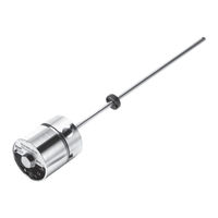
Magnetostriktives Positionsmesssystem-Bauform Stab
Marke:
Balluff
| Kategorie:
Industrielle Ausrüstung
| Dateigröße: 8.51 MB
Inhaltsverzeichnis
Deutsch
7
Eu Declaration of Conformity
3
EU-Konformitätserklärung
3
Inhaltsverzeichnis
7
Druckfeste Kapselung
8
Bedeutung der Warnhinweise
9
Benutzerhinweise
9
Btl7-A/E501-M
9
Entsorgung
9
Zündschutzart "Db" und "T" Druckfeste Kapselung
9
Sicherheitshinweise ATEX
10
Lieferumfang
9
Qualifiziertes Personal
9
Sprachen
9
Verwendete Symbole und Konventionen
9
Bestimmungsgemäße Verwendung
10
Nichtbestimmungsgemäße Verwendung
10
Sicherheitsmaßnahmen
10
Zulassungen, Normen und Konformität
10
Einsatz und Prüfung
11
Gerätekategorie und Eignung
11
Iecex-Zertifikat
12
Besondere Bedingungen Symbol „X
12
Dokumente des Betreibers
12
Montage, Installation und Einrichten
12
Wartung, Prüfung und Reparatur
12
Aufbau und Funktion
13
Aufbau
13
Funktion
14
Einbau und Anschluss
15
Applikation 1: Außerhalb Zone
15
Einbauvarianten
15
Einbau Vorbereiten
15
BTL Einbauen
16
Mindestabstand zu Festen Hindernissen
15
Applikation 2: Füllstandsmessungen in Zone
16
Einbau Vorbereiten
16
Positionsmesssystem Einbauen
16
Elektrischer Anschluss
18
Elektronikmodul Austauschen
18
Schirmung und Kabelverlegung
19
Inbetriebnahme
20
Hinweise zum Betrieb
20
Konfiguration mit dem Micropulse Configuration Tool
21
System in Betrieb Nehmen
20
Anschluss der USB-Kommunikationsbox
21
Konfigurationsmöglichkeiten
21
Einstellen mit der Einstellvorrichtung
22
Micropulse Configuration Tool
21
Hinweise zum Einstellvorgang
22
10
30
Übersicht der Einstellverfahren
23
Teach-In
23
Justieren
24
Reset
24
Teach-In mit der Einstellvorrichtung
25
Justieren mit der Einstellvorrichtung
26
Rücksetzen aller Werte mit der Einstellvorrichtung (Reset)
29
Technische Daten
30
11
30
Genauigkeit
30
Umgebungsbedingungen
30
Spannungsversorgung (Extern)
30
Ausgang
30
Kommunikationsleitungen La, Lb
30
Maße, Gewichte
31
Zubehör
33
12
33
Positionsgeber
33
USB-Kommunikationsbox
33
Einstellvorrichtung
33
13
35
Leitungsadapter
33
Typenschlüssel
34
Anhang
35
14
35
Umrechnung Längeneinheiten
35
Typenschild
35
English
39
Btl7-A/E501-M
41
Disposal
41
ATEX Safety Notes
42
Explanation of the Warnings
41
Languages
41
Qualified Personnel
41
Scope of Delivery
41
Symbols and Conventions
41
Approvals, Standards, and Conformity
42
Intended Use
42
Non-Intended Use
42
Safety Measures
42
Use and Inspection
43
Device Category and Suitability
43
Iecex Certificate of Conformity
44
Special Conditions ("X" Symbol)
44
Operator Documents
44
Assembly, Installation, and Setup
44
Maintenance, Inspection, Repair
44
Construction and Function
45
Construction
45
Function
46
Component Overview
46
Installation and Connection
47
Application 1: Outside Zone
47
Installation Guidelines
47
Preparing for Installation
47
Installing the BTL
48
Minimum Distance to Fixed Obstacles
47
Application 2: Fill Level Measurement in Zone
48
Preparing for Installation
48
Installing the Position Measuring System
48
Electrical Connection
50
Replacing Electronics Module
50
Shielding and Cable Routing
51
Startup
52
Operating Notes
52
Configuration with the Micropulse Configuration Tool
53
Starting up the System
52
Configuration Options
53
Adjust with the Calibration Device
54
Connecting the USB Communication Box
53
Micropulse Configuration Tool
53
Calibration Device
54
Calibration Procedure Notes
54
10
62
Calibration Procedure Overview
55
Teach-In
55
Adjust
56
Reset
56
Teach-In with the Calibration Device
57
Adjust with the Calibration Device
58
Reset All Values with the Calibration Device (Reset)
61
Technical Data
62
11
62
Accuracy
62
Ambient Conditions
62
Supply Voltage (External)
62
Output
62
Communication Lines La, Lb
62
Dimensions, Weights
63
Accessories
64
12
64
Floats
64
Magnets
65
USB Communication Box
65
Calibration Device
65
13
67
Conduit Adapter
65
Type Code
66
Appendix
67
14
67
Converting Units of Length
67
Part Label
67
Français
71
Btl7-A/E501-M
73
Elimination
73
Mode de Protection
73
Consignes de Sécurité ATEX
74
Fourniture
73
Langues
73
Qualification du Personnel
73
Signification des Avertissements
73
Symboles et Conventions Utilisés
73
Homologations, Normes et Conformité
74
Mesures de Sécurité
74
Utilisation Conforme aux Prescriptions
74
Utilisation Non Conforme aux Prescriptions
74
Utilisation et Contrôle
75
Catégorie D'appareils et Aptitude
75
Certificat Iecex
76
Conditions Particulières (Symbole « X »)
76
Documents de L'exploitant
76
Maintenance, Inspection et Réparation
76
Structure et Fonctionnement
77
Montage, Installation et Réglage
76
Fonctionnement
78
Montage et Raccordement
79
Application 1 : Hors de la Zone
79
Variantes de Montage
79
Préparation du Montage
79
Montage du BTL
80
Distance Minimale aux Obstacles Fixes
79
Application 2 : Mesures du Niveau de Remplissage en Zone
80
Préparation du Montage
80
Montage du Système de Mesure de Position
80
Remarques Importantes
80
Raccordement Électrique
82
Remplacement du Module Électronique
82
Blindage et Pose des Câbles
83
Conseils D'utilisation
84
Configuration Avec Micropulse Configuration Tool
85
Mise en Service du Système
84
Micropulse Configuration Tool
85
Possibilités de Configuration
85
Réglage à L'aide du Dispositif de Réglage
86
Raccordement du Module de Communication USB
85
Dispositif de Réglage
86
Remarques Concernant la Procédure de Réglage
86
10
94
Aperçu des Procédures de Réglage
87
Apprentissage
87
Ajustage
88
Réinitialisation (« Reset »)
88
Apprentissage à L'aide du Dispositif de Réglage
89
Ajustage à L'aide du Dispositif de Réglage
90
Réinitialisation de L'ensemble des Valeurs (« Reset ») à L'aide du Dispositif de Réglage
93
Caractéristiques Techniques
94
11
94
Précision
94
Conditions Ambiantes
94
Alimentation Électrique (Externe)
94
Sortie
94
Câbles de Communication la et Lb
94
Dimensions, Poids
95
Accessoires
96
12
96
Flotteurs
96
Capteur de Position
97
Module de Communication USB
97
Dispositif de Réglage
97
13
99
Adaptateur pour Câble
97
Code de Type
98
Annexe
99
14
99
Conversion Unités de Longueur
99
Plaque Signalétique
99
Italiano
103
Avvertenze Per L'utente
105
Fornitura
105
Lingue
105
Personale Qualificato
105
Significato Delle Avvertenze
105
Simboli E Segni Utilizzati
105
Smaltimento
105
Indicazioni DI Sicurezza ATEX
106
Misure DI Sicurezza
106
Omologazioni, Norme E Conformità
106
Uso Conforme
106
Utilizzo Non Conforme
106
Impiego E Verifica
107
Categoria Dispositivo E Omologazione
107
Certificato Iecex
108
Condizioni Particolari Simbolo "X
108
Documenti Dell'utente
108
Manutenzione, Collaudo E Riparazioni
108
Struttura E Funzionamento
109
Montaggio E Installazione
108
Funzionamento
110
Montaggio E Collegamento
111
Applicazione 1: al DI Fuori Della Zona
111
Varianti DI Montaggio
111
Preparazione del Montaggio
111
Montaggio BTL
112
Distanza Minima da Ostacoli Fissi
111
Applicazione 2: Misurazioni del Livello DI Riempimento Nella Zona
112
Preparazione del Montaggio
112
Montaggio Sensore DI Posizionamento Lineare
112
Collegamento Elettrico
114
Sostituzione Modulo Elettronico
114
Schermatura E Posa Dei Cavi
115
Messa in Funzione
116
Avvertenze Per Il Funzionamento
116
Configurazione con Il Micropulse Configuration Tool
117
Messa in Funzione del Sistema
116
Collegamento Dell'interfaccia DI Comunicazione USB
117
Micropulse Configuration Tool
117
Possibilità DI Configurazione
117
Impostazione con Il Dispositivo DI Regolazione
118
Avvertenze Sulla Procedura DI Regolazione
118
Dispositivo DI Regolazione
118
10
126
Prospetto Delle Procedure DI Regolazione
119
Teach-In
119
Calibrazione
120
Reset
120
Teach-In con Dispositivo DI Regolazione
121
Calibrazione con Il Dispositivo DI Regolazione
122
Ripristino DI Tutti I Valori con Il Dispositivo DI Regolazione (Reset)
125
Dati Tecnici
126
11
126
Precisione
126
Condizioni Ambientali
126
Tensione DI Alimentazione (Esterna)
126
Uscita
126
Linee DI Comunicazione La, Lb
126
Dimensioni, Pesi
127
Accessori
128
12
128
Galleggianti
128
Datore DI Posizione
129
Interfaccia DI Comunicazione USB
129
Dispositivo DI Regolazione
129
13
131
Adattatore Linea
129
Legenda Codici DI Identificazione
130
Appendice
131
14
131
Conversione Delle Unità DI Lunghezza
131
Targhetta DI Identificazione
131
Español
135
Eliminación de Desechos
137
Indicaciones de Seguridad ATEX
138
Idiomas
137
Indicaciones para el Usuario
137
Personal Cualificado
137
Significado de las Advertencias
137
Símbolos y Convenciones Utilizados
137
Volumen de Suministro
137
Homologaciones, Normas y Conformidad
138
Medidas de Seguridad
138
Uso Debido
138
Uso Indebido
138
Empleo y Comprobación
139
Categoría de Equipos E Idoneidad
139
Certificado Iecex
140
Símbolo "X" para Condiciones Especiales
140
Documentos del Explotador
140
Mantenimiento, Comprobación y Reparación
140
Estructura y Funcionamiento
141
Montaje, Instalación y Configuración
140
Funcionamiento
142
Montaje y Conexión
143
Aplicación 1: Fuera de la Zona
143
Variantes de Montaje
143
Preparación del Montaje
143
Montar el BTL
144
Distancia Mínima con Obstáculos Sólidos
143
Aplicación 2: Mediciones de Nivel de Llenado en Zona
144
Preparación del Montaje
144
Montar el Sistema de Medición de Posición
144
Conexión Eléctrica
146
Sustituir el Módulo Electrónico
146
Blindaje y Tendido de Cables
147
Puesta en Servicio
148
Indicaciones sobre el Servicio
148
Configuración con la Micropulse Configuration Tool
149
Puesta en Servicio del Sistema
148
Conexión del Módulo de Comunicación USB
149
Micropulse Configuration Tool
149
Posibilidades de Configuración
149
Ajuste con el Dispositivo de Ajuste
150
Dispositivo de Ajuste
150
Indicaciones Acerca del Proceso de Ajuste
150
10
158
Vista General de Los Procedimientos de Ajuste
151
Aprendizaje
151
Ajuste
152
Reset
152
Aprendizaje con el Dispositivo de Ajuste
153
Ajuste de Valores con el Dispositivo de Ajuste
154
Reposición de todos Los Valores con el Dispositivo de Ajuste (Reset)
157
Datos Técnicos
158
11
158
Precisión
158
Condiciones Ambientales
158
Alimentación de Tensión (Externa)
158
Salida
158
Líneas de Comunicación La, Lb
158
Medidas, Pesos
159
Accesorios
160
12
160
Flotador
160
Sensor de Posición
161
Módulo de Comunicación USB
161
Dispositivo de Ajuste
161
13
163
Adaptador de Cable
161
Código de Modelo
162
Anexo
163
14
163
Conversión de Unidades de Longitud
163
Placa de Características
163
汉语
167
Btl7-A/E501-M
169
供货范围
169
具备资质的人员
169
废弃处理
169
Atex安全提示
170
所使用的符号和惯例
169
磁致伸缩位置测量系统 - 杆式结构
169
用户提示
169
警告提示的意义
169
不符合规定的使用
170
安全措施
170
许可、标准和一致性
170
使用和检测
171
设备类别和适用性
171
Iecex证书
172
特殊条件符号"X
172
运营方文档
172
维护、检测和维修
172
结构与功能
173
安装和连接
175
安装类型
175
准备安装
175
安装Btl
176
准备安装
176
安装位置测量系统
176
装配、安装和设置
172
更换电子模块
178
电气连接
178
屏蔽与布线
179
运行提示
180
使用微脉冲配置工具进行配置
181
连接Usb通信盒
181
配置方法
181
使用调节装置设置
182
10
190
调节过程提示
182
使用调节装置示教
185
使用调节装置校准
186
使用调节装置复位所有数值 (复位)
189
技术参数
190
11
190
环境条件
190
供电 (外部)
190
输出端
190
通信线路La、Lb
190
尺寸、重量
191
12
193
位置指示器
193
Usb通信盒
193
调节装置
193
导线适配接头
193
型号编码
194
13
195
14
195
长度单位换算表
195
Руководство По Эксплуатации
197
Русский
199
Btl7-A/E501-M
201
Значение Предупреждающих Указаний
201
Используемые Символы И Условные Обозначения
201
Квалифицированный Персонал
201
Комплект Поставки
201
Сфера Действия
201
Утилизация
201
Указания По Безопасности ATEX
202
Языки
201
Допуски, Стандарты И Соответствие Требованиям
202
Использование Не По Назначению
202
Использование По Назначению
202
Меры Предосторожности
202
Применение И Проверка
203
Категория Приборов И Пригодность
203
Сертификат Iecex
204
Особые Условия: Символ «X
204
Документация Эксплуатирующей Стороны
204
Монтаж, Подключение И Наладка
204
Техническое Обслуживание, Проверка И Ремонт
204
Конструкция И Принцип Действия
205
Конструкция
205
Принцип Действия
206
Монтаж И Подключение
207
Минимальное Расстояние До Закрепленных Препятствий
207
Применение 1: За Пределами Зоны
207
Варианты Монтажа
207
Подготовка К Монтажу
207
Монтаж BTL
208
Применение 2: Измерение Уровня Наполнения В Зоне
208
Подготовка К Монтажу
208
Монтаж Системы Измерения Перемещений
208
Замена Электронного Модуля
210
Подключение Электропитания
210
Экранирование И Прокладка Кабеля
211
Ввод В Эксплуатацию
212
Ввод В Эксплуатацию Системы
212
Указания По Эксплуатации
212
Конфигурирование С Помощью «Micropulse Configuration Tool
213
Возможности Конфигурирования
213
Настройка С Помощью Приспособления Для Настройки
214
Подключение Блока Связи USB
213
Программа «Micropulse Configuration Tool
213
Приспособление Для Настройки
214
Указания К Процессу Настройки
214
10
222
Обзор Методов Настройки
215
Обучение
215
Юстировка
216
Сброс
216
Обучение С Помощью Приспособления Для Настройки
217
Юстировка С Помощью Приспособления Для Настройки
218
Сброс Всех Значений С Помощью Приспособления Для Настройки
221
Технические Характеристики
222
11
222
Условия Окружающей Среды
222
Напряжение Электропитания (Внешнего)
222
Выход
222
Линии Связи La, Lb
222
Размеры, Вес
223
Принадлежности
224
12
224
Поплавок
224
Монтажное Положение
224
Датчик Положения
225
Блок Связи USB
225
Приспособление Для Настройки
225
13
227
Переходники Для Проводов
225
Типовой Код
226
Приложение
227
14
227
Пересчет Единиц Длины
227
Заводская Табличка
227
Werbung
Balluff BTL7-A501-M J-DEXC-TA12 Serie Betriebsanleitung (226 Seiten)
Magnetostriktives Positionsmesssystem
Marke:
Balluff
| Kategorie:
Messgeräte
| Dateigröße: 20.2 MB
Werbung
Verwandte Produkte
Balluff BTL7-A501-M Serie
Balluff BAE SA-OH-059-YI-DP02
Balluff BAE SA-OH-059-YI-S75G
Balluff BAM GM-ML-01-C04
Balluff BAV MA-NC-00028-05
Balluff BIC 1I0-I2A50-M30MI3-SM4A4A
Balluff BIC 1I12-P2A25-M30MI1-BPX05-110
Balluff Kategorien
Sensoren
Messgeräte
Module
Netzwerkhardware
Industrielle Ausrüstung
Weitere Balluff Anleitungen
Anmelden
Anmelden
ODER
Mit Facebook anmelden
Mit Google anmelden
Anleitung hochladen
Von PC hochladen
Von URL hochladen