Inhaltsverzeichnis
Werbung
Quicklinks
Werbung
Inhaltsverzeichnis

Verwandte Anleitungen für Horizon Hobby Cirrus SR22T 30cc


Inhaltszusammenfassung für Horizon Hobby Cirrus SR22T 30cc
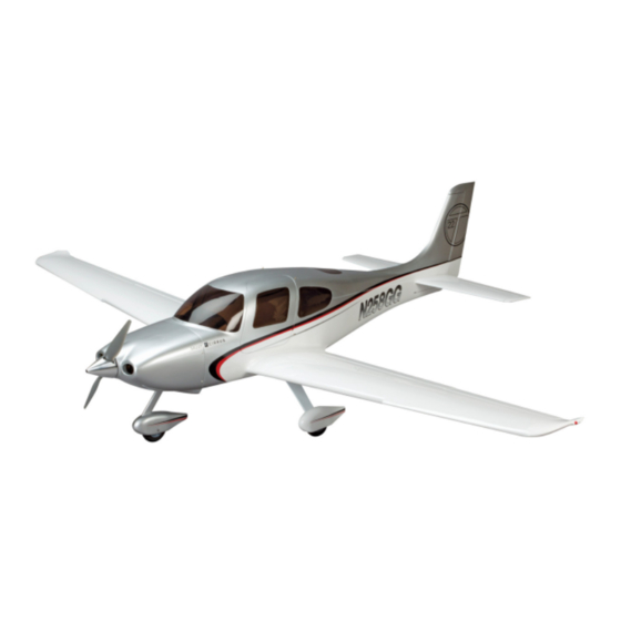
- Seite 1 Cirrus SR22T 30cc Instruction Manual Bedienungsanleitung...
-
Seite 2: Using The Manual
Alle Anweisungen, Garantien und anderen zugehörigen Dokumente können im eigenen Ermessen von Horizon Horizon Hobby, Inc. For up-to-date product literature, visit horizonhobby. com and click on the support tab for Hobby, Inc. jederzeit geändert werden. Die aktuelle Produktliteratur finden Sie auf horizonhobby.com unter der this product. -
Seite 3: Safety Warnings And Precautions
Sie bitte die Produkt- oder Bedienungsanweisung oder Flight groß genug ist. kontaktieren den Service von Horizon Hobby. • Make sure this area is clear of friends and spectators Fly only in open areas to ensure safety. It is recommended prior to launching your aircraft. - Seite 4 SpecificationS•Spezifikationen Large partS Layout•BauteiLe (ohne kLeinteiLe) 97.0 in (246cm) 930 sq in (60.0 dm2) 66.0 in (167cm) 16.3–18.0 lb (7.40–8.20 kg) 2-Stroke Gasoline/Petrol: 33cc 2-Takt Benziner: 33cc 4-Stroke Gasoline/Petrol: 30cc 4 Takt Benziner: 30cc Electric Power•Elektro Antrieb Power Power 160 Brushless 5-channel (or greater) with 9 servos, 8 for EP 5-Kanal (oder größer) mit 9-Servos, 8 für Elektroantrieb Spinner•Spinner 3 inch, 2-blade (included•inklusive)
- Seite 5 repLacement partS•erSatzteiLe faStenerS•VerBinDungSeLemente part english deutsch HAN502001 Fuselage GFK Rumpf Flat Washer Lock Nut HAN502002 Left Wing with Aileron and Flap Tragfläche links Unterlegscheibe Stopmutter HAN502003 Right Wing with Aileron and Flap Tragfläche rechts HAN502004 Stabilizer and Elevator Set Höhenruder Self-Tapping Screw Metal clevis HAN502005...
- Seite 6 aSSemBLy SymBoL guiDe•montage SymBoLe Apply threadlock Ensure free rotation Use medium CA Use a pencil Schraubensicherungslack verwenden Rotation sicherstellen Mittelflüssigen Verwenden Sie einen Bleistift Sekundenkleber verwenden Assemble right and left Push tightly Use thin CA Use a felt-tipped pen Links und rechts montieren Fest drücken Dünnflüssigen Verwenden Sie einen Faserstift...
- Seite 7 requireD raDio equipment•erforDerLiche rc auSrüStung eLectric power•eLektroantrieB english deutsch english deutsch SPMAR8000 Spektrum AR8000 8-Channel DSMX Receiver AR8000 8-Kanal DSMX Receiver EFLM4160A Power 160 Brushless Outrunner Motor, 245Kv Power 160 Brushless Outrunner-Motor, ™ ® 245-Kv JRPA004 Chargeswitch Ladestecker ® 80-Amp (or greater) ESC for Brushless Outrunner 80A (oder großer) Regler /ESC für JRPB5006 Receiver Pack 2500mAh, 6V Ni-MH...
-
Seite 8: Before Starting Assembly
requireD tooLS•BenötigteS werkzeug before starting asseMbly vor deM zUsaMMenbaU english deutsch • Remove parts from bag. • Entnehmen Sie zur Überprüfung jedes Teil der Verpackung. Drill Bohrer • Inspect fuselage, wing panels, rudder and stabilizer for • Überprüfen Sie den Rumpf, Tragflächen, Seiten- und damage. - Seite 9 controL Surface hinging•anSchLagen Der ruDer 4 6 1 3 Fit all the hinges in the control surface, checking their alignment. Make any adjustments necessary to correctly Separate the elevator from the stabilizer. Note the two hinges position each hinge.
- Seite 10 7 8 9 aiLeron anD fLap inStaLLation• einbaU der QUerrUder Und klappen 1 Prepare and install the hinges in the aileron at this time following the same procedure as the elevator hinges. Make sure to position each hinge correctly so the aileron can move Fit the aileron to the wing.
- Seite 11 2 3 4 6 Insert the M3 x 8 socket head screws into the hinge, then slide Fit the remaining hinges to the wing. Fit the hinges together an M3 washer on the screw. Note that the heads of the screws using the screws placed in the flap hinges earlier.
- Seite 12 8 10 11 12 Check the operation of the flap. It must move smoothly Fit the hinges to the flap and wing. Check the alignment as through the range of motion shown in the control throw described, then use a paper towel and isopropyl alcohol to section of this manual.
- Seite 13 aiLeron SerVo anD Linkage•querruDerSerVo unD anLenkung 4 6 1 3 Use a hobby knife to carefully cut the slot for the control horn. Use a pin vise and 1/16-inch (1.5mm) drill bit to drill through Use care not to cut through the top of the control surface. the holes in the servo cover and into the support for the Align a ruler along the center of the servo arm slot.
- Seite 14 8 10 12 14 Apply a small amount of thin CA to harden the threads made Position the servo on the cover so the servo arm is centered in Glue the 20 x 20 x 10mm servo mounting blocks to the servo Remove the servo from the cover.
- Seite 15 16 18 20 22 Apply a small amount of thin CA to harden the threads made Secure an 18-inch (457mm) extension to the servo lead using Carefully pull the servo lead and extension through the wing Cut a 1/4-inch (6mm) piece of silicone tubing as shown.
- Seite 16 24 fLap SerVo anD Linkage•kLappenSerVo unD anLenkung 5 1 3 M2.5 x 10 Center the servo using the radio system. Connect the linkage Thread a screw into each of the holes in the flap servo cover between the servo and control horn.
- Seite 17 6 8 9 11 Apply a small amount of thin CA to harden the threads made Mark the location of the servo on the servo cover so the Position the servo between the blocks. With a gap of 1/32 inch in the previous step.
- Seite 18 13 15 17 19 Thread a servo mounting screw into each of the holes in Secure the servo to the blocks using the screws provided with Assemble the linkage for the aileron using the hardware the flap servo mounting holes. Remove the screws before the servo.
- Seite 19 20 21 ruDDer anD ruDDer SerVo inStaLLation• einbaU des seitenrUders Und seitenrUderservos 1 Secure the servo cover to the wing using four M2.5 x 10 self- tapping screws. Schrauben Sie die Servoklappe an die Tragfläche mit den vier M2.5 x 10 selbstschneidenen Schrauben.
- Seite 20 2 4 5 6 Fit the rudder to the fin. The rudder will need to be deflected Thread a servo mounting screw into each of the holes in as shown to get the hinges to align and still clear the balance the rudder servo mounting holes.
- Seite 21 8 10 12 14 Connect the rudder servo to the receiver and use the radio Slide a sleeve onto the end of the cable, then slide the cable Insert the coupler end into the fuselage. system to center the rudder servo. Attach a large servo arm through the hole in the coupler end.
- Seite 22 16 18 20 eLeVator SerVo anD Linkage• höhenruDerSerVo unD anLenkung 1 Repeat the process of installing the couplers to complete the connection to the rudder control horn. There will be light tension on the cables when the rudder is centered. Place light tension on the cable, pulling it straight rearward Glue the control horns into the rudder using epoxy.
- Seite 23 3 5 7 8 M2.5 x 10 Glue the control horn into the elevator using epoxy. Use the same procedure for gluing the aileron control horns to glue the elevator control horn into position. This ensures a good bond Use a hobby knife to carefully cut the slot for the control horn.
- Seite 24 9 11 13 14 Prepare the elevator servos by installing the grommets and eyelets. Center the servos using the radio system, then install the servo arms so they are perpendicular to the servo center Mark the location of the servo on the servo cover so the Position the servo between the blocks.
- Seite 25 15 17 19 21 Secure the servo to the blocks using the screws provided with the servo. Thread a servo mounting screw into each of the holes in the Cut a 1/4-inch (6mm) piece of silicone tubing as shown. Slide Center the servo using the radio system.
- Seite 26 StaBiLizer inStaLLation•einBau DeS höhenLeitwerkS 4 6 1 3 Assemble the elevator extension by securing a Y-harness to Slide the joiner rods into the fuselage slightly, then secure the a 24-inch (609mm) extension. Insert the extension into the elevator servo to the extension using string or a commercially fuselage, then tape the ends of the Y-harness to the sides available retainer.
-
Seite 27: Montage Des Fahrwerks
receiVer anD receiVer Battery inStaLLation•einBau Von empfänger unD empfängerakku main LanDing gear inStaLLation• Montage des fahrwerks 1 3 4 1 Remove the four screws holding the plywood cover inside the Install the steering servo in the fuselage next to the receiver Connect the leads to the receiver. - Seite 28 2 3 4 6 Use a flat file to make a 1/4-inch (6mm) flat area on the axle. Slide the wheel on the axle, then secure it using another wheel Secure the main landing gear in the fuselage. Install the collar and setscrew.
- Seite 29 noSe gear inStaLLation•einBau Den BugraDS 5 7 1 3 Slide a wheel collar on the nose gear wire. Insert the wire Remove the steering arm and wheel collar from the nose gear through the bracket, then place the steering arm on the wire. wire.
- Seite 30 9 11 13 ep motor inStaLLation• e-Motor einbaU 1 Remove the steering pushrod and make a Z-bend in the wire. Fit the steering pushrod back into the fuselage, this time from Trim any excess wire using side cutters. inside the fuselage.
- Seite 31 3 5 7 gaS engine inStaLLation• einbaU verbrenner 1 M4 x 25 Attach the ESC to the motor box using hook and loop tape, tie wraps or screws as appropriate. Solder connectors as needed to connect the speed control to the motor and battery. Drill Use an mounting screw with a washer to draw the blind Attach the propeller adapter and X-mount to the motor.
- Seite 32 3 5 6 8 Remove the template from the firewall. Enlarge the holes Mount the ignition module to the front of the fuselage. Use tie Drill a 1/4-inch (6mm) hole near the nose gear bracket for the Connecting the throttle linkage follows the same procedure as for the engine mounting screws using a drill and 7/32-inch wraps (not included) and hook and loop tape (not included) to...
- Seite 33 fueL tank inStaLLation•einBau kraftStofftank 3 5 1 2 Cut a piece of fuel line and secure it to one of the shorter Insert the tank into the fuselage, guiding the tubing through M3 x 20 tubes using a piece of wire. Secure the clunk to the tubing, the hole in the firewall.
- Seite 34 cowLing inStaLLation•anBau Der motorhauBe 3 5 1 2 M3 x 10 Attach the spinner to the engine. Make sure the spinner cutouts do not contact the propeller blades. Slide the cowling into position. Trim the cowling to clear the Use a pin vise and a 5/64-inch (2mm) drill bit to drill four Mount the muffler and trim the cowling to clear.
- Seite 35 finaL aSSemBLy•enDmontage 2 4 1 Fit the instrument panel into the fuselage. Use silicone Slide the wing into position, guiding the leads for the flap and adhesive to glue the instrument panel into the fuselage. aileron into the fuselage. Connect the leads, then use the wing Use hobby scissors to trim the instrument panel to fit into the bolt to secure the wing to the fuselage.
- Seite 36 DecaL inStaLLation•aufkLeBen DeS DekorBogen Apply the decals to your model using the photos located in this section of the manual and the box art from your model. Use a spray bottle and a drop of dish washing liquid or glass cleaner sprayed in the location of the decal to allow repositioning of the decal.
-
Seite 37: Center Of Gravity
center of gravity der schwerpUnkt An important part of preparing the aircraft for flight is properly balancing the model. Ein sehr wichtiger Teil in der Flugvorbereitung ist es das Flugzeug richtig auszubalancieren. 1. Attach the wing panels to the fuselage. Make sure to connect the leads from the ailerons and flaps to the appropriate leads 1. -
Seite 38: Control Throws
control throws ruDerauSSchLäge 1. Turn on the transmitter and receiver of your model. Check the movement of the rudder using the transmitter. When the stick 1. Schalten Sie den Sender und Empfänger ihres Modells ein. Prüfen Sie die Seitenruderaussschläge mit dem Sender. is moved to the right, the rudder should also move right. -
Seite 39: Preflight Checklist
preflight checklist vorflUgkontrolle daily flight checks tägLicher fLug check • C harge the transmitter, receiver and motor battery for • L aden Sie den Sender- ,Empfänger- und Zündakku für • C heck the battery voltage of the transmitter battery. Do • Ü berprüfen Sie die Spannung des Senderakkus. Fliegen your airplane. Use the recommended charger supplied Ihr Flugzeug. Verwenden Sie für die RC Anlage bitte not fly below the manufacturer’s recommended voltage. -
Seite 40: Limited Warranty
By the act at our facility. An Online Service Request is available at Express, and Discover cards. By submitting any item to service by anyone other than a Horizon Hobby authorized of use, setup or assembly, the user accepts all resulting http://www.horizonhobby.com/content/_service-center_ Horizon for service, you are agreeing to Horizon’s Terms and... -
Seite 41: Sicherheitshinweise
Sollten wir nach 90 Tagen keineEinverständniserklärung zur aus. Rücksendungen durch den Käufer direkt an Horizon oder Exklusive Garantie ¬ Horizon Hobby Inc (Horizon) Muss Ihr Produkt gewartet oder repariert werden, wenden Sie Reparatur vorliegen haben, behalten wir uns vor, das Produkt eine seiner Landesvertretung bedürfen der Schriftform. -
Seite 42: Instructions For Disposal Of Weee By Users In The European Union
Horizon Technischer Service 25337 Elmshorn, Germany service@horizonhobby.de Room 506, No. 97 Changshou Rd. +86 (021) 5180 9868 China Horizon Hobby – China 11 Rue Georges Charpak +33 (0) 1 60 18 34 90 Shanghai, China 200060 info@horizonhobby.com.cn France Horizon Hobby SAS 77127 Lieusaint, France infofrance@horizonhobby.com... -
Seite 43: Ama National Model Aircraft Safety Code
aMa national Model aircraft safety code effective January 1, 2011 B. raDio controL (rc) (h) Not operate model aircraft while under the influence of 7. Under no circumstances may a pilot or other person touch alcohol or while using any drug which could adversely affect a model aircraft in flight while it is still under power, except a. - Seite 44 The Spektrum trademark is used with permission of Bachmann Industries, Inc. Cirrus and associated emblems, logos and body designs, are either trademarks or registered trademarks of Cirrus Design Corporation and are used under license by Horizon Hobby, Inc. All other trademarks, service marks and logos are the property of their respective owners.