HomeMatic IP HmIP-FAL230-C6 Installations- Und Bedienungsanleitung
Fußbodenheizungscontroller 6 kanäle, 230 v
Vorschau ausblenden
Andere Handbücher für HmIP-FAL230-C6:
- Installations- und bedienungsanleitungen (42 Seiten)
Inhaltsverzeichnis
Fehlerbehebung

Verwandte Anleitungen für HomeMatic IP HmIP-FAL230-C6


Inhaltszusammenfassung für HomeMatic IP HmIP-FAL230-C6
- Seite 1 Installations- und Bedienungsanleitung Installation instruction and operating manual Fußbodenheizungscontroller – S. 2 6 Kanäle, 230 V Floor Heating Controller – p. 44 6 channels, 230 V HmIP-FAL230-C6...
-
Seite 2: Lieferumfang
Lieferumfang Anzahl Bezeichnung Homematic IP Fußbodenheizungscontroller – 6 Kanäle, 230 V Schrauben 4,0 x 40 mm Dübel 6 mm Bedienungsanleitung Dokumentation © 2016 eQ-3 AG, Deutschland Alle Rechte vorbehalten. Ohne schriftliche Zustimmung des Herausgebers darf diese Anleitung auch nicht auszugsweise in... - Seite 6 Selecttaste drücken press select button Systemtaste drücken press system button...
-
Seite 7: Inhaltsverzeichnis
Anlernen ................20 6.4.1 Anlernen an den Homematic IP Wandthermos- taten ................20 6.4.2 Anlernen an die Homematic IP Multi IO Box ... 22 6.4.3 Einen weiteren Fußbodenheizungscontroller hinzufügen .............. 22 6.4.4 Anlernen an den Homematic IP Access Point . 23 Konfiguration über den Homematic IP Wandther-... - Seite 8 10.2 Duty Cycle ................36 10.3 Fehlercodes und Blinkfolgen ..........37 10.3.1 Blinkfolgen der System-LED (A) ......37 10.3.2 Blinkfolgen der Kanal-LED ........39 Wiederherstellung der Werkseinstellungen ....39 12 Wartung und Reinigung ..........40 13 Allgemeine Hinweise zum Funkbetrieb .....41 14 Technische Daten ............41...
-
Seite 9: Hinweise Zur Anleitung
Hinweise zur Anleitung Hinweise zur Anleitung Lesen Sie diese Anleitung sorgfältig, bevor Sie Ihr Home- matic IP Gerät in Betrieb nehmen. Bewahren Sie die An- leitung zum späteren Nachschlagen auf! Wenn Sie das Gerät anderen Personen zur Nutzung über- lassen, übergeben Sie auch diese Anleitung. Benutzte Symbole: Achtung! Hier wird auf eine Gefahr hingewiesen. - Seite 10 Gefahrenhinweise Betreiben Sie das Gerät nur in trockener sowie staubfreier Umgebung, setzen Sie es keinem Ein- fluss von Feuchtigkeit, Vibrationen, ständiger Sonnen- oder anderer Wärmeeinstrahlung, Kälte und keinen mechanischen Belastungen aus. Das Gerät ist kein Spielzeug! Erlauben Sie Kindern nicht damit zu spielen. Lassen Sie das Verpa- ckungsmaterial nicht achtlos...
- Seite 11 Gefahrenhinweise Arbeiten am 230-V-Netz dürfen nur von einer Elektrofachkraft (nach VDE 0100) erfolgen. Dabei sind die geltenden Unfallverhütungsvorschriften zu beachten. Zur Vermeidung eines elektrischen Schlages am Gerät, schalten Sie bitte die Netz- spannung frei (Sicherungsautomat abschalten). Bei Nichtbeachtung der Installationshinweise können Brand oder andere Gefahren entstehen.
-
Seite 12: Funktion Und Geräteübersicht
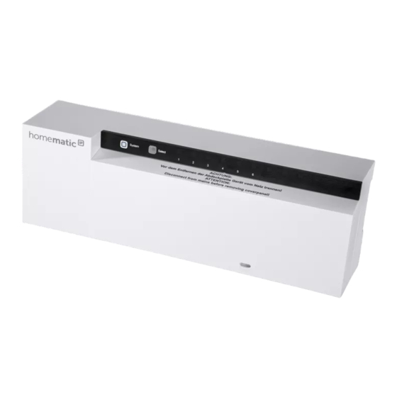
Mit dem Homematic IP Fußbodenheizungscontroller können Sie Ihre Fußbodenheizung Raum für Raum kom- fortabel und bedarfsgerecht per Smartphone App oder mit dem Homematic IP Wandthermostaten steuern und so die Raumtemperatur auf Ihre individuellen Bedürfnisse anpassen. Der Fußbodenheizungscontroller kann zur Steuerung... - Seite 13 Sie können das Gerät flexibel mit den mitgelieferten Schrauben oder einfach auf einer Hutschiene montie- ren. Dank der sicheren Funkkommunikation zwischen den Homematic IP Geräten beschränkt sich der Verdrah- tungsaufwand auf ein Minimum. Geräteübersicht (s. Abbildung 1): Systemtaste (Anlerntaste und LED) Selecttaste (Kanaltaste und LED) Öffnungsschlitz...
-
Seite 14: Allgemeine Systeminformationen
Allgemeine Systeminformationen Allgemeine Systeminformationen Dieses Gerät ist Teil des Homematic IP Smart-Home-Sys- tems und kommuniziert über das Homematic IP Funk- protokoll. Alle Geräte des Systems können komfortabel und individuell per Smartphone über die Homematic IP App konfiguriert werden. Alternativ haben Sie die Mög- lichkeit, Homematic ... -
Seite 15: Hutschienenmontage
Inbetriebnahme Stellen Sie sicher, dass an der gewünschten Posi- tion in der Wand keine Leitungen verlaufen! • Zeichnen Sie zwei der Bohrlöcher im Anstand von 13,6 cm mit einem Stift an der Wand an (s. Abbildung 3). • Bohren Sie die vorgezeichneten Löcher mit ei- nem geeigneten Bohrer. - Seite 16 Inbetriebnahme Hinweis! Installation nur durch Personen mit einschlägigen elektrotechnischen Kenntnissen und Erfahrungen!* Durch eine unsachgemäße Installation gefährden Sie • Ihr eigenes Leben; • das Leben der Nutzer der elektrischen Anlage. Mit einer unsachgemäßen Installation riskieren Sie schwere Sachschäden, z. B. durch einen Brand. Es droht für Sie die persönliche Haftung bei Personen- und Sach- schäden.
- Seite 17 Inbetriebnahme Für den Einbau des Fußbodenheizungscontrollers in einen Stromkreisverteiler, muss das Gerät ent- sprechend VDE 0603, DIN 43871 (Niederspan- nungsunterverteilung (NSUV)), DIN 18015-x ein- gebaut werden. In diesem Fall muss die Montage auf einer Tragschiene (Hutschiene, DIN-Rail) lt. EN50022 erfolgen. Installation und Verdrahtung sind entsprechend VDE 0100 (VDE 0100-410, VDE 0100-510 usw.) durchzuführen.
-
Seite 18: Installation
Inbetriebnahme Starre Leitung [mm Flexible Leitung mit und ohne Aderendhülse [mm 0,75 – 1,50 0,75 – 1,50 Installation Für die Installation des Fußbodenheizungscontrollers ge- hen Sie wie folgt vor: • Öffnen Sie die Abdeckung (D), indem Sie die Ver- rastung unter dem Öffnungsschlitz (C) mit einem geeigneten Schraubendreher eindrücken und die Abdeckung nach oben abziehen (s. -
Seite 19: Verhalten Nach Einschalten Der Netzspannung
Inbetriebnahme • Achten Sie vor dem Verschließen der Abdeckung darauf, dass alle Anschlussleitungen ordnungs- gemäß in die vorgesehenen Kabelführungen ge- drückt sind. • Schließen Sie die Abdeckung wieder, indem Sie die Rastnasen der Abdeckung in die vorgesehenen Öffnungen schieben und die Abdeckung herunter- drücken. -
Seite 20: Anlernen
IP Access Point anlernen. Beim direkten Anlernen erfolgt die Konfiguration am Wandthermostaten und beim Anlernen an den Access Point über die Homematic IP App. 6.4.1 Anlernen an den Homematic IP Wandthermo- staten Halten Sie beim Anlernen einen Mindestabstand von 50 cm zwischen den Geräten ein. - Seite 21 Inbetriebnahme Wenn kein Anlernen erfolgt, wird der Anlernmo- dus automatisch nach 3 Minuten beendet. Wenn Sie den Fußbodenheizungscontroller an einen Homematic IP Wandthermostaten anlernen möchten, müssen die beiden zu verknüpfenden Geräte in den An- lernmodus gebracht werden. Dafür gehen Sie wie folgt vor: •...
-
Seite 22: Anlernen An Die Homematic Ip Multi Io Box
Inbetriebnahme 6.4.2 Anlernen an die Homematic IP Multi IO Box Wenn Sie den Fußbodenheizungscontroller an eine Homematic IP Multi IO Box anlernen möchten, müssen die beiden zu verknüpfenden Geräte in den Anlernmodus gebracht werden. Dafür gehen Sie wie folgt vor: Drücken Sie so oft kurz auf die Selecttaste (B), bis... -
Seite 23: Anlernen An Den Homematic Ip Access Point
6.4.4 Anlernen an den Homematic IP Access Point Richten Sie zunächst Ihren Homematic IP Access Point über die Homematic IP App ein, um weitere Homematic IP Geräte im System nutzen zu kön- nen. Ausführliche Informationen dazu finden Sie in der Bedienungsanleitung des Access Points. - Seite 24 Zum Anlernen des Fußbodenheizungscontrollers an den Access Point gehen Sie wie folgt vor: • Öffnen Sie die Homematic IP App auf Ihrem Smartphone. • Wählen Sie den Menüpunkt „Gerät anlernen“ aus. Drücken Sie kurz auf die Systemtaste (A), bis die •...
-
Seite 25: Konfiguration Über Den Homematic Ip Wandther- Mostaten
Die Konfiguration des Homematic IP Fußboden- heizungscontrollers ist mit dem Homematic IP Wandthermostaten (HmIP-WTH-2), über den Homematic IP Access Point in Verbindung mit der Smartphone App oder über die WebUI der Homematic Zentrale CCU3 möglich. Um den Fußbodenheizungscontroller über den Wand- thermostaten zu konfigurieren, gehen Sie wie folgt vor: •... - Seite 26 Konfiguration über den Homematic IP Wandthermostaten • Ist der Wandthermostat an mehr als einen Fuß- bodenheizungscontroller angelernt, wählen Sie mit dem Stellrad den gewünschten Fußboden- heizungscontroller aus. • Wählen Sie aus, ob Sie Geräteparameter („UnP1/ UnP2“) oder Kanalparameter („ChAn“) konfigurie- ren wollen.
- Seite 27 Konfiguration über den Homematic IP Wandthermostaten Geräteparameter UnP1: Parame- Index Wert Bedeutung Frost- P024 Frostschutz inaktiv schutz- 2,0 °C tempe- 2,5 °C ratur 8,0 °C (default) 9,5 °C 10,0 °C...
- Seite 28 Konfiguration über den Homematic IP Wandthermostaten Pumpensteuerung aktiv *4 Pumpen- P025 steue- Lastausgleich rung Pumpensteuerung aktiv *4 aktiv/ inaktiv, Lastausgleich Pumpensteuerung aktiv *4 Lastaus- gleich *1 / Lastsammlung Last- Pumpensteuerung aktiv *4 samm- lung *2 Lastsammlung Antriebs- Pumpensteuerung inaktiv (default)
- Seite 29 Konfiguration über den Homematic IP Wandthermostaten Notbe- P026 trieb im Heizmo- … 25 % (default) … 99 % 100 % Notbe- P032 0 % (default) trieb im Kühlmo- … … 99 % 100 % *1: Heizzonen werden (wenn möglich) gestaffelt ge- steuert.
- Seite 30 Konfiguration über den Homematic IP Wandthermostaten Geräteparameter UnP2: Parameter Index Wert Bedeutung Ventilschutz- P007 0 Minuten Funktions- 1 Minute Dauer 5 Minuten (default) 10 Minuten Ventilschutz- P051 0 Tage Funktions- 1 Tag Intervallzeit 14 Tage (default) 27 Tage 28 Tage...
- Seite 31 Konfiguration über den Homematic IP Wandthermostaten Dauer/ P007 0 Minuten Länge der 1 Minute (default) Pumpen- schutz- 9 Minuten funktion 10 Minuten (nur für Kanal 1 verfügbar) Ausschalt- P008 0 Minuten verzöge- 1 Minute 2 Minuten (default) rung der Pumpe (nur für...
- Seite 32 Konfiguration über den Homematic IP Wandthermostaten Luftfeuch- P050 40 %; Luftfeuchtigkeits- tigkeits- grenze inaktiv grenze … … 80 %; Luftfeuchtigkeits- grenze inaktiv 40 %; Luftfeuchtigkeits- grenze aktiv … … 60 %; Luftfeuchtigkeits- grenze aktiv (default) … … 80 %; Luftfeuchtigkeits-...
- Seite 33 Konfiguration über den Homematic IP Wandthermostaten Heizen im P053 Heizen im Heizmodus Heizmo- inaktiv dus aktiv/ Heizen im Heizmodus aktiv (default) inaktiv Aus- P055 FBH Standard (default) wahl der FBH Niedrigenergie häuslichen Radiator Gegeben- Konvektor passiv heiten Konvektor aktiv Vor- Luft- P178 40 %;...
-
Seite 34: Manuelle Bedienung
Manuelle Bedienung Manuelle Bedienung Heizzonen ein- bzw. ausschalten Zu Installations- und Testzwecken können die einzelnen Heizzonen manuell ein- bzw. ausgeschaltet werden. Um eine Heizzone manuell ein- bzw. auszuschalten, gehen Sie wie folgt vor: • Wählen Sie mit der Selecttaste (B) den gewünsch- ten Kanal aus (s. -
Seite 35: Geräteverknüpfungen Löschen
Geräteverknüpfungen löschen • Wollen Sie keine Änderung des Parameters vor- nehmen, können Sie das Menü über einen kurzen Tastendruck der Selecttaste (B) verlassen. • Um den Parameter von aktiv auf inaktiv bzw. von inaktiv auf aktiv umzustellen, drücken Sie für mind. -
Seite 36: Fehlerbehebung
Stunde (also 36 Sekunden in einer Stunde). Die Geräte dürfen bei Erreichen des 1-%-Limits nicht mehr senden, bis diese zeitliche Begrenzung vorüber ist. Gemäß dieser Richtlinie, werden Homematic IP Geräte zu 100 % nor- menkonform entwickelt und produziert. Im normalen Betrieb wird der Duty Cycle in der Regel nicht erreicht. -
Seite 37: Fehlercodes Und Blinkfolgen
Fehlerbehebung vermehrte und funkintensive Anlernprozesse der Fall sein. Eine Überschreitung des Duty-Cycle-Limits wird durch dreimal langes rotes Blinken der LED angezeigt und kann sich durch temporär fehlende Funktion des Gerätes äu- ßern. Nach kurzer Zeit (max. 1 Stunde) ist die Funktion des Gerätes wiederhergestellt. - Seite 38 Fehlerbehebung Kurzes Anlernmodus aktiv Geben Sie die oranges letzten vier Ziffern Blinken (alle der Geräte- 10 s) Seriennummer zur Bestätigung ein (s. „6.4 Pairing“ auf Seite 57). 1x langes Vorgang Versuchen Sie es rotes fehlgeschlagen erneut („10.1 Befehl Leuchten oder Duty-Cycle- nicht bestätigt“...
-
Seite 39: 10.3.2 Blinkfolgen Der Kanal-Led
Wiederherstellung der Werkseinstellungen 10.3.2 Blinkfolgen der Kanal-LED Blinkcode Bedeutung Lösung Langsames Notbetrieb aktiv Batterien des Blinken Wandthermostaten wechseln, Funktest durchführen, Wandthermostat ggf. neu positio- nieren, defekten Wandthermostaten austauschen Doppeltes, Funkverbindung Position des kurzes zum Wandther- Wandthermostaten Blinken mostaten gestört verändern oder einen Repeater einsetzen. -
Seite 40: Wartung Und Reinigung
Lassen Sie die Systemtaste wieder los, um das Wiederherstellen der Werkseinstellungen abzu- schließen. Das Gerät führt einen Neustart durch. Nach dem Neustart können Sie das Gerät wieder in Ihr Homematic IP System integrieren. Wartung und Reinigung Das Gerät ist wartungsfrei. Überlassen Sie eine War- tung oder Reparatur einer Fachkraft. -
Seite 41: Allgemeine Hinweise Zum Funkbetrieb
Gegebenheiten vor Ort eine wich- tige Rolle. Hiermit erklärt die eQ-3 AG, Maiburger Str. 29, 26789 Leer, Deutschland, dass der Funkanlagentyp Homematic IP HmIP-FAL230-C6 der Richtlinie 2014/53/EU entspricht. Der vollständige Text der EU-Konformitätserklärung ist unter der folgenden Internetadresse verfügbar: www.homematic-ip.com Technische Daten Geräte-Kurzbezeichnung:... - Seite 42 Technische Daten Aufbaumontage Anzahl Heizzonen: Anzahl Antriebe: 9 / (8) Anzahl Pumpen: Versorgungsspannung: 230 V/50 Hz Stromaufnahme: 6,3 A max. Schaltleistung je Heizzone: 1 A max. Nennlast aller Antriebe: 250 W max. Art der Abschaltung: Micro Leitungsart u. -querschnitt: starre und flexible Leitung, 0,75 - 1,5 mm²...
- Seite 43 Technische Daten 869,4–869,65 MHz Maximale Funk-Sendeleistung: 10 dBm Typ. Funk-Freifeldreichweite: 270 m Duty Cycle: < 1% pro h/< 10% pro h Technische Änderungen vorbehalten. Entsorgungshinweis Gerät nicht im Hausmüll entsorgen! Elektroni- sche Geräte sind entsprechend der Richtlinie über Elektro- und Elektronik-Altgeräte über die örtlichen Sammelstellen für Elektronik-Altgeräte zu entsorgen.
-
Seite 44: Package Contents
Package contents Quantity Description Homematic IP Floor Heating Controller – 6 channels, 230 V Screws 4.0 x 40 mm Plugs 6 mm Operating manual Documentation © 2016 eQ-3 AG, Germany. All rights reserved. This manual may not be reproduced in any for-... - Seite 45 Pairing ..................57 6.4.1 Pairing with a Homematic IP Wall Thermostat 58 6.4.2 Pairing with a Homematic IP Multi IO Box ..59 6.4.3 Adding a new floor heating controller ....60 6.4.4 Adding to the Homematic IP Access Point ..61 Configuration via the Homematic IP Wall Thermostat ........62...
- Seite 46 10.3.1 Flashing sequences of the system LED (A) ..75 10.3.2 Flashing sequences of the channel LED ....76 Restore factory settings ..........78 12 Maintenance and cleaning ...........78 13 General information about radio operation .....79 14 Technical specifications ..........80...
-
Seite 47: Information About This Manual
Information about this manual Please read this manual carefully before beginning op- eration with your Homematic IP component. Keep the manual so you can refer to it at a later date if you need to. If you hand over the device to other persons for use, please hand over this manual as well. - Seite 48 Hazard information The device may only be operated in dry and dust- free environment and must be protected from the effects of moisture, vibrations, solar or other meth- ods of heat radiation, cold and mechanical loads. The device is not a toy; do not allow children to play with it.
- Seite 49 Hazard information to carry out work on the 230 V mains. Applicable accident prevention regulations must complied with whilst such work is being carried out. To avoid electric shocks from the device, please disconnect the mains voltage (trip the miniature circuit-breaker). Noncompliance with the installation instructions can cause fire or introduce other hazards.
-
Seite 50: Function And Device Overview
The Homematic IP Floor Heating Controller offers comfortable and demand-based room-by-room control of your floor heating system via smartphone app or the Homematic IP Wall Thermostat, according to your personal needs. The floor heating controller can be used for controlling a floor heating system with up to 6 heating zones/9 heating circuits as well as a heating pump or circulation pump. -
Seite 51: General System Information
Heating valves connecting terminals Cable bushings (see fig. 2): Cable bushing 1 Cable bushing 2 Cable bushing 3 General system information This device is part of the Homematic IP smart home sys- tem and works with the Homematic IP radio protocol. All... -
Seite 52: Mounting
Central Control Unit CCU3 or in connection with various partner solutions. The available functions provid- ed by the system in combination with other components are described in the Homematic IP User Guide. All current technical documents and updates are provided at www. homematic-ip.com. -
Seite 53: Din Rail Mount
Start-up lustrated. • Use the supplied screws and plugs to fasten the floor heating controller (see fig. 3). DIN rail mount For mounting the floor heating controller to a DIN rail, please proceed as follows: • Place the floor heating controller onto the DIN rail (see fig. - Seite 54 Start-up • your own life at risk; • and the lives of other users of the electrical sys- tem. Incorrect installation also means that you are running the risk of serious damage to property, e.g. because of a fire. You may be personally liable in the event of injuries or damage to property.
- Seite 55 Start-up this case, the installation must be made on a mounting rail (DIN rail) according to EN50022. Installation and wiring have to be performed according to VDE 0100 (VDE 0100-410, VDE 0100-510 etc.). Please consider the technical connection requirements (TAB) of your energy supplier.
-
Seite 56: Installation
Start-up Installation To install the floor heating controller, please proceed as follows: Open the cover (D). Therefore, release the catch • under the slot for opening (C) by pushing it with a screwdriver. Remove the cover by pulling it up- wards (see fig. -
Seite 57: Behaviour After Switching On The Mains Voltage
Start-up Behaviour after switching on the mains voltage After switching on the mains voltage, the LED (B) lights permanently green. If the device has not yet been connected, pairing mode will be activated during the first 3 minutes after the mains voltage has been switched on. -
Seite 58: Pairing With A Homematic Ip Wall Thermostat
You can either pair the floor heating controller directly with other Homematic IP devices (e.g. the wall thermostat or the Multi IO Box) or add it in to the Homematic IP Access Point. After pairing, the device is configured at the wall thermostat. -
Seite 59: Pairing With A Homematic Ip Multi Io Box
Pairing with a Homematic IP Multi IO Box If you want to pair the floor heating controller with a Homematic IP Multi IO Box, the pairing mode of both devices has to be activated first. To do this, proceed as... -
Seite 60: Adding A New Floor Heating Controller
Start-up The device LED (A) lights up green to indicate that pairing has been successful. If pairing failed, the device LED (A) lights up red. Please try again. 6.4.3 Adding a new floor heating controller To add a new floor heating controller to the system or to the existing devices, please proceed as follows: •... -
Seite 61: Adding To The Homematic Ip Access Point
6.4.4 Adding to the Homematic IP Access Point First set up your Homematic IP Access Point via the Homematic IP app to enable operation of other Homematic IP devices within your system. For further information, please refer to the operating manual of the Access Point. -
Seite 62: Configuration Via The Homematic Ip Wall Thermostat
Configuration via the Homematic IP Wall Thermostat • Your device will automatically appear in the Homematic IP app. • To confirm, please enter the last four digits of the device number (SGTIN) in your app or scan the QR code. Therefore, please see the sticker sup- plied or attached to the device. - Seite 63 Configuration via the Homematic IP Wall Thermostat The Homematic IP Floor Heating Controller can be configured via the Homematic IP Wall Ther- mostat (HmIP-WTH-2), via the Homematic IP Ac- cess Point together with the smartphone app or via the WebUI of the Homematic Central Control Unit CCU3.
- Seite 64 Configuration via the Homematic IP Wall Thermostat will be applied to the entire device. All settings that are made under “ChAn” will be applied to the single channels of the device. • You can individually adjust the line-up time/fol- low-up time, eco temperatures, intervals etc. ac- cording to the following table.
- Seite 65 Configuration via the Homematic IP Wall Thermostat Pump control activated *4 Pump P025 control Load balancing activated/ Pump control activated *4 deactiva- ted, Load balancing Pump control activated *4 Load ba- lancing *1 / Load collection Load Pump control activated *4...
- Seite 66 Configuration via the Homematic IP Wall Thermostat Emer- P026 gency operation … 25 % (default) in heating mode … 99 % 100 % Emer- 0 % (default) P032 gency operating … … in cooling 99 % mode 100 % *1: Heating zones will be controlled in a staggered way...
- Seite 67 Configuration via the Homematic IP Wall Thermostat Duration P007 0 minutes of valve 1 minute protection 5 minutes (default) function 10 minutes Invertal P051 0 days time for 1 day valve protection 14 days (default) function 27 days 28 days...
- Seite 68 Configuration via the Homematic IP Wall Thermostat Switch on P006 0 minutes delay for 1 minute 2 minutes (default) pump (only for channel 1) 19 minutes 20 minutes Duration P007 0 minutes of pump 1 minute (default) protection function 9 minutes...
- Seite 69 Configuration via the Homematic IP Wall Thermostat Humidity P050 40 %: humidity limit limit deactivated … … 80 %: humidity limit deactivated 40 %: humidity limit activated … … 60 %: humidity limit activated (default) … … 80 %: humidity limit...
- Seite 70 Configuration via the Homematic IP Wall Thermostat Heating P053 Heating in heating in heating mode deactivated Heating in heating mode mode activated (default) Standard floor Selection P055 heating (default) of heating system Low energy floor heating Radiator Passive convector Active convector...
-
Seite 71: Manual Operation
Manual operation Manual operation Switch heating zones on/off For installation and tests you can manually switch single heating zones on or off. To switch single heating zones on or off, please proceed as follows: • Select the required channel using the select but- ton (B) (see fig. -
Seite 72: Delete Device Connections
Delete device connections starts flashing quickly, the pump control is deactivated. • If you do not want to change any parameters, you can exit the menu by pressing the select button (B) briefly. • To switch the parameter from activated to de- activated or from deactivated to activated, press and hold down the select button (B) for at least 4 seconds. -
Seite 73: Duty Cycle
Devices must cease transmission when they reach the 1% limit until this time restriction comes to an end. Homematic IP devices are designed and produced with 100% conformity to this regulation. During normal operation, the duty cycle is not usually reached. - Seite 74 Troubleshooting device temporarily working incorrectly. The device starts working correctly again after a short period (max. 1 hour).
-
Seite 75: Error Codes And Flashing Sequences
Troubleshooting 10.3 Error codes and flashing sequences 10.3.1 Flashing sequences of the system LED (A) Flashing code Meaning Solution Short orange Radio Wait until the flashing transmission/ transmission is attempting to completed. transmit/data transmission 1x long green Transmission You can continue lighting confirmed operation. -
Seite 76: 10.3.2 Flashing Sequences Of The Channel Led
Troubleshooting Short orange Pairing mode Please enter the flashing (every active last four numbers 10 s) of the device serial number to confirm (see „6.4 Pairing“ on page 57). 1x long red Transmission Please try again lighting failed or duty (see sec. - Seite 77 Troubleshooting Slow Emergency op- Change batteries flashing eration activated of the wall ther- mostat, perform a communication test, re-posi- tion the wall thermostat (if required), replace wall thermostat if defective Short double Radio connec- Re-position wall flashing tion to wall ther- thermostat or mostat failed add a repeater...
-
Seite 78: Restore Factory Settings
• Release the system button to finish the proce- dure. The device will perform a restart. After the restart, you can again integrate your device into your Homematic IP system. Maintenance and cleaning The product does not require any maintenance. -
Seite 79: General Information About Radio Operation
General information about radio operation Clean the device using a soft, lint-free cloth that is clean and dry. Do not use any detergents containing solvents, as they could corrode the plastic housing and label. General information about radio operation Radio transmission is performed on a non-exclusive transmission path, which means that there is a possibil- ity of interference occurring. -
Seite 80: Technical Specifications
Technical specifications declares that the radio equipment type Homematic IP HmIP-FAL230-C6 is in compliance with Directive 2014/53/EU. The full text of the EU declaration of conformity is available at the following internet address: www.homematic-ip.com Technical specifications Device short description: HmIP-FAL230-C6... - Seite 81 Technical specifications Cable cross section of cable bushing 1: > 5.2 mm Cable cross section of cable bushing 2: > 8.2 mm Cable cross section of cable bushing 3: > 3.2 mm Degree of protection: IP20 Protection class: Ambient temperature: 0 - 50°C Type: 1.B.
- Seite 82 Technical specifications domestic waste! Electronic equipment must be disposed of at local collection points for waste electronic equipment in compliance with the Waste Electrical and Electronic Equipment Directive. Information about conformity The CE sign is a free trading sign addressed ex- clusively to the authorities and does not include any warranty of any properties.
- Seite 83 Technical specifications...
- Seite 84 Kostenloser Download der Homematic IP App! Free download of the Homematic IP app! Bevollmächtigter des Herstellers: Manufacturer’s authorised representative: eQ-3 AG Maiburger Straße 29 26789 Leer / GERMANY www.eQ-3.de...