Inhaltsverzeichnis

Verwandte Anleitungen für HomeMatic IP HmIPW-FAL230-C6


Inhaltszusammenfassung für HomeMatic IP HmIPW-FAL230-C6
- Seite 1 Installations- und Bedienungsanleitung Installation instruction and operating manual S. 2 Wired Fußbodenheizungsaktor – 6-fach, 230 V p. 47 Wired Floor Heating Actuator – 6 channels, 230 V HmIPW-FAL230-C6...
-
Seite 2: Lieferumfang
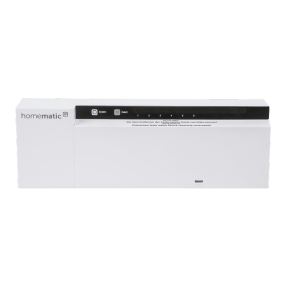
Lieferumfang Anzahl Bezeichnung Homematic IP Wired Fußbodenheizungs- aktor – 6-fach, 230 V Schrauben 4,0 x 40 mm Dübel 6 mm Bedienungsanleitung Dokumentation © 2018 eQ-3 AG, Deutschland Alle Rechte vorbehalten. Ohne schriftliche Zustimmung des Herausgebers darf diese Anleitung auch nicht auszugsweise in... - Seite 6 Selecttaste drücken press select button Systemtaste drücken press system button...
-
Seite 7: Inhaltsverzeichnis
............24 6.5.2 Einen weiteren Fußbodenheizungsaktor hinzu- fügen................. 25 6.5.3 Anlernen an die Zentrale CCU3 ......26 6.5.4 Anlernen an die Homematic IP Cloud per Wired Access Point ............28 Konfiguration über den Homematic IP Wired Wand- thermostaten..............30 Manuelle Bedienung ............39... - Seite 8 Geräteverknüpfungen löschen ........41 10 Fehlercodes und Blinkfolgen ........42 10.1 Blinkfolgen der System-LED (A)........42 10.2 Blinkfolgen der Kanal-LED (B) .......... 43 Wiederherstellung der Werkseinstellungen ..... 44 12 Wartung und Reinigung ..........44 13 Technische Daten ............45...
-
Seite 9: Hinweise Zur Anleitung
Hinweise zur Anleitung Hinweise zur Anleitung Lesen Sie diese Anleitung sorgfältig, bevor Sie Ihr Home- matic IP Wired Gerät in Betrieb nehmen. Bewahren Sie die Anleitung zum späteren Nachschlagen auf! Wenn Sie das Gerät anderen Personen zur Nutzung über- lassen, übergeben Sie auch diese Anleitung. Benutzte Symbole: Achtung! Hier wird auf eine Gefahr hingewiesen. - Seite 10 Gefahrenhinweise ausweist. Lassen Sie das Gerät im Zweifelsfall von einer Fachkraft prüfen. Betreiben Sie das Gerät nur in trockener sowie staubfreier Umgebung, setzen Sie es keinem Ein- fluss von Feuchtigkeit, Vibrationen, ständiger Sonnen- oder anderer Wärmeeinstrahlung, Kälte und keinen mechanischen Belastungen aus. Das Gerät ist kein Spielzeug! Erlauben Sie Kindern nicht damit zu spielen.
- Seite 11 Gefahrenhinweise (nach VDE 0100) erfolgen. Dabei sind die gelten- den Unfallverhütungsvorschriften zu beachten. Zur Vermeidung eines elektrischen Schlages am Gerät, schalten Sie bitte die Netzspannung frei (Si- cherungsautomat abschalten). Bei Nichtbeach- tung der Installationshinweise können Brand oder andere Gefahren entstehen. SELV/PELV-Stromkreise dürfen nicht an die Schalt- ausgänge angeschlossen werden.
- Seite 12 Gefahrenhinweise Der Netzstromkreis muss mit einem Leitungs- schutzschalter gemäß EN 60898-1 (Auslösecha- rakteristik B oder C, max. 6 A Nennstrom, min 6 KA Abschaltvermögen, Energiebegrenzungsklas- se 3) abgesichert sein. Das Gerät ist nicht zum Freischalten geeignet. Eine Überlastung kann zur Zerstörung des Gerä- tes, zu einem Brand oder zu einem elektrischen Schlag führen.
-
Seite 13: Funktion Und Geräteübersicht
Mit dem Homematic IP Wired Fußbodenheizungsak- tor können Sie Ihre Fußbodenheizung Raum für Raum komfortabel und bedarfsgerecht per Smartphone App oder mit dem Homematic IP Wired Wandthermostaten steuern und so die Raumtemperatur auf Ihre individuellen Bedürfnisse anpassen. Der Fußbodenheizungsaktor kann zur Steuerung einer Fußbodenheizung mit bis zu 6 Heizzonen/9 Heizkreisen... -
Seite 14: Allgemeine Systeminformationen
Kabelführung 1 Kabelführung 2 Kabelführung 3 Allgemeine Systeminformationen Dieses Gerät ist Teil des Homematic IP Smart-Home- Systems und kommuniziert über das Homematic IP Pro- tokoll. Sie haben die Möglichkeit, alle Geräte des Systems komfortabel und individuell über die Bedienoberfläche der Zentrale CCU3 oder flexibel per Smartphone über die Homematic IP App in Verbindung mit der Homema-... -
Seite 15: Montage
Montage Montage Sie können den Fußbodenheizungsaktor mit den mitge- lieferten Schrauben frei an der Wand montieren oder auf eine Hutschiene setzen. Schraubmontage Um den Fußbodenheizungsaktor mithilfe der Schrauben zu montieren, gehen Sie wie folgt vor: • Wählen Sie einen geeigneten Montageort in der Nähe Ihres Heizkreisverteilers aus. -
Seite 16: Inbetriebnahme
Inbetriebnahme Installationshinweise Bevor Sie das Gerät installieren und in Betrieb nehmen können, müssen Sie zunächst einen Homematic IP Wired Access Point (HmIPW- DRAP) in Betrieb nehmen. Bitte notieren Sie sich vor der Installation die auf dem Gerät angebrachte Gerätenummer (SGTIN) und den Verwendungszweck, damit Sie das Gerät... - Seite 17 Inbetriebnahme • das Leben der Nutzer der elektrischen Anlage. Mit einer unsachgemäßen Installation riskieren Sie schwere Sachschäden, z. B. durch einen Brand. Es droht für Sie die persönliche Haftung bei Personen- und Sach- schäden. Wenden Sie sich an einen Elektroinstallateur! *Erforderliche Fachkenntnisse für die Installation: Für die Installation sind insbesondere folgende Fachkenntnisse er- forderlich:...
-
Seite 18: Kabeldurchmesser Und Leitungsquerschnitte
Inbetriebnahme Für den Einbau des Fußbodenheizungsaktos in einen Stromkreisverteiler, muss das Gerät ent- sprechend VDE 0603, DIN 43871 (Niederspan- nungsunterverteilung (NSUV)), DIN 18015-x ein- gebaut werden. In diesem Fall muss die Montage auf einer Tragschiene (Hutschiene, DIN-Rail) lt. EN50022 erfolgen. Installation und Verdrahtung sind entsprechend VDE 0100 (VDE 0100-410, VDE 0100-510 usw.) durchzuführen. -
Seite 19: Installation
Aderendhülse [mm 0,5 – 1,50 0,5 – 1,50 Aus Gründen der elektrischen Sicherheit darf zum Anschluss des Homematic IP Wired Bus aus- schließlich das mitgelieferte Homematic IP Wired Buskabel oder ein als Zubehör erhältliches eQ-3 Homematic IP Wired Buskabel anderer Länge verwendet werden. - Seite 20 • Schließen Sie den Homematic IP Wired Bus an den Busanschluss 1 (J) bzw. Busanschluss 2 (K) an. Der Bus wird vom Homematic IP Wired Ac- cess Point (HmIPW-DRAP) gespeist. Weitere In- formationen dazu können Sie der Bedienungsan- leitung des Wired Access Points entnehmen.
-
Seite 21: Verhalten Nach Einschalten Der Spannungsversorgung
Inbetriebnahme • Achten Sie vor dem Verschließen der Abdeckung darauf, dass alle Anschlussleitungen ordnungs- gemäß in die vorgesehenen Kabelführungen ge- drückt sind. • Schließen Sie die Abdeckung wieder, indem Sie die Rastnasen der Abdeckung in die vorgesehe- nen Öffnungen schieben und die Abdeckung he- runterdrücken. -
Seite 22: Anlernen
Inbetriebnahme nungsversorgung befindet sich der Fußbodenheizungs- aktor im Anlernmodus, sofern er noch nicht angelernt wurde. Weitere Informationen zum Anlernen finden Sie im nachfolgenden Abschnitt. In den ersten 10 Minuten nach dem Einschalten der Netzspannung befindet sich der Fußbodenheizungsak- tor im Startmodus. In dieser Zeit werden alle Heizzonen angesteuert. - Seite 23 Sie können den Fußbodenheizungsaktor direkt an den Wired Wandthermostaten (HmIPW-WTH) anlernen. Die Konfiguration erfolgt dann direkt über den Wandther- mostaten (s. „6.5.1 Anlernen an den Homematic IP Wired Wandthermostaten“ auf Seite 24). Anlernen an die Zentrale CCU3 Für eine lokale, softwarebasierte Konfiguration und Steu- erung per PC haben Sie die Möglichkeit, den Fußboden-...
-
Seite 24: Anlernen An Den Homematic Ip Wired Wand- Thermostaten
Inbetriebnahme 6.5.1 Anlernen an den Homematic IP Wired Wand- thermostaten Sie können den Anlernvorgang durch erneute kurze Betätigung der Systemtaste (A) abbrechen. Dies wird durch ein rotes Aufleuchten der LED (A) bestätigt. Wenn kein Anlernen erfolgt, wird der Anlernmo- dus automatisch nach 3 Minuten beendet. -
Seite 25: Einen Weiteren Fußbodenheizungsaktor Hinzu- Fügen
Geräte-LED (A) signalisiert. War der Anlern- vorgang nicht erfolgreich, leuchtet die LED (A) rot auf. Versuchen Sie es erneut. • Lernen Sie den neuen Fußbodenheizungsaktor ggf. an weitere Homematic IP Geräte, wie z. B. an einen Wandthermostaten, an, indem Sie zunächst... -
Seite 26: Anlernen An Die Zentrale Ccu3
Zentrale CCU3 anzulernen, gehen Sie wie folgt vor: • Richten Sie zunächst Ihre Zentrale CCU3 gemäß der zugehörigen Bedienungsanleitung ein und lernen Sie den Homematic IP Wired Access Point • Starten Sie die Benutzeroberfläche „Homematic WebUI“ auf Ihrem PC. •... - Seite 27 Inbetriebnahme Die Zentrale wird für 60 Sekunden in den Anlern- modus versetzt. Ein Infofeld zeigt die aktuell noch verbleibende Anlernzeit. Drücken Sie kurz auf die Systemtaste (A), bis die • LED langsam orange zu blinken beginnt (s. Abbil- dung 7). Der Anlernmodus für den ausgewählten Kanal ist für 3 Minuten aktiv.
-
Seite 28: Anlernen An Die Homematic Ip Cloud Per Wired
6.5.4 Anlernen an die Homematic IP Cloud per Wired Access Point Wenn Sie Ihre Homematic IP Wired Geräte flexibel per Smartphone-App steuern möchten, können Sie die Homematic IP Wired Geräte einfach an die Homematic IP Cloud anlernen. Gehen Sie dazu wie folgt vor: •... - Seite 29 Inbetriebnahme gemäß der zugehörigen Bedienungsanleitung über die Smartphone-App an die Homematic IP Cloud an. Wählen Sie den Menüpunkt „Gerät anlernen“ aus. • • Drücken Sie kurz auf die Systemtaste (A), bis die LED langsam orange zu blinken beginnt (s. Abbil- dung 7).
-
Seite 30: Konfiguration Über Den Homematic Ip Wired Wand- Thermostaten
• Vergeben Sie in der App einen Namen für das Ge- rät und ordnen Sie es einem Raum zu. Wenn Sie bereits Homematic IP Geräte im Smart- Home-System nutzen oder Ihre Wired Geräte mit Funk-Komponenten von Homematic IP kombi- nieren möchten, können Sie die Homematic IP Wired Geräte auch einfach an einen (bestehen-... - Seite 31 Konfiguration über den Homematic IP Wired Wandthermostaten Um den Fußbodenheizungsaktor über den Wandthermo- staten zu konfigurieren, gehen Sie wie folgt vor: • Drücken Sie lange auf das Stellrad des Wandther- mostaten, um das Konfigurationsmenü zu öffnen. • Wählen Sie durch Drehen des Stellrads das Sym- bol „...
- Seite 32 Konfiguration über den Homematic IP Wired Wandthermostaten Geräteparameter UnP1: Parameter Index Wert Bedeutung Frostschutz- P024 Frostschutz inaktiv temperatur 2,0 °C 2,5 °C 8,0 °C (default) 9,5 °C 10,0 °C...
- Seite 33 Konfiguration über den Homematic IP Wired Wandthermostaten Pumpensteu- P025 Pumpensteuerung erung aktiv aktiv/inaktiv, Lastausgleich NC Pumpensteuerung Lastausgleich aktiv Lastsamm- Lastausgleich NO lung Pumpensteuerung aktiv Antriebstyp Lastsammlung NC (NO/NC Pumpensteuerung aktiv Lastsammlung NO Pumpensteuerung inaktiv (default) Lastausgleich NC Pumpensteuerung inaktiv Lastausgleich NO...
- Seite 34 Konfiguration über den Homematic IP Wired Wandthermostaten Ventil PWM P026 Regelungswert im Notbetrieb … im Heizmodus 25 % (default) … 99 % 100 % 0 % (default) Ventil PWM Re- P032 gelungswert im Notbetrieb im … … Kühlmodus 99 % 100 % *1: Heizzonen werden (wenn möglich) gestaffelt gesteuert.
- Seite 35 Konfiguration über den Homematic IP Wired Wandthermostaten Geräteparameter UnP2: Parameter Index Wert Bedeutung Ventil- P007 0 Minuten schutz- 1 Minute Funktions- 5 Minuten (default) Dauer 10 Minuten Ventil- P051 0 Tage schutz- 1 Tag Funktions- 14 Tage (default) Intervallzeit 27 Tage...
- Seite 36 Konfiguration über den Homematic IP Wired Wandthermostaten Dauer/ P007 0 Minuten Länge der 1 Minute (default) Pumpen- schutzfunk- 9 Minuten tion (nur 10 Minuten für Kanal 1 verfügbar) Ausschalt- P008 0 Minuten verzöge- 1 Minute 2 Minuten (default) rung der Pumpe (nur für Kanal 1...
- Seite 37 Konfiguration über den Homematic IP Wired Wandthermostaten Luftfeuch- P050 40 %; Luftfeuchtig- tigkeits- keitsgrenze inaktiv grenze … … 80 %; Luftfeuchtig- keitsgrenze inaktiv 40 %; Luftfeuchtig- keitsgrenze aktiv … … 60 %; Luftfeuch- tigkeitsgrenze aktiv (default) … … 80 %; Luftfeuchtig-...
- Seite 38 Konfiguration über den Homematic IP Wired Wandthermostaten Heizen im P053 Heizen im Heiz- Heizmodus modus inaktiv Heizen im aktiv/inaktiv Heizmodus aktiv (default) Auswahl der P054 Standardraum (default) räumlichen Gegeben- Raum mit Kamin heiten Raum mit Hand- tuch-Heizung FBH Standard Auswahl der P055 häuslichen...
-
Seite 39: Manuelle Bedienung
Manuelle Bedienung Vor- Luft- P178 40 %; Luftfeuchtig- feuchtig- keitsgrenze inaktiv keitsgrenze … … 80 %; Luftfeuchtig- keitsgrenze inaktiv 40 %; Luftfeuchtig- keitsgrenze aktiv … … 60 %; Luftfeuch- tigkeitsgrenze aktiv (default) … … 80 %; Luftfeuchtig- keitsgrenze aktiv Weiterführende Informationen zur Konfiguration können Sie der Bedienungsanleitung des Home- matic IP Wandthermostaten (HmIP-WTH-2) ent- nehmen. -
Seite 40: Pumpensteuerung Aktivieren Bzw. Deaktivieren
Manuelle Bedienung Wählen Sie mit der Selecttaste (B) den gewünsch- • ten Kanal aus (s. Abbildung 7). • Drücken Sie die Selecttaste solange, bis die LED (B) dreimal kurz grün blinkt. Der Kanal bleibt für 15 Minuten ein- bzw. ausgeschaltet. Anschließend wird die Heizzone wieder normal geregelt. -
Seite 41: Geräteverknüpfungen Löschen
Geräteverknüpfungen löschen Geräteverknüpfungen löschen Um die Geräteverknüpfungen zwischen einem Fußbo- denheizungsaktor und einem Wandthermostaten zu lö- schen, gehen Sie wie folgt vor: • Wählen Sie über die Selecttaste (B) des Fußbo- denheizungsaktors den Kanal aus, an den der Wandthermostat angelernt ist (s. Abbildung 7). Drücken Sie die Systemtaste (A) und die Selecttas- •... -
Seite 42: Fehlercodes Und Blinkfolgen
Lernen Sie das Gerät ges Blinken aktiv gemäß Abschnitt (alle 10 s) „6.5 Anlernen“ auf Seite 22 an einen Homematic IP Wired Access Point oder direkt an ein Homematic IP Wired Gerät an. 1x langes Vorgang be- Sie können mit der grünes... -
Seite 43: Blinkfolgen Der Kanal-Led (B)
Fehlercodes und Blinkfolgen 6x langes Gerät defekt Achten Sie auf die rotes Blinken Anzeige in Ihrer App oder wenden Sie sich an Ihren Fachhändler. 1x oranges Testanzeige Nachdem die Test- und 1x grünes anzeige erloschen Leuchten ist, können Sie fortfahren. 10.2 Blinkfolgen der Kanal-LED (B) Blinkcode... -
Seite 44: Wiederherstellung Der Werkseinstellungen
Lassen Sie die Systemtaste wieder los, um das Wiederherstellen der Werkseinstellungen abzu- schließen. Das Gerät führt einen Neustart durch. Nach dem Neustart können Sie das Gerät wieder in Ihr Homematic IP System integrieren. Wartung und Reinigung Das Gerät ist wartungsfrei. Überlassen Sie eine Re-... -
Seite 45: Technische Daten
Reinigen Sie das Gerät mit einem weichen, sauberen, trockenen und fusselfreien Tuch. Verwenden Sie keine lösemittelhaltigen Reinigungsmittel, das Kunststoffge- häuse und die Beschriftung können dadurch angegriffen werden. Technische Daten Geräte-Kurzbezeichnung: HmIPW-FAL230-C6 Versorgungsspannung: 24 V , ±5 %, SELV Stromaufnahme: 80 mA max. Konstruktion des Regel- und Steuergerätes (RS):... - Seite 46 Technische Daten Schaltleistung je Heizzone (Antrieb): 1 A max. Nennlast aller Antriebe: 230 W max. Art der Abschaltung: µ-Kontakt Schaltspiele: 20.000 (HZ1); 200.000 (HZ2-HZ10) Leitungsart u. -querschnitt: starre und flexible Leitung, 0,5 - 1,5 mm² Kabeldurchmesser Klemmanschluss 1: > 5,2 mm Kabeldurchmesser Klemmanschluss 2: >...
- Seite 47 Technische Daten Entsorgungshinweis Gerät nicht im Hausmüll entsorgen! Elektroni- sche Geräte sind entsprechend der Richtlinie über Elektro- und Elektronik-Altgeräte über die örtlichen Sammelstellen für Elektronik-Altgeräte zu entsorgen. Konformitätshinweis Das CE-Zeichen ist ein Freiverkehrszeichen, das sich ausschließlich an die Behörden wendet und keine Zusicherung von Eigenschaften beinhaltet.
-
Seite 48: Package Contents
Package contents Quantity Description Homematic IP Wired Floor Heating Actuator – 6 channels, 230 V Screws 4.0 x 40 mm Plugs 6 mm User manual Documentation © 2018 eQ-3 AG, Germany. All rights reserved. Translation from the original version in Ger- man. - Seite 49 Wired Wall Thermostat ......... 65 6.6.2 Adding a new floor heating actuator ....66 6.6.3 Connecting to the CCU3 ........67 6.6.4 Connecting to the Homematic IP cloud via Wired Access Point ..........70 Configuration via the Wired Wall Thermostat ..71 Manual operation ............79...
- Seite 50 10.1 Flashing sequences of the system LED (A) .....81 10.2 Flashing sequences of the channel LED (B) ....82 Restore factory settings ..........83 12 Maintenance and cleaning ...........83 13 Technical specifications ..........84...
-
Seite 51: Information About This Manual
Information about this manual Information about this manual Please read this manual carefully before beginning op- eration with your Homematic IP Wired component. Keep the manual so you can refer to it at a later date if you need to. - Seite 52 Hazard information Do not use the device if there are signs of dam- age to the housing, control elements or connect- ing sockets, for example. If you have any doubts, have the device checked by an expert. The device may only be operated in dry and dust- free environment and must be protected from the effects of moisture, vibrations, solar or other methods of heat radiation, cold and mechanical...
- Seite 53 Hazard information electricians (to VDE 0100) are permitted to carry out work on the 230 V mains. Applicable accident prevention regulations must be complied with whilst such work is being carried out. To avoid electric shocks from the device, please discon- nect the mains voltage (trip the miniature circuit- breaker).
- Seite 54 Hazard information The supply circuit has to be secured by a cable protection switch in accordance with EN 60898- 1 (tripping characteristic B or C, max. 6 A rated current, min. 6 KA interrupting rating, energy lim- iting class 3). The device has not been designed to support safety disconnection.
-
Seite 55: Function And Device Overview
Function and device overview Function and device overview The Homematic IP Wired Floor Heating Actuator offers comfortable and demand-based room-by-room control of your floor heating system via smartphone app or the Homematic IP Wired Wall Thermostat, according to your personal needs. -
Seite 56: General System Information
Cable bushing 3 General system information This device is part of the Homematic IP smart home system and works with the Homematic IP protocol. All devices of the system can be configured comfortably and individually with the user interface of the Central Control Unit CCU3 or flexibly via the Homematic ... -
Seite 57: Screw Mounting
Mounting Screw mounting For mounting the floor heating actuator using screws, please proceed as follows: • Please select a suitable mounting location close to your heating manifold. Make sure that no electricity or similar lines run in the wall at this location! •... -
Seite 58: Start-Up
Start-up Installation instructions Before installing and setting up the device, you have to put a Homematic IP Wired Access Point (HmIPW-DRAP) into operation first. Before installation, please note the device num- ber (SGTIN) labelled on the device as well as the exact application purpose in order to make later allocation easier. - Seite 59 Start-up The following specialist knowledge is particularly impor- tant during installation: • The “5 safety rules” to be used: Disconnect from mains; Safeguard from switching on again; Check that system is deenergised; Earth and short cir- cuit; Cover or cordon off neighbouring live parts; •...
-
Seite 60: Cable Diameter And Cable Cross-Sections
Start-up Please note the insulation stripping length of the conductor to be connected, indicated on the de- vice. Please observe the hazard information in section „2 Hazard information“ on page <?> during in- stallation. Cable diameter and cable cross-sections Permitted cable diameter for the cable bushings of the floor heating actuator are: Cable bushings Cable diameter... -
Seite 61: Installation
Start-up For electrical safety reasons, only the supplied Homematic IP Wired Bus Cable may be used for connecting the device to the Homematic IP Wired bus. Furthermore, an eQ-3 Homematic IP Wired Bus Cable with other lengths (available as accessory) can be used. - Seite 62 Start-up • Connect the phase conductor to connecting ter- minal L (G) . • Plug-in the connecting cables of the valve actua- tors into your heating circuits to the connect- ing terminals (H-I) or connect a heating pump using connecting terminal (H). •...
-
Seite 63: Behaviour After Switching On The Power Supply
Start-up Behaviour after switching on the power supply After switching on the mains voltage, the LED (B) lights permanently green. If the device has not yet been connected, teach-in mode will be activated during the first 3 minutes after the power has been supplied. -
Seite 64: Teaching-In
Direct pairing You can directly connect the floor heating actuator to the wired wall thermostat (HmIPW-WTH). The configu- ration is then directly carried via the wall thermostat (see „6.5.1 Pairing with a Homematic IP Wired Wall Thermostat“... -
Seite 65: Pairing With A Homematic Ip Wired Wall Thermostat
Connecting to the Homematic IP cloud For flexible control via the free smartphone app, you can connect the floor heating actuator to the Homematic IP cloud (see „6.5.4 Connecting to the Homematic IP cloud via Wired Access Point“ on page 70). You can •... -
Seite 66: Adding A New Floor Heating Actuator
3 seconds. If you want to pair the floor heating actuator with a Homematic IP Wired Wall Thermostat, the pairing mode of both devices has to be activated first. To do this, pro- ceed as follows: •... -
Seite 67: Connecting To The Ccu3
Start-up • First pair the new floor heating actuator with an existing one. Activate the pairing mode of the ex- isting floor heating actuator. Therefore, press and hold down the system button (A) for at least 4 seconds. • Activate the pairing mode of the new floor heating actuator. - Seite 68 Start-up Homematic IP Wired Access Point. • Start the user interface “Homematic WebUI” on your computer. • Click the “Teach-in devices” button on the right- hand side of the screen. • To activate teach-in mode, click “Teach-in HmIP device” in the next window. The teach-in mode of the Central Control Unit will be activated for 60 seconds.
- Seite 69 You will find fur- ther information in the Homematic IP Wired Installation Guide, available for download at www.eQ-3.com. For operation without Internet connection, please select the option “Teaching-in of Homematic IP de-...
-
Seite 70: Connecting To The Homematic Ip Cloud Via
6.6.4 Connecting to the Homematic IP cloud via Wired Access Point If you want to control your Homematic IP Wired devices flexibly via smartphone app, they can be connected to the Homematic IP cloud. To do this, please proceed as follows: •... -
Seite 71: Configuration Via The Wired Wall Thermostat
In the app, give the device a name and allocate it to a room. If you are already using Homematic IP devices in your smart home system or if you want to com- bine your Homematic IP Wired devices with wire-... - Seite 72 Configuration via the Wired Wall Thermostat To configure the floor heating actuator using the wall thermostat, please proceed as follows: • Press and hold down the control wheel of the wall thermostat to open the configuration menu. • Select the symbol by turning the control wheel and confirm by pressing the control wheel briefly.
- Seite 73 Configuration via the Wired Wall Thermostat Device parameter UnP1: Parameter Index Value Meaning Frost P024 Frost protection activated protection 2.0 °C tempera- 2.5 °C ture 8.0 °C (default) 9.5 °C 10.0 °C Pump P025 Pump control activated control Load balancing NC activated/ Pump control activated deactiva-...
- Seite 74 Configuration via the Wired Wall Thermostat Valve P026 PWM con- trol value … in the 25 % (default) emergen- … cy mode 99 % during 100 % heating mode 0 % (default) Valve P032 control … … value in 99 % the emer- 100 % gency...
- Seite 75 Configuration via the Wired Wall Thermostat Device parameter UnP2: Parameter Index Value Meaning Duration P007 0 minutes of valve 1 minute protection 5 minutes (default) function 10 minutes Invertal P051 0 days time for 1 day valve 14 days (default) protection function 27 days...
- Seite 76 Configuration via the Wired Wall Thermostat Duration P007 0 minutes of pump 1 minute (default) protection function 9 minutes (only for 10 minutes channel 1) Switch- P008 0 minutes off delay 1 minute 2 minutes (default) of pump (only for channel 1) 19 minutes 20 minutes...
- Seite 77 Configuration via the Wired Wall Thermostat Humidity P050 40 %: humidity limit limit deactivated … … 80 %: humidity limit deactivated 40 %: humidity limit activated … … 60 %: humidity limit activated (default) … … 80 %: humidity limit activated Time P051...
- Seite 78 Configuration via the Wired Wall Thermostat Cooling P052 Cooling in cooling in cooling mode deactivated Cooling in cool- mode ing mode activated (default) Heating P053 Heating in heating in heating mode deactivated mode Heating in heat- ing mode activated (default) Standard room (de- Configura- P054...
-
Seite 79: Manual Operation
80 %: humidity limit activated For further information regarding the configura- tion, please refer to the user manual of the Homematic IP Wall Thermostat (HmIP-WTH-2). Manual operation Switch heating zones on/off For installation and tests you can manually switch single heating zones on or off. -
Seite 80: Activating/Deactivating The Pump Control
Manual operation The channel will be switched on or off for 15 minutes. Afterwards, normal operation will be continued for the heating zone. Activating/deactivating the pump control If you want to use connection terminal (H) for control- ling a heating pump, the heating zone can be switched to pump control directly via the device. -
Seite 81: Delete Device Connections
Flashing code Meaning Solution Short orange Teach-in Connect the device flashing mode active in accordance to (every 10 s) sec. „6.5 Teaching- in“ on page 64 to a Homematic IP Wired Access Point or directly to a Homematic IP Wired device. -
Seite 82: Flashing Sequences Of The Channel Led (B)
Error codes and flashing sequences 1x long green Transmission You can continue lighting confirmed operation. 1x long red Transmission Please try again. lighting failed 6x long red Device Please see your app flashing defective for error message or contact your retailer. 1x orange Test display Once the test display... -
Seite 83: Restore Factory Settings
• Release the system button to finish the proce- dure. The device will perform a restart. After the restart, you can again integrate your device into your Homematic IP system. Maintenance and cleaning The product does not require any maintenance. -
Seite 84: Technical Specifications
Clean the device using a soft, lint-free cloth that is clean and dry. Do not use any detergents containing solvents, as they could corrode the plastic housing and label. Technical specifications Device short name: HmIPW-FAL230-C6 Supply voltage: 24 V , +5 %, SELV Current consumption: 80 mA max. - Seite 85 Technical specifications 200,000 (HZ2-HZ10) Cable type and cross section: rigid and flexible cable, 0.5 - 1.5 mm² Cable diameter of cable bushing 1: > 5.2 mm Cable diameter of cable bushing 2: > 8.2 mm Cable diameter of cable bushing 3: >...
- Seite 86 Technical specifications Instructions for disposal Do not dispose of the device with regular domes- tic waste! Electronic equipment must be dis- posed of at local collection points for waste elec- tronic equipment in compliance with the Waste Electrical and Electronic Equipment Directive. Information about conformity The CE sign is a free trading sign addressed ex- clusively to the authorities and does not include...
- Seite 87 Kostenloser Download der Homematic IP App! Free download of the Homematic IP app! Bevollmächtigter des Herstellers: Manufacturer’s authorised representative: eQ-3 AG Maiburger Straße 29 26789 Leer / GERMANY www.eQ-3.de...