Inhaltsverzeichnis
Werbung
Verfügbare Sprachen
Verfügbare Sprachen
Werbung
Kapitel
Inhaltsverzeichnis

Verwandte Anleitungen für Rock Shox XLoc Full Sprint


Inhaltszusammenfassung für Rock Shox XLoc Full Sprint
- Seite 1 USER MANUAL 95-4318-002-000 Rev A © 2013 SRAM LLC...
-
Seite 2: Limitations Of Liability
SRAM LLC WARRANTY ExTENT of LiMiTEd WARRANTY Except as otherwise set forth herein, SRAM warrants its products to be free from defects in materials or workmanship for a period of two years after original purchase. This warranty only applies to the original owner and is not transferable. - Seite 3 This warranty does not apply when the product has been modified, including, but not limited to any attempt to open or repair any electronic and electronic related components, including the motor, controller, battery packs, wiring harnesses, switches, and chargers. This warranty does not apply when the serial number or production code has been deliberately altered, defaced or removed.
-
Seite 4: Inhaltsverzeichnis
TAbLE of CoNTENTS iNTRoduCTioN ���������������������������������������������������������������������������������������������������� 5 PARTS AND TOOLS .........................5 ANAToMY��������������������������������������������������������������������������������������������������������������� 6 xLoC fuLL SpRiNT™ iNSTALLATioN ��������������������������������������������������������������� 7 REMOvE THE XLOC(S) ........................7 INSTALL THE MMX™ COMPATIBLE SHIFTER (OPTIONAL) .......... 8 INSTALL THE REMOTE TO THE HANDLEBAR ..............9 INSTALL THE CONNECTAMAJIG™ TO THE REMOTE .............10 MEASURE AND CUT THE NEW HOSE ................... -
Seite 5: Safety Instructions
XLoc Full Sprint™ comes with the fork hose attached and bled. You do not need to bleed the front hose during installation. -
Seite 6: Anatomy
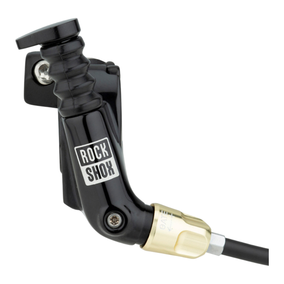
A n a t o m y A - Remote actuator I - Compression nut B - Remote bleed screw J - Hose barb C - Gate adjuster K - Compression fitting D - Fork hose L - Connectamajig E - Damper bleed screw M - Rear shock bleed screw F - Fork damper N - Rear shock banjo fitting... -
Seite 7: Xloc Full Sprint™ Installation
If your fork or rear shock has an XLoc, the XLoc(s) must be removed from the fork and/or rear shock prior to XLoc Full Sprint installation. R e m o v e t h e X L o c ( s ) Use a T25 TORX®... -
Seite 8: Install The Mmx™ Compatible Shifter (Optional)
I n s t a l l t h e M M X ™ C o m p a t i b l e S h i f t e r ( o p t i o n a l ) Insert the remote bracket nut in the channel of the remote clamp. -
Seite 9: Install The Remote To The Handlebar
I n s t a l l t h e R e m o t e t o t h e H a n d l e b a r Position the clamp block or XLoc™ compatible brake lever against the handlebar. Close the remote clamp around the handlebar and clamp block/brake lever. -
Seite 10: Install The Connectamajig™ To The Remote
I n s t a l l t h e C o n n e c t a m a j i g ™ t o t h e R e m o t e Inspect and clean the Connectamajig hose fitting threads and ball check valve. Push the hose fitting into the Connectamajig sleeve and turn the sleeve clockwise to thread the assembly together. -
Seite 11: Measure And Cut The New Hose
M e a s u r e a n d C u t t h e N e w H o s e Route the rear hose along or through the frame to the rear shock. Leave a gentle bend in the hose from the frame to the handlebar. -
Seite 12: Install The Hose To The Rear Shock
I n s t a l l t h e H o s e t o t h e R e a r S h o c k Push the hose into the shock banjo fitting until it stops. Slide the compression fitting and compression nut up to the banjo fitting. Turn the compression fitting clockwise to thread it into banjo fitting until it stops. -
Seite 13: Bleed Preparation
B l e e d P r e p a r a t i o n Check that the remote actuator is in the unlocked position. Turn the gate adjuster on the remote toward the “+” sign until it stops. Rotate the remote on the handlebar until the bleed screw is at the highest point. -
Seite 14: Bleed The Rear Hose
B l e e d t h e R e a r H o s e While holding both syringes upright, push on the rear shock syringe plunger and pull up on the remote syringe plunger at the same time. This will force fluid and any air bubbles through the hose and into the remote syringe. -
Seite 15: Remove The Fork Compression Damper
R e m o v e t h e F o r k C o m p r e s s i o n D a m p e r Depending on the fork, the compression damper removal procedure will vary . For detailed instructions on how to remove the compression damper, consult the service manual for your fork, available at sram.com/service. -
Seite 16: Final Adjustments
F i n a l A d j u s t m e n t s Spray isopropyl alcohol on the rear shock, rear hose, remote, front hose, and fork, and clean them with a rag. Rotate the remote to the desired position. Use a torque wrench with a T25 TORX® bit socket to tighten the remote clamp bolt to 5-6 N∙m (43-52 in-lb). - Seite 17 BEDIENUNGSANLEITUNG 95-4318-002-000 Rev A © 2013 SRAM LLC...
-
Seite 18: Lokale Gesetzgebung
GEWÄHRLEISTUNG DER SRAM LLC GARANTIEUMFANG Sofern in diesem Dokument nicht anders dargelegt, garantiert SRAM ab dem Erstkaufdatum für zwei Jahre, dass das Produkt frei von Herstellungs- und Materialfehlern ist. Diese Gewährleistung kann nur vom Erstkäufer in Anspruch genommen werden und ist nicht übertragbar. Ansprüche aus dieser Gewährleistung sind über den Händler, bei dem das Fahrrad oder die SRAM- Komponente erworben wurde, geltend zu machen. - Seite 19 Diese Garantie gilt nicht, wenn das Produkt modifiziert wurde, einschließlich, jedoch nicht beschränkt auf jeglichen Versuch, jegliche elektronischen und zugehörigen Komponenten zu öffnen oder zu reparieren, einschließlich Motoren, Steuerungen, Batterien, Kabelbäume, Schalter und Ladegeräte. Der Gewährleistungsanspruch erlischt ebenfalls, wenn die Seriennummer bzw. der Herstellungscode verändert, unkenntlich gemacht oder entfernt wurde.
- Seite 20 EiNLEiTuNG ����������������������������������������������������������������������������������������������������������21 KOMPONENTEN UND WERKZEUGE ..................21 AufbAu ���������������������������������������������������������������������������������������������������������������� 22 EiNbAu dES xLoC fuLL SpRiNT™ ������������������������������������������������������������������ 23 XLOC(S) AUSBAUEN ........................23 MMX™-KOMPATIBLEN SCHALTHEBEL EINBAUEN (OPTIONAL) ......24 FERNBEDIENUNG AM LENKER MONTIEREN ..............25 CONNECTAMAJIG™ AN DER FERNBEDIENUNG ANBRINGEN ........26 NEUE LEITUNG vERMESSEN UND KÜRZEN ..............27 LEITUNGSKLEMMRINGE INSTALLIEREN ................
-
Seite 21: Einleitung
Wartung von Fahrradkomponenten stets eine Schutzbrille und Nitrilhandschuhe zu tragen. E i n f ü h r u n g Das XLoc Full Sprint™-System wird mit montierter Gabelleitung und bereits entlüftet geliefert. Die vordere Leitung muss während des Einbaus nicht entlüftet werden. -
Seite 22: Aufbau
A u f b a u A - Fernbedienungseinsteller I - Überwurfmutter B - Fernbedienungs- J - Leitungsnippel Entlüftungsschraube K - Klemmring C - Gate-Einsteller L - Connectamajig D - Gabelleitung M - Dämpfer-Entlüftungsschraube E - Dämpfer-Entlüftungsschraube N - Dämpfer-Leitungsaufnahme F - Gabeldämpfer O - Leitungsmanschette G - Dämpferleitung... -
Seite 23: Einbau Des Xloc Full Sprint
Wenn Ihre Gabel oder Ihr Dämpfer mit einem XLoc versehen ist, müssen Sie den/die XLoc(s) von der Gabel und/oder vom Dämpfer abnehmen, bevor Sie den XLoc Full Sprint einbauen. X L o c ( s ) a u s b a u e n Lösen Sie mit einem T25 TORX®-Schlüssel die Klemmschraube vom hinteren XLoc. -
Seite 24: Mmx™-Kompatiblen Schalthebel Einbauen (Optional)
M M X ™ - k o m p a t i b l e n S c h a l t h e b e l e i n b a u e n ( o p t i o n a l ) Platzieren Sie die Mutter der Fernbedienungsklemmung im Kanal der Fernbedienungsklemmung. -
Seite 25: Fernbedienung Am Lenker Montieren
F e r n b e d i e n u n g a m L e n k e r m o n t i e r e n Positionieren Sie den Klemmblock oder einen XLoc-kompatiblen Bremshebel am Lenker. Schließen Sie die Fernbedienungsklemmung um den Lenker, sodass sie am Klemmblock/ Bremshebel anliegt. -
Seite 26: Connectamajig™ An Der Fernbedienung Anbringen
C o n n e c t a m a j i g ™ a m L e n k e r m o n t i e r e n Prüfen und reinigen Sie die Gewinde des Leitungsklemmrings des Connectamajig und das Kugelrückschlagventil. -
Seite 27: Neue Leitung Vermessen Und Kürzen
N e u e L e i t u n g v e r m e s s e n u n d k ü r z e n Führen Sie die hintere Leitung am Rahmen entlang oder durch den Rahmen zum Dämpfer. Belassen Sie in der Leitung einen leichten Bogen vom Lenker zum Rahmen. -
Seite 28: Leitung Am Dämpfer Anbringen
L e i t u n g a m D ä m p f e r a n b r i n g e n Schieben Sie die Leitung bis zum Anschlag in die Leitungsaufnahme am Dämpfer. Schieben Sie den Klemmring und die Überwurfmutter bis zur Leitungsaufnahme vor. Drehen Sie den Klemmring im Uhrzeigersinn, um ihn bis zum Anschlag in die Leitungsaufnahme zu schrauben. -
Seite 29: Vorbereiten Der Entlüftung
V o r b e r e i t e n d e r E n t l ü f t u n g Stellen Sie sicher, dass der Fernbedienungseinsteller entriegelt ist. Drehen Sie den Gate-Einsteller an der Fernbedienung bis zum Anschlag in Richtung des Pluszeichens (+). -
Seite 30: Hintere Leitung Entlüften
H i n t e r e L e i t u n g e n t l ü f t e n Während Sie beide Spritzen aufrecht halten, schieben Sie den Kolben der Spritze am Dämpfer vor und ziehen Sie gleichzeitig den Kolben der Spritze an der Fernbedienung etwas zurück. -
Seite 31: Gabel-Druckstufendämpfer Ausbauen
G a b e l - D r u c k s t u f e n d ä m p f e r a u s b a u e n Das verfahren für den Ausbau des Druckstufendämpfers ist je nach Gabel unterschiedlich. Ausführliche Anweisungen zum Ausbau des Druckstufendämpfers finden Sie in der Wartungsanleitung für Ihre Gabel unter sram.com/service. -
Seite 32: Abschliessende Einstellungen
A b s c h l i e ß e n d e E i n s t e l l u n g e n Sprühen Sie Isopropyl-Alkohol auf den Dämpfer, die hintere Leitung, die Fernbedienung, die vordere Leitung und die Gabel und säubern Sie die Komponenten mit einem Lappen. Drehen Sie die Fernbedienung in die gewünschte Position. - Seite 33 MANUAL DEL USUARIO 95-4318-002-000 Rev A © 2013 SRAM LLC...
-
Seite 34: Limitaciones De Responsabilidad
GARANTÍA DE SRAM LLC ALCANCE DE LA GARANTÍA LIMITADA Salvo indicación expresa en otro sentido, los productos SRAM están cubiertos por una garantía de dos años desde la fecha de compra original contra defectos de materiales o de fabricación. Esta garantía sólo se aplica al propietario original y no es transferible. - Seite 35 Esta garantía no cubre los daños que pueda sufrir el producto como consecuencia de accidentes, impactos, utilización indebida, incumplimiento de las especificaciones del fabricante o cualquier otra circunstancia en la que el producto haya sido sometido a fuerzas o cargas para las que no ha sido diseñado. Esta garantía no se aplicará...
-
Seite 36: Índice Temático
�������������������������������������������������������������������������������������������������� 37 PIEZAS Y HERRAMIENTAS ....................... 37 ANAToMÍA ����������������������������������������������������������������������������������������������������������� 38 iNSTALACiÓN dEL xLoC fuLL SpRiNT™ ������������������������������������������������������ 39 RETIRE LOS XLOC(S) ........................39 INSTALE LA PALANCA DE CAMBIO COMPATIBLE CON MMX™ (OPCIONAL) . 40 INSTALE EL CONTROL REMOTO EN EL MANILLAR ............41 INSTALE EL CONNECTAMAJIG™... -
Seite 37: Introducción
ó n XLoc Full Sprint™ viene con el manguito de la horquilla ya conectado y purgado. No es necesario purgar el manguito delantero durante la instalación. -
Seite 38: Anatomía
A n a t o m í a A – Actuador del control remoto I – Tuerca de compresión B – Tornillo de purgado del control remoto J – Conector de manguera C – Regulador de la compuerta K - Racor de compresión D –... -
Seite 39: Instalación Del Xloc Full Sprint
Si su horquilla o su amortiguador trasero llevan XLocs, deberá retirarlos de la horquilla y/o del amortiguador trasero antes de instalar el XLoc Full Sprint. R e t i r e l o s X L o c ( s ) Utilice una llave TORX®... -
Seite 40: Instale La Palanca De Cambio Compatible Con Mmx™ (Opcional)
Instale la palanca de cambio compatible con MMX™ (opcional) Instale la tuerca del soporte del control remoto en el canal correspondiente del control remoto. Coloque el soporte del control remoto en el lado exterior de la abrazadera MatchMaker X (MMX) e instale el tornillo del soporte MMX. Con una llave dinamométrica y una cazoleta T25 TORX®, apriete el tornillo del soporte con un par de entre 2,8 y 3,4 N∙m. -
Seite 41: Instale El Control Remoto En El Manillar
I n s t a l e e l c o n t r o l r e m o t o e n e l m a n i l l a r Coloque contra el manillar el bloque de abrazadera o la maneta de freno compatible con XLoc™. -
Seite 42: Instale El Connectamajig™ En El Control Remoto
I n s t a l e e l C o n n e c t a m a j i g ™ e n e l c o n t r o l r e m o t o Inspeccione y limpie las roscas del racor del manguito Connectamajig y la válvula de bola de comprobación. -
Seite 43: Instale Los Racores Del Manguito
M i d a y r e c o r t e e l n u e v o m a n g u i t o Haga llegar el manguito trasero hasta el amortiguador trasero a lo largo o a través del cuadro. - Seite 44 A c o p l e e l m a n g u i t o a l a m o r t i g u a d o r t r a s e r o Presione el manguito hasta el fondo para acoplarlo al racor banjo del amortiguador. Inserte el racor de compresión y la tuerca de compresión hasta llegar al racor banjo.
- Seite 45 P r e p a r a c i ó n p a r a e l p u r g a d o Asegúrese de que el actuador remoto se encuentre en la posición de desbloqueo. Gire a tope el regulador de la compuerta del control remoto en dirección hacia el signo “+”. Gire el control remoto en el manillar hasta que el tornillo de purgado quede en el punto más alto.
-
Seite 46: Purgado Del Manguito Trasero
P u r g a d o d e l m a n g u i t o t r a s e r o Sujetando ambas jeringuillas en posición vertical apuntando hacia arriba, presione el émbolo de la jeringuilla del amortiguador trasero y a la vez tire del émbolo de la jeringuilla del control remoto. -
Seite 47: Retire El Amortiguador De Compresión De La Horquilla
R e t i r e e l a m o r t i g u a d o r d e c o m p r e s i ó n d e l a h o r q u i l l a El procedimiento de desmontaje del amortiguador de compresión puede variar dependiendo de la horquilla. -
Seite 48: Ajustes Finales
A j u s t e s f i n a l e s Rocíe alcohol isopropílico sobre el amortiguador trasero, el manguito trasero, el control remoto, el manguito delantero y la horquilla, y límpielos con un trapo. Gire el control remoto hasta dejarlo en la posición que desee. Con una llave dinamométrica con cazoleta T25 TORX ®, apriete el tornillo de la abrazadera del control remoto con un par de entre 5 y 6 N∙m. - Seite 49 GUIDE DE L’UTILISATEUR 95-4318-002-000 Rev A © 2013 SRAM LLC...
-
Seite 50: Limites De Responsabilité
GARANTIE DE SRAM LLC DÉFINITION DE LA GARANTIE LIMITÉE Sauf indication contraire dans cette notice, SRAM garantit que ses produits ne présentent pas de défauts de matériaux ou de fabrication pour une durée de deux ans à partir de leur date d’achat originale. Cette garantie couvre uniquement le propriétaire d’origine et n’est pas transmissible. - Seite 51 La présente garantie ne s’applique pas lorsque le numéro de série ou le code de production a été intentionnellement altéré, rendu illisible ou supprimé. La présente garantie ne couvre pas les dommages résultant de l’usure normale. Les pièces d’usure subissent les dommages dus à...
- Seite 52 �������������������������������������������������������������������������������������������������� 53 COMPOSANTS ET OUTILS ......................53 piÈCES ������������������������������������������������������������������������������������������������������������������54 iNSTALLATioN du xLoC fuLL SpRiNT™ ������������������������������������������������������ 55 RETIRER LE(S) XLOC(S) ......................55 INSTALLER LA COMMANDE DU DÉRAILLEUR COMPATIBLE MMX™ (FACULTATIF) .56 INSTALLER LA COMMANDE À DISTANCE SUR LE CINTRE ........57 INSTALLER LE CONNECTAMAJIG™...
-
Seite 53: Consignes De Sécurité
Le XLoc Full Sprint™ est livré avec une durite pour la fourche déjà en place et purgée. Il n’est pas nécessaire de purger la durite située à l’avant. -
Seite 54: Pièces
p i è c e s A - Bouton sur la commande à distance I - Écrou de compression B - vis de purge de la commande à J - Raccord cannelé distance K - Olive de compression C - Molette de réglage de la compression L - Connectamajig D - Durite pour la fourche M - vis de purge de la suspension... -
Seite 55: Installation Du Xloc Full Sprint
Si votre fourche ou suspension arrière possède un XLoc, le(s) XLoc(s) doit(doivent) être retiré(s) de la fourche et/ou de la suspension arrière avant d’installer le XLoc Full Sprint. R e t i r e r l e ( s ) X L o c ( s ) À... -
Seite 56: Installer La Commande Du Dérailleur Compatible Mmx™ (Facultatif)
Installer la commande du dérailleur compatible MMX™ (facultatif) Insérez le contre-écrou du support de la commande à distance dans le trou du collier de la commande à distance. Placez le support de la commande à distance sur l’extérieur du collier du MatchMaker X™ (MMX) et mettez en place le boulon du support du MMX. À... -
Seite 57: Installer La Commande À Distance Sur Le Cintre
I n s t a l l e r l a c o m m a n d e à d i s t a n c e s u r l e c i n t r e Mettez en place la cale de fermeture du collier ou le levier de frein compatible XLoc™ contre le cintre. -
Seite 58: Installer Le Connectamajig™ Sur La Commande À Distance
I n s t a l l e r l e C o n n e c t a m a j i g ™ s u r l a c o m m a n d e à d i s t a n c e vérifiez et nettoyez le filetage du Connectamajig ainsi que le clapet anti-retour à... -
Seite 59: Mesurer Et Couper La Nouvelle Durite
M e s u r e r e t c o u p e r l a n o u v e l l e d u r i t e Faites cheminer la durite arrière jusqu’à la suspension arrière, le long du cadre ou à l’intérieur de celui-ci. -
Seite 60: Installer La Durite Sur La Suspension Arrière
I n s t a l l e r l a d u r i t e s u r l a s u s p e n s i o n a r r i è r e Enfoncez fermement la durite dans l’olive creuse de la suspension arrière jusqu’à ce qu’elle arrive en butée. -
Seite 61: Préparation De La Purge
P r é p a r a t i o n d e l a p u r g e Assurez-vous que la commande à distance est en position déverrouillée. Sur la commande à distance, tournez la molette de réglage de la compression en direction du signe «... -
Seite 62: Purger La Durite Arrière
P u r g e r l a d u r i t e a r r i è r e Maintenez les deux seringues avec l’embout orienté vers le haut, puis poussez sur le piston de la seringue de la suspension arrière tout en tirant en même temps sur le piston de la seringue de la commande à... -
Seite 63: Retirer L'amortisseur De Compression De La Fourche
R e t i r e r l ’ a m o r t i s s e u r d e c o m p r e s s i o n d e l a f o u r c h e Suivant le modèle de votre fourche, la procédure de démontage de l’amortisseur de compression peut varier. -
Seite 64: Derniers Réglages
D e r n i e r s r é g l a g e s vaporisez de l’alcool isopropylique sur la suspension arrière, la durite arrière, la commande à distance, la durite avant et la fourche puis nettoyez le tout à l’aide d’un chiffon. Inclinez la commande à... - Seite 65 MANUALE PER L’UTENTE Derniers réglages 95-4318-002-000 Rev A © 2013 SRAM LLC...
-
Seite 66: Limitazioni Della Garanzia
GARANZIA DI SRAM LLC PORTATA DELLA GARANZIA LIMITATA Tranne se diversamente stabilito di seguito, SRAM garantisce i propri prodotti per un periodo di due anni dalla data originale di acquisto per ogni difetto di materiali o di lavorazione. La presente garanzia si applica esclusivamente al proprietario originario e non è... - Seite 67 La presente garanzia non si applica nel caso che il prodotto sia stato modificato, compresi tra l’altro eventuali tentativi di aprire o riparare componenti elettronici o ad essi collegati, quali motore, controller, pacchi batteria, cablaggi, interruttori e caricatori. La presente garanzia non si applica nel caso che il numero di serie o il codice di produzione siano stati deliberatamente modificati, cancellati o rimossi.
- Seite 68 SoMMARio iNTRoduzioNE ��������������������������������������������������������������������������������������������������69 PARTI E STRUMENTI ........................69 ANAToMiA �����������������������������������������������������������������������������������������������������������70 iNSTALLAzioNE di xLoC fuLL SpRiNT™ ������������������������������������������������������71 RIMOZIONE DEGLI XLOC ......................71 INSTALLAZIONE DEL CAMBIO COMPATIBILE MMX™ (OPZIONALE) ....72 INSTALLAZIONE DEL GRUPPO REMOTO SUL MANUBRIO ........73 INSTALLAZIONE DEL CONNECTAMAJIG™ SUL GRUPPO REMOTO ...... 74 MISURAZIONE E TAGLIO DEL NUOvO TUBO ..............
-
Seite 69: Introduzione
XLoc Full Sprint™ è fornito col tubo della forcella collegato e spurgato. Non è necessario spurgare il tubo anteriore durante l’installazione. -
Seite 70: Anatomia
A n a t o m i a A - Attuatore remoto I - Dado di compressione B - vite di spurgo remota J - Stelo del tubo C - Regolatore Gate K - Raccordo di compressione D - Tubo per forcella L - Connectamajig E - vite di spurgo per smorzatore M - vite di spurgo per... -
Seite 71: Installazione Di Xloc Full Sprint
Se la forcella o l’ammortizzatore posteriore hanno un XLoc, gli XLoc devono essere rimossi dalla forcella e/o dall’ammortizzatore posteriore prima dell’installazione di XLoc Full Sprint. R i m o z i o n e d e g l i X L o c Utilizzare una chiave T25 TORX®... -
Seite 72: Installazione Del Cambio Compatibile Mmx™ (Opzionale)
I n s t a l l a z i o n e d e l c a m b i o c o m p a t i b i l e M M X ™ ( o p z i o n a l e ) Inserire il dado della staffa remota nel canale del morsetto remoto. -
Seite 73: Installazione Del Gruppo Remoto Sul Manubrio
I n s t a l l a z i o n e d e l g r u p p o r e m o t o s u l m a n u b r i o Posizionare il blocco del morsetto o la leva del freno compatibile con XLoc™ contro il manubrio. -
Seite 74: Installazione Del Connectamajig™ Sul Gruppo Remoto
I n s t a l l a z i o n e d e l C o n n e c t a m a j i g ™ s u l g r u p p o r e m o t o Esaminare e pulire le filettature del raccordo del tubo Connectamajig e la valvola di ritegno a sfera. -
Seite 75: Misurazione E Taglio Del Nuovo Tubo
M i s u r a z i o n e e t a g l i o d e l n u o v o t u b o Instradare il tubo posteriore lungo o attraverso il telaio verso l’ammortizzatore posteriore. Lasciare una curva delicata nel tubo dal telaio al manubrio. -
Seite 76: Installazione Del Tubo Sull'ammortizzatore Posteriore
I n s t a l l a z i o n e d e l t u b o s u l l ’ a m m o r t i z z a t o r e p o s t e r i o r e Premere il tubo nel raccordo banjo dell’ammortizzatore fino a quando si arresta. -
Seite 77: Preparazione Allo Spurgo
P r e p a r a z i o n e a l l o s p u r g o verificare che l’attuatore a distanza sia in posizione sbloccata. Ruotare il regolatore gate sul remoto verso il segno “+” fino a quando si arresta. Ruotare il remoto sul manubrio fino a quando la vite di spurgo si trovi nel punto più... -
Seite 78: Spurgo Del Tubo Posteriore
S p u r g o d e l t u b o p o s t e r i o r e Tenendo entrambe le siringhe in posizione verticale, spingere il pistone della siringa dell’ammortizzatore posteriore e tirare verso l’alto il pistone della siringa del remoto. Ciò spingerà... -
Seite 79: Rimozione Dello Smorzatore Di Compressione Della Forcella
R i m oz i o n e d e l l o s m o r z a t o r e d i c o m p r e s s i o n e d e l l a f o r c e l l a A seconda della forcella, la procedura di rimozione dello smorzatore di compressione varierà. -
Seite 80: Regolazioni Finali
R e g o l a z i o n i f i n a l i Spruzzare alcool isopropilico sull’ammortizzatore posteriore, sul tubo posteriore, sul remoto, sul tubo anteriore, sulla forcella e pulirli con uno straccio. Ruotare il remoto fino alla posizione desiderata. Utilizzare una chiave torsiometrica con un tubo per vite T25 TORX®... - Seite 81 GEBRUIKERSHANDLEIDING 95-4318-002-000 Rev A © 2013 SRAM LLC...
-
Seite 82: Beperkte Aansprakelijkheid
SRAM LLC GARANTIE REIKWIJDTE BEPERKTE GARANTIE Tenzij anders aangegeven in deze handleiding, garandeert SRAM zijn producten voor een periode van twee jaar na de oorspronkelijke aankoopdatum vrij van defecten in materialen of vakmanschap. Deze garantie is alleen van toepassing op de oorspronkelijke eigenaar en is niet overdraagbaar. - Seite 83 Deze garantie is niet van toepassing wanneer het serienummer of de productiecode opzettelijk is gewijzigd, beschadigd of verwijderd. Deze garantie is niet van toepassing op normale slijtage. Onderdelen die onderhevig zijn aan slijtage ondervinden schade als gevolg van normaal gebruik, het achterwege blijven van onderhoud volgens SRAM aanbevelingen en/of rijden of installeren onder omstandigheden anders dan aanbevolen.
- Seite 84 ������������������������������������������������������������������������������������������������������������ 85 ONDERDELEN EN GEREEDSCHAP ..................85 ANAToMiE �����������������������������������������������������������������������������������������������������������86 xLoC fuLL SpRiNT™ iNSTALLEREN ��������������������������������������������������������������� 87 DE XLOC(S) vERWIJDEREN ....................87 DE MMX™ COMPATIBELE SHIFTER INSTALLEREN (OPTIONEEL) ......88 DE AFZONDERLIJKE ASSEMBLAGE OP HET STUUR INSTALLEREN ....89 DE CONNECTAMAJIG™ OP DE AFZONDERLIJKE ASSEMBLAGE INSTALLEREN ..90 DE NIEUWE SLANG METEN EN KNIPPEN ................91...
-
Seite 85: Inleiding
XLoc Full Sprint™ komt met een bevestigde en ontluchte vorkslang. Tijdens het installeren is het niet nodig om de voorste slang te ontluchten. -
Seite 86: Anatomie
o n d e r d e l e n A - Aandrijver voor afzonderlijke assemblage I - Klemmoer B - Ontluchtingsschroef voor afzonderlijke J - Slangpilaar assemblage K - Klemfitting C - Overloopafsteller L - Connectamajig D - vorkslang M - Ontluchtingsschroef voor E - Ontluchtingsschroef voor schokdemper achterschokdemper... -
Seite 87: Xloc Full Sprint™ Installeren
Als uw vork of achterschokdemper van een XLoc voorzien is, verwijder de XLoc(s) van de vork en/of achterschokdemper voordat u de XLoc Full Sprint installeert. D e X L o c ( s ) v e r w i j d e r e n Maak de klembout van de achterste XLoc los met gebruik van een T25 TORX®... -
Seite 88: De Mmx™ Compatibele Shifter Installeren (Optioneel)
D e M M X ™ c o m p a t i b e l e s h i f t e r i n s t a l l e r e n ( o p t i o n e e l ) Installeer de moer van de afzonderlijke beugel in het kanaal van de afzonderlijke klem. -
Seite 89: De Afzonderlijke Assemblage Op Het Stuur Installeren
D e a f z o n d e r l i j k e a s s e m b l a g e o p h e t s t u u r i n s t a l l e r e n Plaats de klemblokkering of XLoc™... -
Seite 90: De Connectamajig™ Op De Afzonderlijke Assemblage Installeren
De Connectamajig™ op de afzonderlijke assemblage installeren Inspecteer en reinig de draad en de balfafsluiter van de Connectamajig-slangfitting. Duw de slangfitting in de Connectamajig-mof en draai de mof met de klok mee om de assemblage ineen te schroeven. Blijf de getande mof draaien totdat deze stopt. Gebruik een 6 mm steeksleutel om de slangfitting vast te houden en gebruik vervolgens een momentsleutel met een 9 mm kraaienpoot om de assemblage tot 1,2-2,8 N∙m aan te draaien. -
Seite 91: De Nieuwe Slang Meten En Knippen
D e n i e u w e s l a n g m e t e n e n k n i p p e n Leid de achterste slang langs of door het frame naar de achterschokdemper. Maak een flauwe bocht in de slang vanaf het frame naar het stuur. -
Seite 92: De Slang Op De Achterschokdemper Installeren
D e s l a n g o p d e a c h t e r s c h o k d e m p e r i n s t a l l e r e n Duw de slang in het banjoaansluitstuk van de schokdemper totdat deze stopt. Schuif de klemfitting en klemmoer op het banjoaansluitstuk. -
Seite 93: De Ontluchting Voorbereiden
D e o n t l u c h t i n g v o o r b e r e i d e n Controleer of de aandrijver van de afzonderlijke assemblage in de open positie staat. Draai de overloopafsteller op de afzonderlijke assemblage naar het “+” teken totdat deze stopt. Draai de afzonderlijke assemblage op het stuur totdat de ontluchtingsschroef zich op het hoogste punt bevindt. -
Seite 94: De Achterste Slang Ontluchten
D e a c h t e r s t e s l a n g o n t l u c h t e n Terwijl u beide spuiten rechtop houdt, duw op de plunjer van de spuit voor de achterschokdemper en trek de plunjer van de spuit voor de afzonderlijke assemblage tegelijkertijd uit. -
Seite 95: De Vorkcompressiedemper Verwijderen
D e v o r k c o m p r e s s i e d e m p e r v e r w i j d e r e n De verwijderingsprocedure van de compressiedemper verschilt naar gelang de vork. voor gedetailleerde aanwijzingen over hoe de compressiedemper te verwijderen, raadpleeg de onderhoudshandleiding van uw vork, te vinden op sram.com/service. -
Seite 96: Laatste Afstellingen
L a a t s t e a f s t e l l i n g e n Spuit isopropylalcohol op de achterschokdemper, achterste slang, afzonderlijke assemblage, voorste slang en vork, en reinig deze met een doek. Draai de afzonderlijke assemblage naar de gewenste positie. Gebruik een momentsleutel met een T25 TORX®... - Seite 97 MANUAL DO UTILIZADOR 95-4318-002-000 Rev A © 2013 SRAM LLC...
-
Seite 98: Limitações Da Garantia
GARANTIA DA SRAM LLC ÂMBITO DA GARANTIA LIMITADA Excepto quando aqui se declare algo diferente, a SRAM garante os seus produtos quanto à não existência de defeitos de material nem de mão de obra, por um período de dois anos a contar da data da compra original. Esta garantia só se aplica ao dono original e não pode ser transferida. - Seite 99 Esta garantia não se aplica quando o produto tiver sido modificado, incluindo, mas sem ser limitado a qualquer tentativa de abrir ou reparar quaisquer componentes electrónicos ou relacionados com a electrónica, incluindo o motor, controlador, conjuntos de baterias, conjunto de cabos, interruptores e carregadores. Esta garantia não se aplica quando o número de série ou o código de produção tiverem sido deliberadamente alterados, obliterados ou removidos.
- Seite 100 ÍNdiCE iNTRoduÇÃo ����������������������������������������������������������������������������������������������������� 117 PEÇAS E FERRAMENTAS......................117 ANAToMiA ���������������������������������������������������������������������������������������������������������� 118 iNSTALAÇÃo do xLoC fuLL SpRiNT™ �������������������������������������������������������� 119 RETIRAR O(S) XLOC(S) ......................119 INSTALAR O MANÍPULO DE MUDANÇAS COMPATÍvEL COM O MMX™ (OPCIONAL) ...120 INSTALAR O CONJUNTO REMOTO NO GUIADOR ............121 INSTALAR O CONNECTAMAJIG™...
-
Seite 101: Introdução
ç ã o O XLoc Full Sprint™ é fornecido com o tubo flexível do garfo montado e sangrado. Não precisa de sangrar o tubo flexível da frente durante a instalação. -
Seite 102: Anatomia
A n a t o m i a A - Actuador remoto I - Porca de compressão B - Parafuso de sangrar do J - Miolo da união do tubo flexível dispositivo remoto K - União de compressão C - Regulador da válvula L - Connectamajig D - Tubo flexível do garfo M - Parafuso de sangrar o... -
Seite 103: Instalação Do Xloc Full Sprint
Se o seu garfo ou amortecedor traseiro tiver um XLoc, o(s) XLoc(s) tem que ser retirado(s) do garfo e/ou do amortecedor traseiro antes da instalação do XLoc Full Sprint. R e t i r a r o ( s ) X L o c ( s ) Use uma chave TORX®... -
Seite 104: Instalar O Manípulo De Mudanças Compatível Com O Mmx™ (Opcional)
Instalar o manípulo de mudanças compatível com o MMX™ (opcional) Insira a porca do suporte do dispositivo remoto no canal da braçadeira de aperto do dispositivo remoto. Posicione o suporte do dispositivo remoto no lado de fora da braçadeira de aperto do MatchMaker X™ (MMX) e instale o perno do suporte do MMX. Use uma chave dinamométrica com uma chave de caixa TORX®... - Seite 105 I n s t a l a r o d i s p o s i t i v o r e m o t o n o g u i a d o r Posicione o bloco da braçadeira de aperto ou a alavanca de travão compatível com o XLoc™...
-
Seite 106: Instalar O Connectamajig™ No Dispositivo Remoto
I n s t a l a r o C o n n e c t a m a j i g ™ n o d i s p o s i t i v o r e m o t o Inspeccione e limpe os fios de rosca da união ao tubo flexível e a válvula de retenção de bola do Connectamajig. -
Seite 107: Medir E Cortar O Novo Tubo Flexível
M e d i r e c o r t a r o n o v o t u b o f l e x í v e l Encaminhe o tubo flexível traseiro ao longo do quadro e através dele, até ao amortecedor traseiro. -
Seite 108: Instalar O Tubo Flexível No Amortecedor Traseiro
I n s t a l a r o t u b o f l e x í v e l n o a m o r t e c e d o r t r a s e i r o Empurre o tubo flexível para dentro da união terminal oca banjo do amortecedor até... -
Seite 109: Preparar Para Sangrar
P r e p a r a r p a r a s a n g r a r Certifique-se de que o actuador do dispositivo remoto esteja na posição de destrancado. Rode o regulador da válvula no dispositivo remoto para o lado do sinal “+” até que pare. Rode o dispositivo remoto no guiador até... -
Seite 110: Sangrar O Tubo Flexível Traseiro
S a n g r a r o t u b o f l e x í v e l t r a s e i r o Enquanto segura as duas seringas verticalmente, simultaneamente empurre o êmbolo da seringa do amortecedor traseiro e puxe para cima o êmbolo da seringa do conjunto remoto. Isto vai forçar fluido e quaisquer bolhas de ar através do tubo flexível e para dentro da seringa do dispositivo remoto. -
Seite 111: Retirar O Amortecedor De Compressão Do Garfo
R e t i r a r o a m o r t e c e d o r d e c o m p r e s s ã o d o g a r f o Dependendo do garfo, o procedimento para retirar o amortecedor de compressão irá variar. Para obter instruções detalhadas sobre como retirar o amortecedor de compressão, consulte o manual de serviço do seu garfo, disponível em sram.com/service. -
Seite 112: Ajustes Finais
A j u s t e s f i n a i s Borrife álcool isopropílico no amortecedor traseiro, tubo flexível traseiro, dispositivo remoto, tubo flexível da frente e garfo, e limpe-os com um trapo. Rode o dispositivo remoto para a posição desejada. Use uma chave dinamométrica com uma chave de caixa TORX®... - Seite 113 95-4318-002-000 Rev A © 2013 SRAM LLC...
- Seite 120 2.8-3.4 N·m 2.8-3.4 N·m...
- Seite 124 5 N·m...
- Seite 127 sram.com/service 7.3 N·m...
- Seite 129 95-4318-002-000 Rev A © 2013 SRAM LLC...
- Seite 136 2.8-3.4 N·m 2.8-3.4 N·m...
- Seite 140 5 N·m...
- Seite 143 sram.com/service 7.3 N·m...
- Seite 148 www.sram.com WORLD HEADQUARTERS ASIAN HEADQUARTERS EUROPEAN HEADQUARTERS SRAM LLC SRAM Taiwan SRAM Europe 1333 North Kingsbury, 4th floor No. 1598-8 Chung Shan Road Paasbosweg 14-16 Chicago, Illinois 60642 Shen Kang Hsiang, Taichung 3862 ZS Nijkerk County 429 ∙ Taiwan The Netherlands...