
Verwandte Anleitungen für Elektro-Automatik EA-PSI 800R


Inhaltszusammenfassung für Elektro-Automatik EA-PSI 800R
- Seite 1 Bedienungsanleitung Instruction Manual EA-PSI 800 R 1000W / 1500W PSI 880-40R : 21 540 407 PSI 880-60R : 21 540 408 PSI 8360-10R : 21 540 409 PSI 8360-15R : 21 540 410...
- Seite 3 Impressum Sicherheitshinweise Elektro-Automatik GmbH & Co. KG Helmholtzstrasse 31-33 • Der Querschnitt der Lastanschlußkabel muß für 41747 Viersen den maximalen Ausgangsstrom des jeweiligen Germany Gerätes ausgelegt sein! Telefon: 02162 / 37850 • Der Netzanschluss darf nur von entsprechendem Fax: 02162 / 16230 Fachpersonal ausgeführt werden!
-
Seite 4: Inhaltsverzeichnis
Reihenschaltung .......................... 16 Parallelschaltung ......................... 16 7. Sonstiges ............................17 Zubehör und Optionen ......................... 17 Firmwareaktualisierung ....................... 17 Ersatzableitstrommessung nach VDE 0701 ................17 © 2006, Elektro-Automatik GmbH & Co. KG Irrtümer und Änderungen vorbehalten Bedienungsanleitung Stand: 25.01.2016 PSI 800 R Serie... -
Seite 5: Allgemeines
Beschreibung Allgemeines Installation Einleitung Montage Das microcontrollergesteuerte Einbaunetzgerät der Das Gerät ist für die Wandmontage konzipiert und Serie PSI 800 R ist sowohl für den Festspannungs- so zu montieren, daß die Lüftungsein- und auslässe betrieb im normalen Industrieeinsatz als auch für sich in vertikaler Richtung befinden und mindestens einen variablen Spannungsbetrieb konzipiert. -
Seite 6: Anschluß Analoge Schnittstelle
Abkühlung des Gerätes erfolgen. In der Anzeige stelle oder eine optionale, nachrüstbare digitale wird während der bestehenden Übertemperatur die Schnittstellenkarte ferngesteuert werden. kommende, automatische Wiedereinschaltung des © 2006, Elektro-Automatik GmbH & Co. KG Ausgangs mit „auto ON“ angezeigt. Irrtümer und Änderungen vorbehalten Fernfühlung (Remote sense) -
Seite 7: Unterspannungsüberwachung
Beschreibung Unterspannungsüberwachung Konfigurierbare Spannungsprofile Die Überwachung der Unterspannung erfolgt über Es stehen mehrere vorkonfigurierte Spannungsprofi- zwei Unterspannungsschwellen. Die Überwachung le zur Verfügung, siehe die Tabellen unten. Das erste wird 250ms nach dem Einschalten des Leistungs- Spannungsprofil erlaubt die Einstellung von 0V bis ausgangs aktiv und reagiert immer erst nach >1s, zur Nennausgangsspannung. -
Seite 8: Technische Daten
Verschmutzungsgrad Betriebshöhe <2000m Analoge Programmierung Eingangsbereich 0…5V oder 0…10V, umschaltbar Genauigkeit © 2006, Elektro-Automatik GmbH & Co. KG <0.2% Irrtümer und Änderungen vorbehalten * Bezogen auf den jeweiligen Nennwert Alle Werte sind typische Werte Bedienungsanleitung Stand: 25.01.2016 PSI 800 R Serie... -
Seite 9: 3.10 Mechanische Zeichnungen
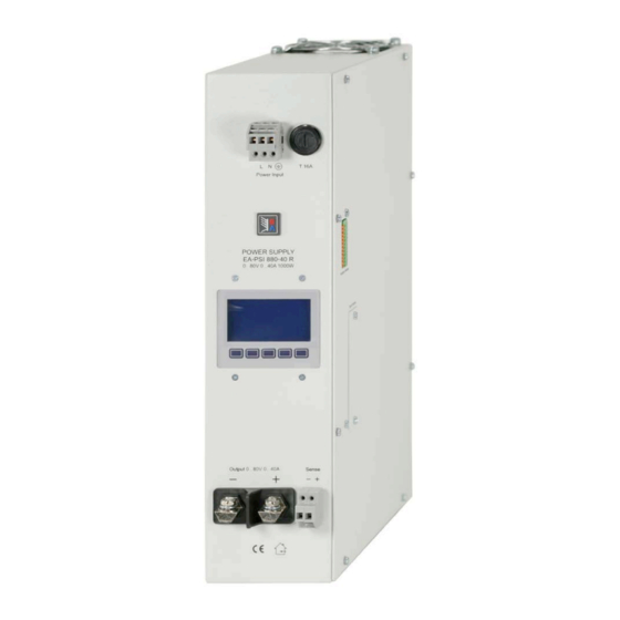
Beschreibung 3.10 Mechanische Zeichnungen Hinweis: Das Bild zeigt ein Gerät ohne eingebaute, digitale Schnittstelle. Bei Nutzung der analogen oder einer digitalen Schnittstelle ist rechts neben dem Gerät ausreichend Platz für Kabel vorzusehen. Bild 1. Vorderseite Bedienungsanleitung Stand: 25.01.2016 PSI 800 R Serie... - Seite 10 Beschreibung © 2006, Elektro-Automatik GmbH & Co. KG Irrtümer und Änderungen vorbehalten Bild 2. Ansicht von rechts mit analoger und dig. Schnittstelle Bedienungsanleitung Stand: 25.01.2016 PSI 800 R Serie...
-
Seite 11: Bedienung
Bedienung des Gerätes Bedienung Bedien- und Anzeigeeinheit 4.1.1 Aufteilung der Betriebsanzeige Spannungsprofil auswählen Die Anzeigeeinheit teilt sich auf in die Anzeige Hinweis: Wechsel des Spannungsprofil und Verän- derungen daran sind nur möglich bei Ausgang = aus! der Ausgangswerte, der Sollwerte, des Zustands des Leistungsausgangs und den Anzeigen der Nach Betätigung der Taste in der Betriebsan-... -
Seite 12: Bedienung Des Gerätes
Mit der Einstellung Power ON = OFF bleibt der Leistungs- ausgang des Netzgerätes ausgeschaltet. © 2006, Elektro-Automatik GmbH & Co. KG Irrtümer und Änderungen vorbehalten Zustand nach einer Übertemperaturabschaltung OT disappear (Voreinstellung: autoON) Sollte nach einer Übertemperaturabschaltung eine automatische Wiedereinschaltung des Leistungs- ausgangs gewünscht sein, muss die Einstellung auf... -
Seite 13: Analogue In/Out
Bedienung des Gerätes Hintergrundbeleuchtung Hinweis: analoge Fernsteuerung nur bei gewähltem Spannungsprofil 1. Ansonsten wird der Alarm Backlight (Voreinstellung: Delay 60s) gemeldet. Wenn Backlight = Delay 60s eingestellt wurde, wird die Hintergrundbeleuchtung des Displays nach dem Digital inputs Einschalten und nach jeder Betätigung einer Taste (Voreinstellung: LOW) für 60s eingeschaltet. -
Seite 14: Reset Configuration
Bei Fehlern, die den Ausgang tet ist, erscheint auf dem Display der Status „extern“. abschalten (OT, OVP) kann dieser nach dem Quit- © 2006, Elektro-Automatik GmbH & Co. KG Hinweis: die digitalen Eingänge sind keine CMOS-IC- tieren wieder eingeschaltet werden. -
Seite 15: Pinbelegung Und Technische Daten Der Analogen Schnittstelle
Bedienung des Gerätes 5.2.1 Pinbelegung und technische Daten der analogen Schnittstelle Name Bezeichnung Pegel Elektrische Eigenschaften 0….10V entspricht 0….100% U Genauigkeit < 0.2%, U = 12V VSEL AI Sollwert Spannung Nenn CSEL AI Sollwert Strom 0….10V entspricht 0….100% I Eingangsimpendanz >100k Nenn Genauigkeit <... -
Seite 16: Weitere Anwendungen
Achtung! Niemals Spannungen >12V an den Ein- Schnittstelle anzusprechen. Der Spannungs-Istwert gängen anlegen! © 2006, Elektro-Automatik GmbH & Co. KG gilt dann für alle Geräte in der Parallelschaltung. Der Irrtümer und Änderungen vorbehalten Sollwerte >10V bzw. 5V werden auf 100% Nennwert Strom-Istwert wird nicht automatisch summiert und gesetzt (Clipping). -
Seite 17: Sonstiges
Bedienung des Gerätes Sonstiges Grafische Verdeutlichung der symmetrischen Schaltung: Zubehör und Optionen Folgendes Zubehör ist erhältlich: a) Digitale Schnittstellenkarten Steck- und nachrüstbare Schnittstellenkarten für USB, RS232 oder CAN sind erhältlich. Details zu den Schnittstellenkarten siehe Schnittstellenkarten- handbuch. Es steht ein Steckplatz zur Verfügung. Netzeingang Beispieldarstellung aus der Norm, Bild C.3c, Schutzlei- Firmwareaktualisierung... -
Seite 19: Safety Instructions
About Elektro-Automatik GmbH & Co. KG Safety instructions Helmholtzstrasse 31-33 41747 Viersen • The cross section of the load leads has to match Germany the nominal current of the device! Phone: +49 2162 / 37850 • Avoid any damage to the device, do not insert met-... - Seite 20 Table of contents Page 1. General ............................... 21 Introduction ..........................21 Visual check ..........................21 Scope of delivery ......................... 21 2. Installation ............................21 Mounting ............................21 Mains connection ......................... 21 DC output connection ........................21 Analog interface connection ......................22 3.
-
Seite 21: About The Device
About the device General Installation Introduction Mounting The microprocessor controlled power supplies of the The device is designed for wall mount. It is required PSI 800 R series are designed for wall mount and to mount it in a way that allows unimpeded air flow work with fan cooling. -
Seite 22: Analog Interface Connection
About the device Analog interface connection Overvoltage protection (OVP) The 12 pole analog interface on the top side is of All models feature an overvoltage protection circuit type press & clamp. It is eligible for cable cross which is set 110% of the nominal output voltage. In sections of 0.1mm²... -
Seite 23: Undervoltage Supervision
Handling the device Undervoltage supervision Configurable voltage profiles The supervision of an undervoltage condition is done The device feature several voltage profiles that with two thresholds. It will be activated after 250ms are pre-configured for common applications. See and everytime the output is switched on. tables below. -
Seite 24: Handling The Device
Handling the device Technical specifications PSI 880-40R PSI 8360-10R PSI 880-60R PSI 8360-15R Mains input Input voltage 90….264V 90….264V 90….264V 90….264V Frequency 45….65Hz 45….65Hz 45….65Hz 45….65Hz Power factor correction >0.99 >0.99 >0.99 >0.99 Input current at 230V and full load approx. -
Seite 25: 3.10 Mechanical Drawings
Handling the device 3.10 Mechanical drawings Note: The figure shows a unit without digital interface equipped. When using the analog or digital interface, it is required to leave some space next to right side of the unit, for the cables. Figure 1. - Seite 26 Handling the device Figure 2. Side view from the right, with analog and dig..interface Instruction Manual Date: 01-25-2016 PSI 800 R Series...
-
Seite 27: Operation
Handling the device Operation Control and display panel 4.1.1 Layout of the display Selecting a voltage profile Note: Switching voltage profiles is only possible The display is separated into areas for set values, during output = off. actual values, the output state, device status and the button assignments. -
Seite 28: Editing A Voltage Profile
Handling the device If button is pushed instead, the selected profile Direct voltage adjustment is opened for adjustment. From the main display, the output voltage can also be directly accessed for adjustment by the Editing a voltage profile button. It jumps into the currently selected voltage The parameter that is going to be adjusted is se- profile and selects the voltage for adjustment. -
Seite 29: Display Illumination
Handling the device Display illumination Note: analog remote control is only possible with voltage profile 1 selected. Otherwise, the device will Backlight (default: Delay 60s) signalise alarm EXT. Backlight = Delay 60s is set, the backlight is gen- erally off and will be switched on for 60s after every Digital inputs (default: LOW) push of a button. -
Seite 30: Alarms
Handling the device 4.6.3 Menu item „Communication“ 4.7.1 Alarm types In case the device is equipped with a digital interface - Overtemperature shutdown due to overheating card, this menu entry is used to configure commu- - Overvoltage shutdown due to internal or nication settings. -
Seite 31: Application Examples
Handling the device 5.2.1 Pin assignment and technical specifications of the analog interface Name Description Level Electrical specifications 0….10V correspond to VSEL Set value: voltage Accuracy 0.2%, U = 12V 0….100% U 0….10V correspond to CSEL Set value: current Input impendance >100k 0….100% I Accuracy <... -
Seite 32: Other Applications
Handling the device Other applications Set values 1 Series connection It is possible to connect multiple units of the same type to a series connection if these rules are followed: • No master-slave operation • The grounds of the analog interfaces MUST NOT be connected to each other. -
Seite 33: Miscellaneous
Mechanical drawing Miscellaneous Accessories and options Following accessories are optionally available: a) Digital interface cards Pluggable and retrofitable, digital interface cards for USB, RS232 or CAN are available. There is one interface card slot available with every model. Firmware update A firmware update of the device should only be done if the device shows erroneous behaviour or if new features have been implemented. - Seite 36 EA-Elektro-Automatik GmbH & Co. KG Entwicklung - Produktion - Vertrieb Helmholtzstraße 31-33 41747 Viersen Germany Telefon: +49 (0) 2162 / 37 85-0 Telefax: +49 (0) 2162 / 16 230 ea1974@elektroautomatik.de www.elektroautomatik.de...