Cosmo RRV EC-Serie Betriebs- Und Montageanleitung
Ec-rohrventilatoren

Verwandte Anleitungen für Cosmo RRV EC-Serie


Inhaltszusammenfassung für Cosmo RRV EC-Serie
- Seite 1 BETRIEBS- UND MONTAGEANLEITUNG EC-ROHRVENTILATOREN (RRV…EC) OPERATING AND INSTALLATION INSTRUCTIONS EC-TUBE FANS (RRV…EC)
-
Seite 3: Inhaltsverzeichnis
1 INHALTSVERZEICHNIS Kapitel Inhalt Seite Inhaltsverzeichnis Sicherheitshinweise Beschreibung Einsatzbedingungen Lagerung & Transport Montage Motorschutz Betrieb Betriebsbedingungen Instanthaltung & Wartung Netzanschluss Anschlussbelegung Anschlusskonfiguration 13.1 Drehzahlsollwert Schutzeinrichtung Störung Kundendienst & Adresse Gewichtstabelle Konformitätserklärung EG Einbauerklärung Demontage & Entsorgung Notizen... -
Seite 4: Sicherheitshinweise
Quetschgefahr! Wichtige Hinweise, Informati- onen Achtung! Gefahrenstelle! Sicherheits- hinweis! Sicherheitshinweise Die COSMO EC-Rohrventilatoren und lange Lebensdauer! Trotzdem sind nach dem Stand der Technik können von diesen Maschinen zum Zeitpunkt der Auslieferung Gefahren ausgehen, wenn sie von hergestellt! unausgebildetem Personal un- sachgemäß... -
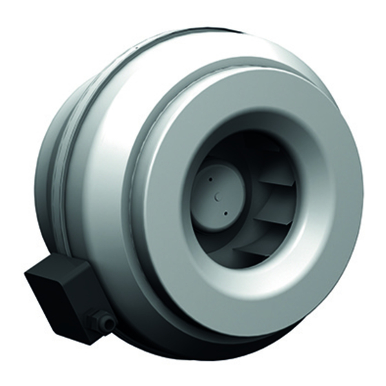
Seite 5: Beschreibung
SICHERHEITSHINWEISE Betreiben Sie den Ventilator ordnungsgemäß montiertem Ein- ausschließlich in eingebau- greifschutz oder Schutzgitter. tem Zustand oder mit Montage, elektrischer An- standsetzung nur durch ausgebil- schluss, Wartung und In- detes Fachpersonal! Betreiben Sie den Ventilator grenzen (=> Typenschild) und mit nur bestimmungsgemäß... -
Seite 6: Lagerung & Transport
LAGERUNG & TRANSPORT 5 LAGERUNG & TRANSPORT Lagern Sie den Ventilator in Nicht am Anschlusskabel seiner Originalverpackung transportieren. trocken und wettergeschützt. Das Verwinden des Gehäuses Decken Sie offene Paletten oder andere Beschädigungen mit Planen ab und schützen sind zu vermeiden. - Seite 7 MONTAGE Keine Gewalt (hebeln, bie- Anschluss nach Anschluss- gen) anwenden. bild (=> Kleber auf Ventila- torgehäuse). Befestigung an allen Befesti- gungspunkten mit geeigne- Potentialausgleichsystem ten Befestigungsmitteln (sie- ordnungsgemäß anschließen he Bild unten). Kabel ordnungsgemäß in ...
-
Seite 8: Motorschutz
7 MOTORSCHUTZ EC-Rohrventilatoren der Bauart bauseits nicht vorzusehen. Der RRV-EC haben einen integrierten Netzanschluss ist nach Kapitel 11 Motorschutz. Eine zusatzliche vorzunehmen. Überwachung des Motors ist 8 BETRIEB Vor Erstinbetriebnahme prü- fen: Einbau und elektrische Instal- Ventilator darf nicht an fest- lation fachgerecht abge- stehenden Gehäuseteilen schlossen. -
Seite 9: Betriebsbedingungen
BETRIEB Nennstromaufnahme (siehe Schutzgitter oder Ein- Typenschild) darf nicht über- greifschutz rechtzeitig auf schritten werden! Ansaugöff- Verschmutzung kontrollieren nungen immer freihalten! und wenn nötig reinigen!! 9 BETRIEBSBEDINGUNGEN Ventilatoren nicht in explosi- onsfähiger Atmosphäre be- treiben. Schalthäufigkeit: Der Ventilator ist für Dauer- betrieb S1 bemessen ... -
Seite 10: Netzanschluss
11 NETZANSCHLUSS Die Ventilatoren dürfen nur in Versorgungsspannungstol- symetrischen (zulässige Un- eranzen müssen eingehalten symetrie kleiner 2%) und im werden Kapitel 12 An- Sternpunkt geerdeten Netzen schlussbelegung. Zu hohe betrieben werden. z.B. TN-S, Spannungen können zur Zer- TN-C, TN-C-S, TN. -
Seite 11: Anschlussbelegung
Ist der Betrieb bei geprüfter An- Netzspannung und dem einlegen schlusskonfiguration nicht möglich, einer Brücke zwischen den Signa- dann nehmen Sie bitte Kontakt zur len 6 und 7 keine Reaktion der Firma COSMO GmbH auf. Drehzahl, so ist die Anschlusskon- figuration zu überprüfen. - Seite 12 ANSCHLUSSBELEGUNG 01.436 für Motor 1~230V Klemmenbelegung nach Schaltbild 01.436: X1: Netzkabel Kabel 1~230V ±10% 50 / 60 Hz ±5% Schutzleiter PE L / N / PE Ventilatorentypenschild Mains Netz X2: Steuerkabel Kabel 1~230V ±10% 50 / 60 Hz ±5% | <15V GND-PE 0-10 VDC;...
-
Seite 13: Anschlusskonfiguration
ANSCHLUSSBELEGUNG **Abbildung Sollwertvorgabe von Schaltbild Tabelle 01.436 Ventilatoren mit dem An- Falschanschluss kann zur Zer- schlussbild 01.436 haben kei- störung der Elektronik führen! ne Anschlussmöglichkeit für ein Störmelderelais. 13 ANSCHLUSSKONFIGURATION Zur Inbetriebnahme des Ventila- Anschlusskonfigurationen not- tors sind folgende alternativen wendig: 10 k Ω... -
Seite 14: Drehzahlsollwert
13.1 DREHZAHLSOLLWERT Der Drehzahlsollwert lässt sich werden von der Elektronik als durch ein angeschlossenes Po- Stoppsignal ausgewertet. Das Glei- tentiometer (S1 / 10 k Ω) von 0 bis che gilt für die Drehzahlstellung 100% stufenlos einstellen. Kleine- durch ein externes 0 – 10 Volt Sig- re Spannungssignale als 1 Volt nal. -
Seite 15: Kundendienst & Adresse
Testbetrieb: Der Motor wird von der Der Ventilator sollte im Testbe- COSMO GmbH verschlossen. trieb einwandfrei funktionieren. Veränderungen oder Reparatur sind nur durch der COSMO Spannung ausschalten GmbH und deren Vertrags- Steuerleitungen entfernen partner zulässig. Das Sollwert und Freigabe brücken (siehe Kapitel 13) Elektronikgehäuse darf zur... -
Seite 16: Nachweis Konformitätserklärung
18 NACHWEIS KONFORMITÄTSERKLÄRUNG... -
Seite 17: Eg Einbauerklärung
19 NACHWEIS EG - EINBAUERKLÄRUNG... -
Seite 18: Demontage & Entsorgung
20 NACHWEIS DEMONTAGE... -
Seite 19: Notizen
21 NOTIZEN... - Seite 20 NOTIZEN...
-
Seite 33: Declaration Of Conformity
18 DECLARATION OF CONFORMITY... -
Seite 34: Ec Declaration Of Incorporation
19 DECLARATION OF INCORPORATION... -
Seite 35: Remarks Dismounting
20 REMARKS DISMOUNTING... - Seite 36 C O S M O GMBH Brandstücken 31 22549 Hamburg i n f o @ c o s m o - i n f o . d e w w w . c o s m o - i n f o . d e BA057BB0221CG1...