Vimar SMART AUTOMATION BY-ME PLUS 01470.1 Bedienungsanleitung
Quicklinks
SMART AUTOMATION BY-ME PLUS
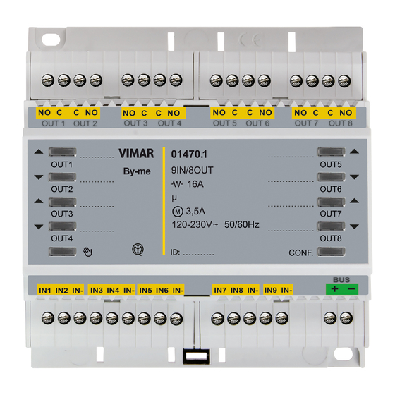
01470.1
Modulo con 9 ingressi e 8 uscite preprogrammate per applicazioni residenziali o
alberghiere, ingressi digitali programmabili per contatti privi di potenziale, uscite a
relè NO 16 A 120-230 V~ 50/60 Hz programmabili con funzione comando luci, tappa-
relle con orientamento delle lamelle, pulsanti per comando locale, domotica By-me,
installazione su guida DIN (60715 TH35), occupa 6 moduli da 17,5 mm.
CARATTERISTICHE.
• Tensione nominale di alimentazione: BUS 29 V.
• Assorbimento tipico: 10 mA.
• 8 uscite a relé (C NO) per il comando luci; i relè1+2, 3+4, 5+6 e 7+8 sono raggruppabili per
comando tapparella.
• 9 ingressi configurabili da collegare a pulsanti o interruttori tradizionali tramite conduttori di
lunghezza massima pari a 30 m (sezione minima 0,33 mm
• L'uscita 8 è utilizzabile per la gestione della pompa di circolazione.
• Pulsanti per il comando manuale dei relè.
• Pulsante per abilitare/disabilitare i comandi manuali.
• LED per lo stato delle uscite.
• LED e pulsante di configurazione.
• Grado di protezione: IP20.
• Temperatura di funzionamento: -5 °C ÷ +45°C (uso interno).
• Ingombro: 6 moduli da 17,5 mm.
• I blocchi funzionali ingressi e basculanti hanno profondità di gruppo pari a 1 (possono
cioè appartenere ad un solo gruppo).
CARICHI COMANDABILI.
• Uscita a relè (carichi comandabili a 120 - 230 V~, contatto NO):
- carichi resistivi
: 16 A (20.000 cicli);
- lampade a incandescenza
: 8 A (20.000 cicli);
- lampade fluorescenti
: 0,5 A (20.000 cicli);
- lampade a risparmio energetico
- lampade a LED
: 100 W-230 V~, 30 W-120 V~ (20.000 cicli);
- trasformatori elettronici
: 4 A (20.000 cicli);
- motori cos ø 0,6: 3,5 A (100.000 cicli).
ATTENZIONE: ciascuna delle 8 uscite a relè NO può comandare i carichi dichiarati con le
seguenti limitazioni:
- i due morsetti "C" di ciascuna delle 4 coppie di uscite sono cortocircuitati;
- la somma delle correnti circolanti sulle 8 uscite a relè non deve superare 32 A;
- la somma delle correnti circolanti su 2 uscite a relè adiacenti non deve superare 20 A.
CONFIGURAZIONE DEL DISPOSITIVO.
Per tutti i dettagli si veda il foglio istruzioni completo scaricabile dal sito www.vimar.com.
Attenzione: alla ricezione dello scenario di "DOWN tapparelle" " e "OFF luci e DOWN tap-
parelle" la discesa della tapparella inizia con un ritardo variabile da 2 s a 12 s
GESTIONE MANUALE.
La pressione del tasto
abilita l'uso dei tasti (posizionati sul frontale del dispositivo) per l'at-
tuazione dei relè; tutti i messaggi provenienti dal bus vengono ignorati. I led posti sotto ai tasti
indicano sempre lo stato del relè con la relativa numerazione.
ATTENZIONE: Nella configurazione Luci e Tapparelle, nel caso in cui sia stata collegata una
tapparella a una coppia di relè, assicurarsi che tali relè siano stati impostati per funzionare
come controllo tapparella e non per controllo luci. Comandi contemporanei dei relè potreb-
bero danneggiare il motore della tapparella.
• Sia in plug&play nella configurazione Luci e Tapparelle, sia dopo la configurazione By-me,
ogni relè che è stato impostato per il controllo luci (configurazione di default) viene comandato
attraverso il tasto con la medesima numerazione.
• Sia in plug&play nella configurazione Luci e Tapparelle, sia dopo la configurazione By-me, i
relè impostati a coppie per il controllo tapparella sono comandati dai tasti sul frontale con la
stessa numerazione per la funzione di UP (), DOWN () e STOP con tempo di inversione
nel passaggio da UP a DOWN. Ad esempio: la pressione lunga su OUT1 alza la tapparella
collegata su O1/O2, la pressione lunga su OUT2 abbassa la tapparella collegata su O1/O2, la
pressione breve su OUT1 o OUT2 ferma la tapparella oppure, se quest'ultima è ferma, ruota la
lamella (se il funzionamento scelto è tapparella + lamella).
• In plug&play nella configurazione Hotel Clima ogni relè viene comandato attraverso il tasto con la
medesima numerazione tranne le uscite 3,4,5 che sono interbloccate per non danneggiare il fancoil.
• In plug&play nella configurazione Hotel Luci ogni relè viene comandato attraverso il tasto con
la medesima numerazione.
In funzionamento non manuale la pressione dei tasti di attuazione dei relè viene ignorata.
REGOLE DI INSTALLAZIONE.
• L'installazione deve essere effettuata da personale qualificato con l'osservanza delle disposizioni
regolanti l'installazione del materiale elettrico in vigore nel paese dove i prodotti sono installati.
• Le 4 coppie di uscite a relè sono separate tra loro mediante un isolamento funzionale a 250 V~
e non da un doppio isolamento; a fronte di ciò, ad esempio, non collegare un circuito SELV ad
un'uscita che sia adiacente ad un'altra connessa alla rete di alimentazione a 230 V~.
• I circuiti di alimentazione delle uscite a relè devono essere protetti contro le sovracorrenti da
dispositivi o fusibili con potere di interruzione nominale di 1500 A oppure interruttori automatici
tipo C, con correnti nominali non superiori a 16 A.
Per le possibili installazioni si veda SI-Schemi Installativi presente su www.vimar.com ->
Prodotti -> Catalogo online in corrispondenza del codice articolo.
49401342B0 02 2201
).
2
: 100 W-230 V~, 30 W-120 V~ (20.000 cicli);
CONFORMITÀ NORMATIVA.
Direttiva BT. Direttiva EMC. Norme EN 60669-2-5, EN 50491.
Regolamento REACh (UE) n. 1907/2006 – art.33. Il prodotto potrebbe contenere tracce di piombo.
Module with 9 inputs and 8 preprogrammed outputs for residential or hotel appli-
cations, programmable digital inputs for potential-free contacts, N/O relay outputs
16 A 120-230 V~ 50/60 Hz programmable with control function for lights, roller shut-
ters with slat orientation, push-buttons for local control, By-me home automation
system, installation on DIN rails (60715 TH35), occupies 6 modules size 17.5 mm.
FEATURES.
• Rated supply voltage: BUS 29 V.
• Typical current draw: 10 mA.
• 8 relay outputs (N/O C) for lights control; relays 1+2, 3+4, 5+6 and 7+8 can be grouped for
roller shutter control.
• 9 configurable inputs for connecting to conventional switches or push-buttons via conductors
with a maximum length of 30 m (minimum section 0.33 mm
• Output 8 can be used to control the circulation pump.
• Push-buttons for manual relay control.
• Push-button to enable/disable the manual controls.
• LED for output status.
• LED and configuration button.
• Protection class: IP20.
• Operating temperature: -5 °C to +45°C (indoor use).
• Overall dimensions: 6 modules of 17.5 mm.
• The rocker buttons and input functional blocks have a group depth of 1 (that is, they can
belong to one group only).
CONTROLLABLE LOADS.
• Relay output (controllable loads at 120 - 230 V~, N/O contact):
- resistive loads
: 16 A (20,000 cycles);
- incandescent lamps
: 8 A (20,000 cycles);
- fluorescent lamps
: 0,5 A (20.000 cycles);
- energy saving lamps
: 100 W-230 V~, 30 W-120 V~ (20.000 cycles);
- LED lamps
: 100 W-230 V~, 30 W-120 V~ (20.000 cycles);
- electronic transformers
: 4 A (20,000 cycles);
- cos ø 0.6 motors: 3.5 A (100,000 cycles).
CAUTION: Each of the 8 N/O relay outputs can command the declared loads with the
following limitations:
- the two "C" terminals of each of the 4 pairs of outputs are shorted;
- the sum of the currents circulating on the 8 relay outputs must not exceed 32 A;
- the sum of the currents circulating on the 2 adjacent relay outputs must not exceed 20 A.
CONFIGURATION.
For full details see the complete instruction sheet that can be downloaded from the web-
site www.vimar.com
Caution: upon receipt of the "Roller shutters DOWN" and "Lights OFF and roller shutters DOWN"
scenario, the roller shutters begin to go down with a variable delay of between 2 s and 12 s.
MANUAL MANAGEMENT.
Pressing the
button enables the use of the buttons (located on the front of the device) to
actuate the relays. All messages from the bus are ignored. The LEDs below the buttons always
indicate the relay status with the relevant numbering.
CAUTION: If a roller shutter has been connected to a pair of relays, make sure that these relays
have been set to function for roller shutter control and not for lighting control in the Lights and
Roller shutters configuration. Simultaneous relay controls could damage the roller shutter motor.
• Both in plug&play in the Lights and Roller shutters configuration, and after By-me configuration,
each relay that has been set for lighting control (default configuration) is controlled via the
button with the same numbering.
• Both in plug&play in the Lights and Roller shutters configuration and after By-me configuration,
the relays set in pairs for roller shutter control are controlled by the buttons on the front panel
with the same numbering for the UP (), DOWN () and STOP functions with reversal time in
the passage from UP to DOWN. For example: a long press on OUT1 raises the roller shutter
connected on O1/O2, a long press on OUT2 lowers the roller shutter connected on O1/O2, a
short press on OUT1 or OUT2 stops the roller shutter or, if the latter is stationary, turns the slat
(if the chosen operation is roller shutter + slat).
• In plug&play in the Hotel Climate configuration each relay is controlled by the button with the
same numbering except outputs 3,4,5 which are interlocked to prevent damage to the fancoil.
• In plug&play in the Hotel Lights configuration, each relay is controlled by a button with the
same numbering.
In non-manual operation, pressing the relay actuation buttons is ignored.
INSTALLATION RULES.
• Installation should be carried out by qualified personnel in compliance with the current regulations
regarding the installation of electrical equipment in the country where the products are installed.
• The 4 pairs of relay outputs are separated from each other by functional insulation at 250 V~
and not by double insulation; because of this, for example, do not connect a SELV circuit
to an output that is adjacent to another one that is connected to the 230 V~ power supply.
).
2
Viale Vicenza, 14
36063 Marostica VI - Italy
www.vimar.com

Verwandte Anleitungen für Vimar SMART AUTOMATION BY-ME PLUS 01470.1


Inhaltszusammenfassung für Vimar SMART AUTOMATION BY-ME PLUS 01470.1
- Seite 1 CONFIGURAZIONE DEL DISPOSITIVO. following limitations: Per tutti i dettagli si veda il foglio istruzioni completo scaricabile dal sito www.vimar.com. - the two "C" terminals of each of the 4 pairs of outputs are shorted; Attenzione: alla ricezione dello scenario di “DOWN tapparelle” “ e “OFF luci e DOWN tap- - the sum of the currents circulating on the 8 relay outputs must not exceed 32 A;...
- Seite 2 REACH (EU) Regulation no. 1907/2006 – Art.33. The product may contain traces of lead. Pour les possibles installation, voir SI-Diagrams de connexion sur le site www.vimar.com -> Module avec 9 entrées et 8 sorties pré-programmées pour les secteurs résidentiels et Produits ->...
- Seite 3 KONFIGURATION. - λαμπτήρες εξοικονόμησης ενέργειας : 100 W-230 V~, 30 W-120 V~ (20.000 Für alle Details wird auf das zum Download auf der Website www.vimar.com verfügbare Anleitungsblatt verwiesen. κύκλοι); Warnung: beim Empfang des Szenarios “DOWN Rollläden” und “OFF Beleuchtung und - λαμπτήρες LED...
- Seite 4 .A 16 ، مع تيا ر ات مقننة ال تتجاوزC أو قواطع دوائر تلقائية من النوعA 1500 مقدرة تبلغ .بنفس الرقم >- -> المنتجاتwww.vimar.com :لالطالع على التركيبات الممكنة، انظر مخططات التركيب الموجودة على الموقع اإللكتروني .عند التشغيل غير اليدوي يتم تجاهل الضغط على أز ر ار تفعيل المرحالت...
- Seite 5 Led e Pulsante di LED and Led et bouton de Led y pulsador de LED und Λυχνία led και πλήκτρο وزر التهيئةLed مصباح διαμόρφωσης configurazione configuration button configuration configuración Konfigurationstaste Viale Vicenza, 14 36063 Marostica VI - Italy www.vimar.com 49401342B0 02 2201...
- Seite 6 أن تكون م ج ّ انية دون رشط رش اء أجهزة جديدة وذلك بالنسبة لألجهزة اإللكرتونية التي تقل أبعادها عن 52 سم. تساهم عملية الجمع املنفصل للنفايات واألجهزة القدمية هذه من أجل إعادة تدويرها ومعالجتها والتخلص منها بشكل متوافق بيئيا يف تجنب اآلثار السلبية املحتملة عىل البيئة وعىل .الصحة كام تشجع عملية إعادة تدوير املواد التي تتكون منها هذه األجهزة واملنتجات القدمية Viale Vicenza, 14 36063 Marostica VI - Italy www.vimar.com 49401342B0 02 2201...