Inhaltsverzeichnis
Werbung
Verfügbare Sprachen
Verfügbare Sprachen
Quicklinks
D G F r
6000-3940-0000-1XX 39400-0000 V100 09 ⁄ 2021
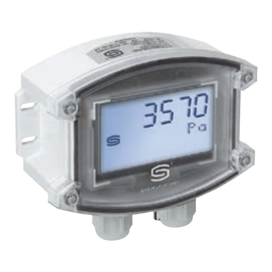
714x - Modbus
PREMASGARD
®
D
Bedienungs- und Montageanleitung
Druckfühler bzw. Messumformer für Differenzdruck
und Volumenstrom, incl. Anschluss-Set, kalibrierfähig,
mit Modbus-Anschluss
G
Operating Instructions, Mounting & Installation
Pressure sensor and measuring transducer for differential pressure
and volume flow, incl. connection set, calibratable,
with Modbus connection
F
Notice d'instruction
Sonde de pression ou convertisseur de mesure pour pression différentielle
et débit volumique, y compris kit de raccordement, étalonnable,
avec raccordement Modbus
r
Руководство по монтажу и обслуживанию
Датчик давления или измерительный преобразователь для
измерения разности давлений и объемного расхода,
вкл. комплект соединительных деталей, калибруемый,
с возможностью подключения к шине Modbus
S+S REGELTECHNIK GMBH
THURN-UND-TAXIS - STR. 22
90411 NÜRNBERG ⁄ GERMANY
FON +49 ( 0 ) 911 ⁄ 5 19 47- 0
mail@SplusS.de
www.SplusS.de
CARTONS
ET EMBALLAGE
PAPIER À TRIER
Werbung
Inhaltsverzeichnis

Verwandte Anleitungen für S+S REGELTECHNIK PREMASGARD 714 Modbus Serie


Inhaltszusammenfassung für S+S REGELTECHNIK PREMASGARD 714 Modbus Serie
- Seite 1 Датчик давления или измерительный преобразователь для измерения разности давлений и объемного расхода, вкл. комплект соединительных деталей, калибруемый, с возможностью подключения к шине Modbus S+S REGELTECHNIK GMBH THURN-UND-TAXIS - STR. 22 90411 NÜRNBERG ⁄ GERMANY CARTONS FON +49 ( 0 ) 911 ⁄ 5 19 47- 0 ET EMBALLAGE mail@SplusS.de...
- Seite 2 D G F r 714x - Modbus PREMASGARD ® Maßzeichnung PREMASGARD ® 714x - Modbus Dimensional drawing Plan coté Габаритный чертеж M16x1.5 Gehäuse mit Kabelverschraubung Gehäuse mit M12-Steckverbinder (optional) Housing with cable gland Housing with M12 connector (optional) Boîtier avec presse-étoupe Boîtier avec connecteur M12 (en option) Корпус...
-
Seite 3: Technische Daten
® PREMASGARD 714x - Modbus Rev. 0000 - V10 Wartungsfreier mikroprozessorgesteuerter PREMASGARD ® 714x - Modbus (Serie) mit Modbus-Anschluss, Gehäuse aus schlagzähem Kunststoff, wahl weise mit ⁄ ohne Display, mit Kabelverschraubung oder M12-Steckverbinder nach DIN EN 61076-2-101, zur Messung des Differenzdrucks (max. –7000...7000 Pa) in Luft. - Seite 4 ® PREMASGARD 714x - Modbus Rev. 0000 - V10 PREMASGARD ® Druckfühler bzw. Messumformer 714x - Modbus für Differenzdruck und Volumenstrom, Deluxe Messbereich Typ ⁄ WG02 Ausgang Display Art.-Nr. Druck / Volumenstrom 7148 – 500...+ 500 Pa k = 2000 PREMASGARD 7148-Modbus Modbus 130 1-7164- 0910- 20V...
- Seite 5 ® PREMASGARD 714x - Modbus Rev. 0000 - V10 ® Montageschema PREMASGARD 714x - Modbus 3570 Pa 3570 Pa 3570 Pa 3570 Pa ÜBERWACHUNGSARTEN: Die Druckanschlüsse sind am Druckschalter mit P1 (+) höherer Druck und P2 (–) niedrigerer Druck gekennzeichnet. Unterdruck P1 (+) wird nicht angeschlossen, ist luftseitig offen gegen Atmosphäre P2 (–) Anschluss im Kanal Filter...
- Seite 6 ® PREMASGARD 714x - Modbus Rev. 0000 - V10 Schaltbild ® Stecker belegung ® PREMASGARD 714x - Modbus PREMASGARD 714x - Modbus (M12) auto zero mode B mode A DIP B DIP A 1 2 3 4 5 6 1 2 3 4 5 6 7 8 Stecker MALE FEMALE...
- Seite 7 ® PREMASGARD 714x - Modbus | Konfiguration BUSADRESSE MODBUS Busadresse (binärcodiert, Wertigkeit 1 bis 247 einstellbar) DIP-Schalter [ A ] DIP 1 DIP 2 DIP 3 DIP 4 DIP 5 DIP 6 DIP 7 DIP 8 Beispiel zeigt 128 + 64 + 1 = 193 als Modbus-Adresse. Die Geräteadresse im Bereich von 1 bis 247 (Binärformat) wird über den DIP-Schalter [A] eingestellt.
-
Seite 8: Inhaltsverzeichnis
® PREMASGARD 714x - Modbus | Konfiguration ANZEIGE IM DISPL AY Standardmäßig wird in der ersten Zeile der Wert und in der zweiten Zeile die entsprechende Einheit statisch angezeigt: Differenzdruck [Pa] Über die Modbusschnittstelle kann anstelle der Standard-Anzeige eine alternative Ausgangs größe programmiert werden: Volumenstrom [m /h], Differenzdruck [Pa] Hierbei wird in der ersten Zeile der Wert und in der zweiten Zeile die entsprechende Einheit statisch angezeigt. - Seite 9 ® PREMASGARD 714x - Modbus | Konfiguration, Telegramme ASCII-Code-Tabelle für Dot Matrix Anzeigebereich ASCII Sign ASCII Sign ASCII Sign ASCII Sign ASCII Sign Leer “ & < > ü ä Ä ö Ö Ü ° Nicht in der Tabelle aufgeführte ASCII-Zeichen bzw. Steuerzeichen werden als Leerzeichen dargestellt. TELEGRAMME Function 04 Read Input Register Register...
- Seite 10 ® PREMASGARD 714x - Modbus | Telegramme Function 05 Write Single Coil Register Parameter Data Type Value Range 0x0001 Autozero (Pa) Bit 0 0 / 1 OFF - ON Function 06 Write Single Register & Function 16 Write Multiple Register Register Parameter (Display) Data Type...
- Seite 11 ® PREMASGARD 714x - Modbus | Telegramme Function 06 Write Single Register & Function 16 Write Multiple Register Register Parameter (Display) Data Type Value Range 4x0023 * k-value Unsigned 16 Bit 1...2000 1...2000 4x0024 Funktionstyp ** Unsigned 8 Bit 1...3 1...3 4x0025 * Autozero-Zeit...
-
Seite 12: Bustopologie Mit Abschluss- Und Vorspannungswiderständen
® PREMASGARD 714x - Modbus | Installation Allgemeiner Aufbau Busstruktur MODBUS RTU-Master Passiver Aktiver Abzweig Abzweig RS-485 Leitungs- Leitungs- Stammleitung abschluss abschluss (Trunk-Kabel) Stichleitung (Drop-Kabel) Slave n Stichleitung: Mehrfachabzweigung n: Slave 1 Slave 2 kürzer 20m kürzer 40m/n Bustopologie mit Abschluss- und Vorspannungswiderständen Allgemeiner Aufbau Busstruktur MODBUS RTU-Master... -
Seite 13: Wichtige Hinweise
Montage und Inbetriebnahme Hinweise zum Montage: Hinweise zur Inbetriebnahme: Der Einbau hat unter Berücksichtigung der einschlägigen, für den Dieses Gerät wurde unter genormten Bedingungen kalibriert, Mess ort gültigen Vorschriften und Standards (wie z. B. Schweiß vor- abgeglichen und geprüft. schriften usw.) zu erfolgen. Insbesondere sind zu berücksichtigen: Bei Betrieb unter abweichenden Bedingungen empfehlen wir –... -
Seite 14: Technical Data
® PREMASGARD 714x - Modbus Rev. 0000 - V10 Maintenance-free, microprocessor-controlled PREMASGARD ® 714x - Modbus (series) with Modbus connection, impact-resistant plastic housing, optionally with ⁄without display, with cable gland or M12 plug-in connector according to DIN EN 61076-2-101, for measuring the differential pressure (max. - Seite 15 ® PREMASGARD 714x - Modbus Rev. 0000 - V10 PREMASGARD ® Pressure sensor and measuring transducer 714x - Modbus for differential pressure and volume flow, Deluxe Measuring Range Type ⁄ WG02 Output Display Item no. Pressure / Volume Flow 7148 –...
- Seite 16 ® PREMASGARD 714x - Modbus Rev. 0000 - V10 ® Mounting diagram PREMASGARD 714x - Modbus 3570 Pa 3570 Pa 3570 Pa 3570 Pa TYPES OF MONITORING: Pressure connections at the pressure switch are marked with P1 (+) for higher pressure and P2 (–) for lower pressure.
- Seite 17 ® PREMASGARD 714x - Modbus Rev. 0000 - V10 Schematic diagram ® Pin assignment ® PREMASGARD 714x - Modbus PREMASGARD 714x - Modbus (M12) auto zero mode B mode A DIP B DIP A 1 2 3 4 5 6 1 2 3 4 5 6 7 8 Plug for MALE...
- Seite 18 ® PREMASGARD 714x - Modbus | Configuration BUS ADDRESS MODBUS Bus address (binary coded, value selectable from 1 to 247) DIP switch [ A ] DIP 1 DIP 2 DIP 3 DIP 4 DIP 5 DIP 6 DIP 7 DIP 8 Example shows 128 + 64 + 1 = 193 as Modbus address.
-
Seite 19: Readout In The Displ Ay
® PREMASGARD 714x - Modbus | Configuration READOUT IN THE DISPL AY By default, the first line indicates the value while the second line indicates the corresponding unit statically: Differential pressure [Pa] The Modbus interface can be used to program an alternative output variable instead of the standard display: Volume flow [m /h], differential pressure [Pa] In this case, the first line indicates the value while the second line indicates the corresponding unit statically. - Seite 20 ® PREMASGARD 714x - Modbus | Configuration, Telegrams ASCII Code Table for Dot Matrix Display Area ASCII Sign ASCII Sign ASCII Sign ASCII Sign ASCII Sign Blank “ & < > ü ä Ä ö Ö Ü ° ASCII characters or control characters are displayed as spaces. TELEGRAMS Function 04 Read Input Register Register...
- Seite 21 ® PREMASGARD 714x - Modbus | Telegrams Function 05 Write Single Coil Register Parameter Data Type Value Range 0x0001 Auto zero (Pa) Bit 0 0 / 1 OFF - ON Function 06 Write Single Register & Function 16 Write Multiple Register Register Parameter (display) Data Type...
- Seite 22 ® PREMASGARD 714x - Modbus | Telegrams Function 06 Write Single Register & Function 16 Write Multiple Register Register Parameter (display) Data Type Value Range 4x0023 * k value Unsigned 16 Bit 1...2000 1...2000 4x0024 Function type ** Unsigned 8 Bit 1...3 1...3 4x0025 *...
- Seite 23 ® PREMASGARD 714x - Modbus | Installation General layout of bus structure MODBUS RTU-Master Passive Active branch branch RS-485 Line Line Trunk line termination termination Stub line Slave n Stub line: Multiple branch n: Slave 1 Slave 2 shorter 20m shorter 40m/n Bus topology with terminating and bias resistors General layout of bus structure...
- Seite 24 Installation and Commissioning Notes on installation: Notes on commissioning: This device was calibrated, adjusted and tested under standardised Mounting shall take place while observing all relevant regulations and conditions. standards applicable for the place of measurement (e.g. such as welding When operating under deviating conditions, we recommend performing instructions, etc.).
-
Seite 25: Caractéristiques Techniques
® PREMASGARD 714x - Modbus Rev. 0000 - V10 PREMASGARD ® 714x - Modbus sans entretien, commandé par microprocesseur (série), avec raccordement Modbus, boîtier en plastique résistant aux chocs, au choix avec ⁄ sans écran, avec presse-étoupe ou connecteur M12 conforme à la norme DIN EN 61076-2-101, pour la mesure de la pression différentielle (max. - Seite 26 ® PREMASGARD 714x - Modbus Rev. 0000 - V10 ® PREMASGARD Sonde de pression ou convertisseur de mesure 714x - Modbus pour pression différentielle et débit volumique, Deluxe Plage de mesure type ⁄ WG02 sortie écran référence Pression / débit volumique 7148 –...
- Seite 27 ® PREMASGARD 714x - Modbus Rev. 0000 - V10 ® Schéma de montage PREMASGARD 714x - Modbus 3570 Pa 3570 Pa 3570 Pa 3570 Pa MODES DE SURVEILLANCE : Les prises de pression sur le pressostat sont désignées par P1 (+) pression plus élevée et par P2 (–) pression plus basse.
- Seite 28 ® PREMASGARD 714x - Modbus Rev. 0000 - V10 Schéma de raccordement ® Affectation des plots ® PREMASGARD 714x - Modbus PREMASGARD 714x - Modbus de connexion (M12) auto zero mode B mode A DIP B DIP A 1 2 3 4 5 6 1 2 3 4 5 6 7 8 Plug for MALE...
- Seite 29 ® PREMASGARD 714x - Modbus | Configuration ADRESSE DU BUS MODBUS Adresse du bus (code binaire, valance réglable de 1 à 247) Interrupteur DIP [ A ] DIP 1 DIP 2 DIP 3 DIP 4 DIP 5 DIP 6 DIP 7 DIP 8 suit l'adresse Modbus 128 + 64 + 1 = 193 L'adresse de l'appareil dans une plage de 1 à...
- Seite 30 ® PREMASGARD 714x - Modbus | Configuration AFFICHAGE SUR L'ÉCRAN Par défaut, la valeur est affichée sur la première ligne et l’unité correspondante est affichée de manière statique sur la seconde ligne : Pression différentielle [Pa] Via l’interface Modbus, une grandeur de sortie alternative peut être programmée au lieu de l’affichage standard : débit volumique [m /h], pression différentielle [Pa] La valeur s'affiche dans la première ligne et l'unité...
- Seite 31 ® PREMASGARD 714x - Modbus | Configuration, Télégrammes Tableau des codes ASCII pour la zone d'affichage de la matrice de points ASCII Sign ASCII Sign ASCII Sign ASCII Sign ASCII Sign Espace “ & < > ü ä Ä ö Ö...
- Seite 32 ® PREMASGARD 714x - Modbus | Télégrammes Function 05 Write Single Coil Data Type Value Range Registre Paramètres 0x0001 Autozero (Pa) Bit 0 0 / 1 OFF - ON Function 06 Write Single Register & Function 16 Write Multiple Register Registre Paramètres (écran) Data Type...
- Seite 33 ® PREMASGARD 714x - Modbus | Télégrammes Function 06 Write Single Register & Function 16 Write Multiple Register Registre Paramètres (écran) Data Type Value Range 4x0023 * Valeurs k Unsigned 16 Bit 1...2000 1...2000 4x0024 Type de fonction ** Unsigned 8 Bit 1...3 1...3 4x0025 *...
- Seite 34 ® PREMASGARD 714x - Modbus | Installation Structure générale du bus MODBUS RTU-Master Raccord Raccord actif passif RS-485 Fin de ligne Fin de ligne Ligne principale (câble principal) Tronçon (câble de dérivation) Slave n Tronçon : Poly-raccord n : Slave 1 Slave 2 moins de 20 m moins de 40 m / n...
-
Seite 35: Montage Et Mise En Service
Montage et mise en service Consignes demontage : Consignes de mise en service : L'installation doit être effectuée en conformité avec les réglementations Cet appareil a été étalonné, ajusté et testé dans des conditions et les normes en vigueur pour le lieu de mesure (par ex. règles de normalisées. -
Seite 36: Технические Данные
® PREMASGARD 714x - Modbus Rev. 0000 - V10 Не нуждающийся в техническом обслуживании, управляемый микропроцессором датчик PREMASGARD ® 714x - Modbus (серия) с возможностью подключения к шине Modbus, корпус из ударопрочного пластика, на выбор с дисплеем или без дисплея, с резьбовым кабельным вводом либо разъемом ... - Seite 37 ® PREMASGARD 714x - Modbus Rev. 0000 - V10 ® PREMASGARD Датчик давления или измерительный преобразователь 714x - Modbus для измерения разности давлений и объемного расхода, Deluxe Диапазон измерения Тип ⁄ WG02 Выход Дисплей Арт. № Давление/объемный расход 7148 – 500...+ 500 Pa k = 2000 PREMASGARD 7148-Modbus Modbus...
- Seite 38 ® PREMASGARD 714x - Modbus Rev. 0000 - V10 ® Схема монтажа PREMASGARD 714x - Modbus 3570 Pa 3570 Pa 3570 Pa 3570 Pa ВИДЫ КОНТРОЛЯ ДАВЛЕНИЯ: Присоединительные патрубки для давления обозначены на реле давления как P1 (+) более высокое давление и P2 (–) более...
- Seite 39 ® PREMASGARD 714x - Modbus Rev. 0000 - V10 Схема подключения ® Разводка контактов ® PREMASGARD 714x - Modbus PREMASGARD 714x - Modbus (M12) auto zero mode B mode A DIP B DIP A 1 2 3 4 5 6 1 2 3 4 5 6 7 8 Plug for MALE...
- Seite 40 ® PREMASGARD 714x - Modbus | Конфигурация А ДРЕС ШИНЫ MODBUS Адрес шины (двоичный, настраиваемая значимость от 1 до 247) DIP-переключатель [ A ] DIP 1 DIP 2 DIP 3 DIP 4 DIP 5 DIP 6 DIP 7 DIP 8 Данный...
-
Seite 41: Индик Ация На Дисплее
® PREMASGARD 714x - Modbus | Конфигурация ИНДИК АЦИЯ НА ДИСПЛЕЕ Стандартно в первой строке статично отображается значение, а во второй — соответствующая единица измерения: разность давлений [Па] Используя шинный интерфейс, вместо стандартной индикации можно запрограммировать отображение альтернативной выходной величины: объемный расход [м /ч], разность... - Seite 42 ® PREMASGARD 714x - Modbus | Конфигурация, Телеграммы Таблица кодов ASCII для полей с точечной матрицей ASCII Символ ASCII Символ ASCII Символ ASCII Символ ASCII Символ Пробел “ & < > ü ä Ä ö Ö Ü ° Неуказанные в таблице символы ASCII или управляющие символы отображаются в виде пробела. ТЕЛЕГРАММЫ...
- Seite 43 ® PREMASGARD 714x - Modbus | Телеграммы Функция 05 — Запись значения одного флага (Write Single Coil) Регистр Параметр Тип данных Значение Диапазон 0x0001 Автоматическая установка нуля (Па) Bit 0 0 / 1 OFF - ON Функция 06 — Запись значения в один регистр хранения (Write Single Register) и функция...
- Seite 44 ® PREMASGARD 714x - Modbus | Телеграммы Функция 06 — Запись значения в один регистр хранения (Write Single Register) и функция 16 — Запись значений в несколько регистров хранения (Write Multiple Register) Регистр Параметры (дисплей) Тип данных Значение Диапазон 4x0023 * Коэффициент...
- Seite 45 ® PREMASGARD 714x - Modbus | Подключение Общая структура шины MODBUS RTU-Master Пассивное Активное ответвление ответвление RS-485 Оконечная Оконечная Магистральная нагрузка нагрузка линия шины шины (магистральный кабель) Тупиковая линия (ответвитель- Slave n ный кабель) Тупиковая Многократное линия: ответвление n: Slave 1 Slave 2 короче...
-
Seite 46: Важные Указания
Монтаж и ввод в эксплуатацию Указания по монтажу: Указания по вводу в эксплуатацию: Монтаж должен осуществляться с учетом соответствующих, действи- Этот прибор был откалиброван, отъюстирован и проверен в тельных для места измерения предписаний и стандартов (например, стандартных условиях. инструкции для сварочных работ). В особенности следует принимать Во... - Seite 47 Reprint in full or in parts requires permission from S+S Regeltechnik GmbH. La reproduction des textes même partielle est uniquement autorisée après accord de la société S+S Regeltechnik GmbH. Перепечатка, в том числе в сокращенном виде, разрешается лишь с согласия S+S Regeltechnik GmbH.
- Seite 48 D G F r Busadresse, binärcodiert Bus address, binary coded Adresse du bus, code binaire Адресс шины, двоичный 0 0 0 0 0 0 0 1 0 0 1 1 0 0 1 1 0 1 1 0 0 1 0 1 1 0 0 1 0 1 1 1 1 1 0 0 1 0 0 1 0 0 0 0 0 0 1 0...