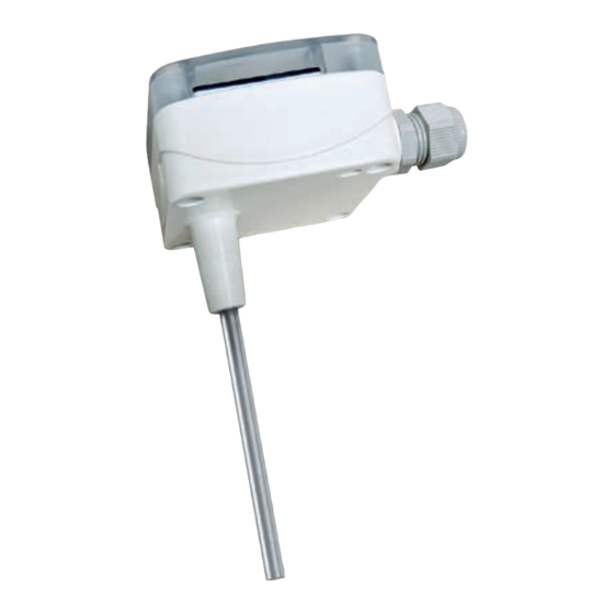
S+S REGELTECHNIK THERMASGARD TM65 Bedienungs- Und Montageanleitung
Temperaturmessumformer, kalibrierfähig, mit mehrbereichsumschaltung und aktivem ausgang
Vorschau ausblenden
Andere Handbücher für THERMASGARD TM65:
- Montageanleitung (17 Seiten) ,
- Bedienungs- und montageanleitung (17 Seiten) ,
- Bedienungs- und montageanleitung (32 Seiten)
Inhaltsverzeichnis
Werbung
Verfügbare Sprachen
Verfügbare Sprachen
D G F r
6003-0700-2012-000 30700-2015 04 ⁄ 2015
THERMASGARD
®
D
Bedienungs- und Montageanleitung
Temperaturmessumformer,
kalibrierfähig, mit Mehrbereichsumschaltung
und aktivem Ausgang
G
Operating Instructions, Mounting & Installation
Temperature measuring transducers,
calibrateable, with multi-range switching
and active output
F
Notice d'instruction
Sondes avec convertisseur de mesure,
étalonnable, avec commutation multi-gamme
et sortie active
r
Руководство по монтажу и обслуживанию
Преобразователь температуры измерительный,
калибруемый, с переключением между несколькими
диапазонами и активным выходом
S+S REGELTECHNIK GMBH
PIRNAER STRASSE 20
90411 NÜRNBERG ⁄ GERMANY
FON +49 (0) 911 ⁄ 5 19 47- 0
FAX +49 (0) 911 ⁄ 5 19 47- 70
mail@SplusS.de
www.SplusS.de
TM 65
Herzlichen Glückwunsch!
Sie haben ein deutsches Qualitätsprodukt erworben.
Congratulations!
You have bought a German quality product.
Félicitations !
Vous avez fait l'acquisition d'un produit allemand de qualité.
Примите наши поздравления !
Вы приобрели качественный продукт, изготовленный в Германии.
TM 65
TM 65
mit Display
with display
avec écran
с дисплеем
Werbung
Inhaltsverzeichnis

Verwandte Anleitungen für S+S REGELTECHNIK THERMASGARD TM65


Inhaltszusammenfassung für S+S REGELTECHNIK THERMASGARD TM65
- Seite 1 диапазонами и активным выходом TM 65 mit Display with display avec écran с дисплеем S+S REGELTECHNIK GMBH Herzlichen Glückwunsch! Sie haben ein deutsches Qualitätsprodukt erworben. PIRNAER STRASSE 20 Congratulations! 90411 NÜRNBERG ⁄ GERMANY You have bought a German quality product.
- Seite 2 D G F r TM 65 THERMASGARD ® TM 65 MF - 15 - K Maßzeichnung Maßzeichnung Dimensional drawing Dimensional drawing Plan coté Plan coté Габаритный чертеж Габаритный чертеж M16x1,5 ø 6 MF - 15 - K TM 65 TM 65 Montageflansch aus Kunststoff ohne Display mit Display...
-
Seite 3: Technische Daten
THERMASGARD ® TM 65 Rev. 2015 - 1.0 DE Kalibrierfähiger Temperaturmessumformer THERMASGARD ® TM 65 mit acht umschalt- Schaltbild TM 65 - I baren Messbereichen, stetigem linearem Ausgang, mit Gehäuse aus schlagzähem Kunststoff, Gehäusedeckel mit Schnellverschluss schrauben, geradem Schutzrohr und wahlweise 230V AC mit und ohne Display. -
Seite 4: Temperaturbereiche
Messumformer, kalibrierfähig, mit aktivem Ausgang Bürdendiagramm Ausgang: ........ 4...20 mA Bürdendiagramm Anschluss: ......2-Leiteranschluss 4 … 20 mA Hilfsenergie: ......15...36 V DC ± 10 %, Speisung aus 4...20 mA Schleife, Restwelligkeit stabilisiert ≤ ± 0,3 V Bürde: ........Ra (Ohm) = (Ub -14 V) ⁄ 0,02 A Ausgang: ........ -
Seite 5: Montage Und Installation
Montage und Installation Die Geräte sind im spannungslosen Zustand anzuschließen. Der Der Einbau hat unter Beachtung der Übereinstimmung der vorlie- genden technischen Parameter der Thermometer mit den realen Anschluss der Geräte darf nur an Sicherheitskleinspannung er- Einsatzbedingungen zu erfolgen, insbesondere: folgen. -
Seite 6: Technical Data
THERMASGARD ® TM 65 Rev. 2015 - 1.0 GB Calibratable temperature measuring transducer THERMASGARD ® TM 65 with eight switch- Connecting scheme TM 65 - I able measuring ranges, continuous linear output, enclosure made of impact-resistant plastic and enclosure cover with quick-locking screws, straight protective tube, with or without op- 230V AC tional display. - Seite 7 Measuring transducers, calibrateable, with active output Load resistance diagram Output: ......4...20 mA Load resistance diagram Connection: ......2-wire connection 4 … 20 mA Auxiliary energy: ....15 ... 36 V DC ± 10 %, supplied from 4...20 mA loop, residual ripple, stabilised ≤ ± 0.3 V Working resistance:..Ra (Ohm) = (Ub-14 V) ⁄...
- Seite 8 Mounting and Installation Devices are to be connected under dead-voltage condition. Devices Before mounting, make sure that the existing thermometer‘s techni- cal parameters comply with the actual conditions at the place of must only be connected to safety extra-low voltage. Consequential utilization, in particular in respect of: damages caused by a fault in this device are excluded from war- ranty or liability.
-
Seite 9: Caractéristiques Techniques
THERMASGARD ® TM 65 Rév. 2015 - 1.0 FR Sonde de température avec convertisseur, étalonnable, THERMASGARD ® TM 65, avec Schéma de raccordement TM 65 - I huit plages de mesure commutables, sortie linéaire analogique, boîtier en matière plastique résiliente, couvercle de boîtier avec vis de fermeture rapide, tube de protection droit, 230V AC au choix avec ou sans écran. - Seite 10 Convertisseur de mesure étalonnable avec sortie active Load resistance diagram Sortie: ......4 ... 20 mA Diagramme de charge Raccordement: ....2 fils 4 … 20 mA Auxiliary energy: ....15 ... 36 V cc ± 10 %, alimentation par boucle 4...20 mA, Ondulation résiduelle stabilisée ≤...
-
Seite 11: Montage Et Installation
Montage et installation Les raccordements électriques doivent être exécutés HORS Effectuer l’installation en respectant la conformité des paramètres techniques correspondants des thermomètres aux TENSION. Veillez à ne brancher l’appareil que sur un réseau de très basse tension de sécurité. Nous déclinons toute responsabi- conditions d’utilisation réelles, notamment : lité... -
Seite 12: Технические Данные
THERMASGARD ® TM 65 Rev. 2015 - 1.0 RU Калибруемый измерительный преобразователь температуры THERMASGARD ® TM 65 с Схема соединения TM 65 - I переключением между восьмью диапазонами измерения, постоянным линейным выходом, корпус из ударопрочного пластика, крышка корпуса с быстрозаворачиваемыми винтами, 230V AC прямой... -
Seite 13: Напряжение Питания
Преобразователи измерительные, калибруемые, с активным выходом Load resistance diagram Выходом: ......... 4...20 мA Нагрузочная диаграмма Подключение: ......по двухпроводной схеме 4 … 20 мA Вспомогательное напряжение: ... 15 ... 36 B постоянного тока ± 10 %, питание из петли 4...20 мА, остат. -
Seite 14: Монтаж И Подключение
Монтаж и подключение Приборы следует устанавливать в обесточенном состоянии. Под- Монтаж следует осуществлять с учетом соответствия прилагаемых тех- ключение должно осуществляться исключительно к безопасно нических параметров термометра реальным условиям эксплуатации, малому напряжению. Повреждения приборов вследствие несо- в особенности: блюдения упомянутых требований не подлежат устранению по –... - Seite 15 Reprints, in part or in total, are only permitted with the approval of S+S Regeltechnik GmbH. La reproduction des textes même partielle est uniquement autorisée après accord de la société S+S Regeltechnik GmbH. Перепечатка, в том числе в сокращенном виде, разрешается лишь с согласия S+S Regeltechnik GmbH.
- Seite 16 D G F r TM 65 THERMASGARD ® TM 65 - U Anschlussbild * TM 65 - I Anschlussbild DIP-Schalter DIP-Schalter Kontakt- Kontakt- Messbereichs- Messbereichs- seite seite umschaltung umschaltung 1 2 3 1 2 3 interner Sensor interner Sensor min. max.