Inhaltsverzeichnis

Verwandte Anleitungen für HYDAC ELECTRONIC HLT 2500-F1


Inhaltszusammenfassung für HYDAC ELECTRONIC HLT 2500-F1
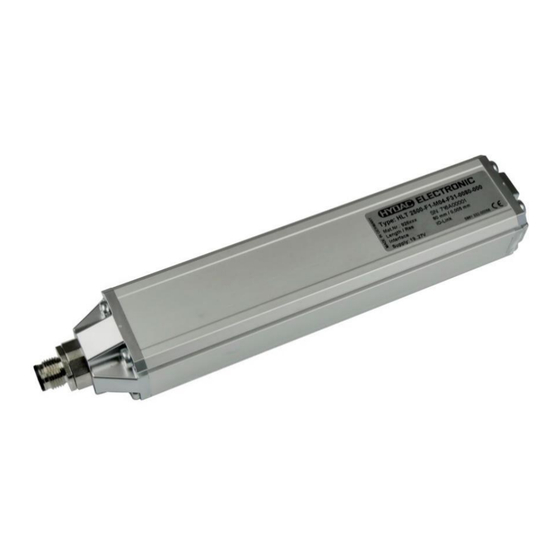
- Seite 1 Linear Wegmessumformer Linear Position Transmitter HLT 2500-F1 Mit IO-Link Schnittstelle With IO-Link Interface Bedienungsanleitung (Originalanleitung) Operating Instructions (Translation of original instructions)
-
Seite 2: Inhaltsverzeichnis
HLT 2500-F1 IO-Link Inhalt Allgemeine Hinweise 1.1 Haftungsausschluss 1.2 Gewährleistung 1.3 Geltungsbereich 1.4 Hersteller-Erklärung 1.5 Verwendete Abkürzungen und Begriffe Sicherheit 2.1 Symbole und Hinweise 2.2 Bestimmungsgemäßer Gebrauch / vorhersehbarer Fehlgebrauch 2.3 Verpflichtung des Betreibers vor der Inbetriebnahme 2.4 Personalauswahl und Qualifikation; Grundsätzliche Pflichten 2.5 Organisatorische Maßnahmen... - Seite 3 HLT 2500-F1 IO-Link System-Kommandos Fehlermeldungen, Warnungen, Events 11.1 ISDU-Fehlertypen 11.2 Sonstige Störungen Anschlussbelegung Technische Daten Bestellangaben Lieferumfang Geräteabmessungen Zubehör 17.1 Elektrischer Anschluss 17.2 Magnete und Einbauzubehör Kontakt Anhang / Annex: IODD Einstellparameter / IODD Setting Parameters Stand: 08.03.2022 HYDAC ELECTRONIC GMBH...
- Seite 4 HLT 2500-F1 IO-Link Vorwort Für Sie, den Benutzer unseres Produktes, haben wir in dieser Dokumentation die wichtigsten Hinweise zum Bedienen und Warten zusammengestellt. Sie dient Ihnen dazu, das Produkt kennen zu lernen und seine bestimmungs- gemäßen Einsatzmöglichkeiten optimal zu nutzen.
-
Seite 5: Allgemeine Hinweise
HLT 2500-F1 IO-Link 1 Allgemeine Hinweise Überprüfen Sie vor der Inbetriebnahme den Zustand des Gerätes sowie des mitgelieferten Zubehörs. Lesen Sie vor der Inbetriebnahme des Gerätes die Bedienungsanleitung und stellen Sie sicher, dass das Gerät für Ihre Anwendung geeignet ist. -
Seite 6: Hersteller-Erklärung
Normen und Richtlinien entwickelt, konstruiert und gefertigt. Eine entsprechende Hersteller-Erklärung kann bei der Firma HYDAC ELECTRONIC GMBH angefordert werden. Der Hersteller der Produkte, die HYDAC ELECTRONIC GMBH, besitzt ein zertifiziertes Qualitätssicherungssystem gemäß ISO 9001. 1.5 Verwendete Abkürzungen und Begriffe... -
Seite 7: Bestimmungsgemäßer Gebrauch / Vorhersehbarer Fehlgebrauch
HLT 2500-F1 IO-Link 2.2 Bestimmungsgemäßer Gebrauch / vorhersehbarer Fehlgebrauch Mängel- und Haftungsansprüche – gleich aus welchem Rechtsgrund – bestehen ins- besondere nicht bei fehlerhafter oder unsachgemäßer Installation, Inbetriebnahme, Verwendung, Behandlung, Lagerung, Wartung, Reparatur, Einsatz ungeeigneter Betriebsmittel oder sonstiger nicht vom Hersteller zu verantwortenden Umständen. -
Seite 8: Allgemeine Gefahren Bei Der Verwendung Des Produkts
HLT 2500-F1 IO-Link 2.6 Allgemeine Gefahren bei der Verwendung des Produkts Das Produkt, nachfolgend als Mess-System bezeichnet, ist nach dem Stand der Technik und den anerkannten sicherheitstechnischen Regeln gefertigt. Dennoch können bei nicht bestimmungsgemäßer Verwendung Gefahren für Leib und Leben des Benutzers oder Dritter bzw. -
Seite 9: Transport, Verpackung, Lagerung
HLT 2500-F1 IO-Link Das Mess-System enthält elektrostatisch gefährdete Bauelemente und Baugruppen, die durch unsachgemäße Behandlung zerstört werden können. Berührungen der Mess-System-Anschlusskontakte mit den Fingern sind zu vermeiden, bzw. sind die entsprechenden ESD- Schutzmaßnahmen anzuwenden. Geräteausführungen Kundenspezifische Geräteausführungen, einschließlich der Anschlusstechnik, können sich von den hier und in den schnittstellen-... -
Seite 10: Allgemeine Funktionsbeschreibung
HLT 2500-F1 IO-Link 6 Allgemeine Funktionsbeschreibung Das Messprinzip basiert auf einer Laufzeitmessung (Ultraschallbereich). Die Ultraschall-Laufzeit ist wegproportional und wird in einer Elektronik ausgewertet. In einem Schutzrohr ist ein ferromagnetischer Draht (magnetostriktives Messelement – Wellenleiter) gespannt, der mit einem Stromimpulse beaufschlagt wird. Durch den Stromimpuls entsteht um den Draht ein radiales Magnetfeld. -
Seite 11: Montage
HLT 2500-F1 IO-Link 7 Montage 7.1 Allgemeine Montagehinweise Bei der Montage des HYDAC Linear-Wegsensors ist darauf zu achten, dass keine starken magnetischen und elektrischen Störfelder im Bereich des Sensors auftreten. Unzulässige Störfelder können die Messgenauigkeit beeinflussen. Im Bereich des Mess-Stabes darf die Feldstärke max. 3 mT betragen. -
Seite 12: Zusätzliche Montagehinweise
HLT 2500-F1 IO-Link 7.2 Zusätzliche Montagehinweise Zusätzliche Montagehinweise, die erfahrungsgemäß den Einfluss elektromagnetischer Störungen reduzieren: Möglichst kurze Leitungsverbindungen herstellen. Möglichst ungeschirmte Leitungen verwenden Direkte Nähe zu Verbindungsleitungen von Leistungsverbrauchern oder störenden Elektro- oder Elektronikgeräten ist möglichst zu vermeiden. -
Seite 13: Einstellbare Geräteparameter
HLT 2500-F1 IO-Link 8.3.1 Einstellbare Geräteparameter Zählrichtung (definiert, ob steigende oder fallende Positionswerte vom Mess- System ausgegeben werden, wenn der Magnet zum Stabende geführt wird) Auflösung (definiert die Länge eines Messschrittes. Über die hier eingestellte Auflösung und die im Mess-System hinterlegten Messlänge ergibt sich die Gesamtschrittzahl über den gesamten Messbereich des Mess-Systems... -
Seite 14: Parametrierung
HLT 2500-F1 IO-Link 9 Parametrierung 9.1 Parametrierung im SDCI-Mode (IO-Link Modus) Das Mess-System kann über die IO-Link-Schnittstelle mit jedem IO-Link-fähigen Master- Konfigurationstool (gemäß IO-Spezifikation V1.1) parametriert werden. Die IO-Link- Spezifikation V1.0 wird ebenfalls unterstützt. Wird der eingelesene Parametersatz vom Gerät nicht akzeptiert, empfehlen wir den Parametersatz auf Plausibilität zu überprüfen. -
Seite 15: System-Kommandos
HLT 2500-F1 IO-Link 10 System-Kommandos Das Mess-System unterstützt die System-Kommandos Set Position und Restore Factory Settings (Auslieferungszustand wiederherstellen). Die Set Position-Funktion wird verwendet, um die aktuell ausgegebene Position auf einen beliebigen Positionswert zu setzen. Gefahr Personenschaden Sachschaden durch einen Istwertsprung bei Ausführung der Set position Funktion! Die Set position Funktion sollte nur im Mess-System-Stillstand ausgeführt werden. - Seite 16 HLT 2500-F1 IO-Link - Verfügbare Indizes, siehe 0x80 0x11 Index nicht verfügbar Kap.9 Parametrierung Subindex nicht Verfügbare Subindizes, siehe 0x80 0x12 verfügbar Kap.9 Parametrierung - Geräte-Betriebszustand überprüfen Service zurzeit nicht 0x80 0x20 - Service wiederholen verfügbar - Gerät AUS/EIN - Externe Zugriffe sperren Service zurzeit nicht (Gerätesteuerungskonsole)
-
Seite 17: Sonstige Störungen
HLT 2500-F1 IO-Link 11.2 Sonstige Störungen Störung Ursache Abhilfe Vibrationen, Schläge und Stöße z.B. Pressen, werden genannten "Schockmodulen" Starke Vibrationen gedämpft. Wenn der Fehler trotz dieser Maßnahmen wiederholt auftritt, muss das Mess-System Positionssprünge des getauscht werden. Mess-Systems Gegen elektrische Störungen helfen... -
Seite 18: Technische Daten
HLT 2500-F1 IO-Link 13 Technische Daten Eingangskenngrößen Messbereiche 50 .. 4000 mm Bauform Flachprofil, ohne Magnetführung Material Messkörper: Aluminium Ausgangsgrößen Auflösung 0,005; 0,01; 0,02; 0,1 ≤ ± 0,1 mm (Messbereich ≤ 1.500 mm) Nicht-Linearität ≤ ± 0,15 mm (Messbereich > 1.500 mm) (Messbereich ≤... -
Seite 19: Bestellangaben
HLT 2500-F1 IO-Link 14 Bestellangaben HLT 2 5 0 0 – F1 – 006 – F31 – XXXX – 000 Bauart/Geometrietyp = Profil Bauform = Flachprofil, ohne Magnetführung Anschlussart, elektrisch 006 = Gerätestecker M12x1, 4-pol. Ausgangssignal F31 = IO-Link Schnittstelle... -
Seite 20: Geräteabmessungen
HLT 2500-F1 IO-Link 16 Geräteabmessungen Stand: 08.03.2022 HYDAC ELECTRONIC GMBH Mat. Nr.: 670083... -
Seite 21: Zubehör
HLT 2500-F1 IO-Link 17 Zubehör 17.1 Elektrischer Anschluss ZBE 06 (4-pol.) Kupplungsdose M12x1, abgewinkelt Kabeldurchmesser: 3,3 .. 6,6 mm Material-Nr.: 6006788 ZBE 06-02 (4-pol.) Kupplungsdose M12x1, abgewinkelt mit 2 m Leitung, Material-Nr.: 6006790 ZBE 06-05 (4-pol.), Kupplungsdose M12x1, abgewinkelt mit 5 m Leitung Farbkennung: Material-Nr.: 6006789... - Seite 22 HLT 2500-F1 IO-Link ZBL MF55-20 Positionsmagnet für HLT 2500-F1 Material-Nr.: 6084457 Stand: 08.03.2022 HYDAC ELECTRONIC GMBH Mat. Nr.: 670083...
-
Seite 23: Kontakt
HLT 2500-F1 IO-Link Kontakt HYDAC ELECTRONIC GMBH Hauptstr. 27 D-66128 Saarbrücken Germany Web: www.hydac.com E-Mail: electronic@hydac.com Tel.: +49 (0)6897 509-01 Fax.: +49 (0)6897 509-1726 HYDAC Service Für Fragen zu Reparaturen steht Ihnen der HYDAC Service zur Verfügung. SYSTEMS & SERVICES GMBH HYDAC Hauptstr. - Seite 24 Notizen / Notes / Notes ...
- Seite 25 Linear Position Transmitter HLT 2500-F1 with IO-Link Interface Operating instructions (Translation of original instructions)
- Seite 26 HLT 2500-F1 IO-Link Content General information 1.1 Exclusion of liability 1.2 Warranty 1.3 Scope of application 1.4 Declaration of manufacturer 1.5 Abbreviations and definitions Security 2.1 Symbols and Notes 2.2 Intended use / foreseeable misuse 2.3 Responsibility of the operator before start-up 2.4 Personnel selection and qualification;...
- Seite 27 HLT 2500-F1 IO-Link System commands Error messages, warnings, events 11.1 ISDU Error types 11.2 Other errors Pin assignment Tecnical data Order details Scope of delivery Device dimensions Accessories 17.1 Electrical connection 17.2 Magnets and installation accessories Contact Anhang / Annex: IODD Einstellparameter / IODD Setting...
- Seite 28 HLT 2500-F1 IO-Link Preface The instructions provide you, as user of our product, with key information on the operation and maintenance of the equipment. It will acquaint you with the product and assist you in obtaining maximum benefit in the applications for which it is designed.
-
Seite 29: General Information
HLT 2500-F1 IO-Link 1 General information Before commissioning, check the device and all accessories supplied. Before commissioning the device, please read the operating instructions. Ensure that the device is suitable for your application. If the instrument is not handled correctly, or if the operating instructions and specifications are not adhered to, damage to property and/or personal injury can result. -
Seite 30: Declaration Of Manufacturer
European standards and directives. A corresponding manufacturer’s declaration can be requested from HYDAC ELECTRONIC GMBH. The manufacturer of the product, HYDAC ELECTRONIC GMBH, operates a certified quality assurance system in accordance with ISO 9001. 1.5 Abbreviations and definitions... -
Seite 31: Intended Use / Foreseeable Misuse
HLT 2500-F1 IO-Link 2.2 Intended use / foreseeable misuse Claims for defects or liability, regardless of the legal foundation, specifically do not apply with incorrect or improper installation, commissioning, usage, handling, storage, maintenance, repair, use of unsuitable components or other circumstances for which the manufacturer is not responsible. -
Seite 32: General Risks When Using The Product
HLT 2500-F1 IO-Link 2.6 General risks when using the product The product, hereinafter referred to as "the measurement system", is manufactured according to state-of-the-art technology and accepted safety rules. Nevertheless, improper use can pose a danger to life and limb of the user or third parties, or lead... -
Seite 33: Transportation, Packaging, Storage
HLT 2500-F1 IO-Link The measurement system contains electrostatically endangered circuit elements and units which can be destroyed by improper use. Touching the measurement system connection contacts with bare fingers must be avoided, resp. the appropriate ESD protective measures are applicable. -
Seite 34: General Functional Description
HLT 2500-F1 IO-Link 6 General functional description The measuring method is based on a runtime measurement (in the ultrasonic range). The ultrasound propagation runtime is proportional to the distance and is processed in an evaluation unit. A ferro-magnetic conductor is tensioned and supplied with a current pulse (magnetostrictive measuring element –... -
Seite 35: Assembly
HLT 2500-F1 IO-Link 7 Assembly 7.1 General installation notes Before mounting HYDAC Linear Position Transmitter, make sure there are no strong magnetic and electric interference fields nearby. Inadmissible interference fields can influence the measuring accuracy. The field strength may be max. 3 mT in direct proximity of the measuring rod. -
Seite 36: Additional Installation Instructions
HLT 2500-F1 IO-Link 7.2 Additional installation instructions Additional installation instructions which, from experience, reduce the effect of electromagnetic interference: Make line connections as short as possible. Use unshielded cabling. Keep the instrument well away from the electrical supply lines of power equipment, as well as from any electrical or electronic equipment causing interference. -
Seite 37: Adjustable Device Parameters
HLT 2500-F1 IO-Link 8.3.1 Adjustable device parameters Code sequence (defines whether increasing or decreasing position values are shown when the magnet is guided to the rod end). Resolution (defines the length of a measurement step). The total number of... -
Seite 38: Parameterisation
HLT 2500-F1 IO-Link 9 Parameterisation 9.1 Parameterisation in SDCI mode (IO-Link mode) The measurement system can be parametrised via the IO-Link interface by means of any IO-Link compatible master configuration tool (according IO specifications V1.1). IO-Link specifications V1.0 are as well supported. -
Seite 39: System Commands
HLT 2500-F1 IO-Link 10 System commands The measurement system supports the system commands Set Position and Restore Factory Settings (restore factory default settings). The Set-position function is used in order to set the currently output position to a freely defined position value. - Seite 40 HLT 2500-F1 IO-Link Sub index not Available sub indices, see chap.9 0x80 0x12 available Parameterisation - check device operation mode Service currently not 0x80 0x20 - repeat service available - Device OFF/ON - Refuse external access Service currently not (device control panel)
-
Seite 41: Other Errors
HLT 2500-F1 IO-Link 11.2 Other errors Error Cause Remedy Vibrations, impacts and shocks, e.g. on presses, are dampened by "shock Strong vibrations modules". If the error recurs despite these measures, the measuring Position skips of the system must be replaced. -
Seite 42: Tecnical Data
HLT 2500-F1 IO-Link 13 Tecnical data Input data Measuring Ranges 50 .. 4000 mm Type of construction Flat profile, without magnet guidance Material Measuring body: aluminium Output data Resolution: 0.005; 0.01; 0.02; 0.1 ≤ ± 0.1 mm (measuring range ≤ 1500 mm) Non-linearity ≤... -
Seite 43: Order Details
HLT 2500-F1 IO-Link 14 Order details HLT 2 5 0 0 – F1 – 006 – F31 – XXXX – 000 Design/Geometry type = Profile Type of construction = Flat profile, without magnetic guidance Electrical connection 006 = plug connector, M 12x1, 4 pole... -
Seite 44: Device Dimensions
HLT 2500-F1 IO-Link 16 Device dimensions Rod length = Measuring length + 140 Damping zone 65 Measuring length Damping zone 75 movable Plug connector Edition: 2022-03-08 HYDAC ELECTRONIC GMBH Part no.: 670083... -
Seite 45: Accessories
HLT 2500-F1 IO-Link 17 Accessories 17.1 Electrical connection ZBE 06 (4 poles) Mating connector M12x1, right angle Cable diameter: 3.3 .. 6.6 mm Part No.: 6006788 ZBE 06-02 (4 pole) Mating connector M12x1, right-angle with 2 m cable, Part No.:... - Seite 46 HLT 2500-F1 IO-Link ZBL MF55-20 Position magnet for HLT 2500-F1 Part no.: 6084457 Edition: 2022-03-08 HYDAC ELECTRONIC GMBH Part no.: 670083...
-
Seite 47: Contact
HLT 2500-F1 IO-Link Contact HYDAC ELECTRONIC GMBH Hauptstrasse 27 D-66128 Saarbruecken Germany Web: www.hydac.com Email: electronic@hydac.com Phone: +49 (0)6897 509-01 Fax: +49-(0)6897-509-1726 HYDAC Service For enquiries about repairs or alterations, please contact HYDAC Service. HYDAC SYSTEMS & SERVICES GMBH Hauptstrasse 27... -
Seite 48: Anhang / Annex: Iodd Einstellparameter / Iodd Setting Parameters
HLT 2500-F1 IO-Link Anhang / Annex: IODD Einstellparameter / IODD Setting Parameters The setting parameters for the HLT 2500 The setting parameters of the HLT 2500 can can be found on the following pages. be found on the following pages. - Seite 49 HLT 2500-F1 IO-Link octet bit offset 7 - 0 element bit 7 - 0 Standard Variable "Device Access Locks" index=12 id=V_DeviceAccessLocks data type: 16-bit Record (subindex access not supported) access rights: rw sub index data type name description offset Parameter (write)
- Seite 50 HLT 2500-F1 IO-Link Variable "Position" index=70 id=V_NewPosition data type: 32-bit Integer default value: 0 access rights: rw octet bit offset 31 - 24 23 - 16 15 - 8 7 - 0 element bit 31 - 24 23 - 16...
- Seite 51 HLT 2500-F1 IO-Link Process Data Formatting Formatting for Process Data id=PD1in Subindex 1: µm Dec Subindex 2: * 0.1 mm/s Dec.1 Formatting for Process Data id=PD2in Subindex 1: µm Dec Subindex 2: mm/s Dec Parameter Menu V_Temperature °C, Dec V_OpTime * 0.1 h, Dec.1...
- Seite 52 Notizen / Notes / Notes ...