Herunterladen Inhalt Inhalt Diese Seite drucken
Balluff BTL7-A/E501-M Serie Betriebsanleitung

Balluff BTL7-A/E501-M Serie Betriebsanleitung

Micropulse wegaufnehmer-bauform stab
Inhaltsverzeichnis

Werbung

Verfügbare Sprachen
  • DE

Verfügbare Sprachen

  • DEUTSCH, seite 1
BTL7-A/E501-M _ _ _ _ -A/B/Y/Z(8)-NEX-S32/KA _ _
BTL7-A/E501-M _ _ _ _ -CD-NEX-S32/KA _ _
II 3 G Ex nA IIC T4 X
II 2 D Ex tb IIIC T135 °C X IP6x
Betriebsanleitung
deutsch
User's Guide
english
français
Notice d'utilisation
italiano
Manuale d'uso
español
Manual de instrucciones
使用说明书
中文

Werbung

Inhaltsverzeichnis
loading

Inhaltszusammenfassung für Balluff BTL7-A/E501-M Serie

  • Seite 1 BTL7-A/E501-M _ _ _ _ -A/B/Y/Z(8)-NEX-S32/KA _ _ BTL7-A/E501-M _ _ _ _ -CD-NEX-S32/KA _ _ II 3 G Ex nA IIC T4 X II 2 D Ex tb IIIC T135 °C X IP6x Betriebsanleitung deutsch User's Guide english français Notice d’utilisation italiano Manuale d'uso español Manual de instrucciones 使用说明书...
  • Seite 2 www.balluff.com...
  • Seite 9 BTL7-A/E501-M _ _ _ _ -A/B/Y/Z(8)-NEX-S32/KA _ _ BTL7-A/E501-M _ _ _ _ -CD-NEX-S32/KA _ _ Betriebsanleitung II 3 G Ex nA IIC T4 X II 2 D Ex tb IIIC T135 °C X IP6x deutsch...
  • Seite 10 www.balluff.com...
  • Seite 11: Inhaltsverzeichnis

    Inbetriebnahme System in Betrieb nehmen Hinweise zum Betrieb Konfiguration mit dem Micropulse Configuration Tool Micropulse Configuration Tool Anschluss der USB-Kommunikationsbox Konfigurationsmöglichkeiten Einstellen mit der Einstellvorrichtung Einstellvorrichtung Hinweise zum Einstellvorgang Übersicht der Einstellverfahren 7.3.1 Teach-in 7.3.2 Justieren 7.3.3 Reset www.balluff.com deutsch...
  • Seite 12 BTL7-A/E501-M _ _ _ _ -A/B/CD/Y/Z(8)-NEX-S32/KA _ _ Zündschutzart Micropulse Wegaufnehmer - Bauform Stab „nA“ und „tb“ Teach-in mit der Einstellvorrichtung Justieren mit der Einstellvorrichtung Rücksetzen aller Werte mit der Einstellvorrichtung (Reset) Technische Daten 11.1 Genauigkeit 11.2 Umgebungsbedingungen 11.3 Spannungsversorgung (extern) 11.4 Ausgang 11.5 Kommunikationsleitungen La, Lb 11.6 Maße, Gewichte Zubehör 12.1 Positionsgeber für BTL7-…-A/B/Y/Z(8)-…...
  • Seite 13: Benutzerinformationen

    – Betriebsanleitung (inkl. Konformitätserklärung) Die Konformitätserklärung Ihres spezifischen Bedeutung der Warnhinweise Geräts finden Sie unter www.balluff.com Beachten Sie unbedingt die Warnhinweise in dieser Anlei- im Downloadbereich. Geben Sie dafür die tung und die beschriebenen Maßnahmen zur Vermeidung Typenbezeichnung oder den Bestellcode im von Gefahren.
  • Seite 14: Sicherheitshinweise Atex

    Betriebsanleitung und andere geltende Sicherheitsvor- – Schnelle transiente Störimpulse schriften und Bestimmungen zu beachten. Eine Vorausset- (Burst) zung für die einwandfreie Funktion ist die Verwendung EN 61000-4-4 Schärfegrad 3 originaler BALLUFF-Zubehörteile, die Verwendung anderer – Stoßspannungen (Surge) Komponenten bewirkt Haftungsausschluss. EN 61000-4-5 Schärfegrad 2 – Leitungsgeführte Störgrößen,...
  • Seite 15: Einsatz Und Prüfung

    Bereichen mit explosionsfähiger Staubatmosphäre, dazwischen auftreten können. Der Kabelschirm ist mit dem sowohl mit leitfähigen und nicht leitfähigen Stäuben, als Gehäuse verbunden und muss auf das Potential des auch mit brennbaren Flusen. Schaltschranks der Anlage gelegt werden. www.balluff.com deutsch...
  • Seite 16: Steckverbinder Und Positionsgeber

    Die Verwendung einer Schleppkette ist nicht zulässig. Die Reparatur defekter Wegaufnehmer darf nur durch die Servicetechniker der BALLUFF GmbH durchgeführt wer- Die offenen Leitungsenden sind außerhalb der Zoneneintei- den. Aus Sicherheitsgründen ist ein Eingriff durch den lung oder innerhalb eines zugelassenen Gehäuses anzu- Betreiber nicht zulässig.
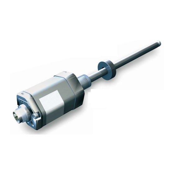
  • Seite 17: Aufbau Und Funktion

    Die Wegaufnehmer mit Ø 10,2 mm und 12,7 mm besitzen am Stabende ein zusätzliches Gewinde zum Abstützen bei großen Nennlängen. Positionsgeber: Definiert die zu messende Position auf dem Wellenleiter. Positionsgeber sind in unterschiedlichen Bauformen lieferbar und gesondert zu bestellen (siehe Zubehör auf Seite 27). www.balluff.com deutsch...
  • Seite 18: Funktion

    BTL7-A/E501-M _ _ _ _ -A/B/CD/Y/Z(8)-NEX-S32/KA _ _ Zündschutzart Micropulse Wegaufnehmer - Bauform Stab „nA“ und „tb“ Aufbau und Funktion (Fortsetzung) Funktion LED-Anzeige Im Micropulse Wegaufnehmer befindet sich der Wellenlei- LED 1 LED 2 ter, geschützt durch ein Edelstahlrohr. Entlang des Wellen- leiters wird ein Positionsgeber bewegt. Dieser Positionsge- ber ist mit dem Anlagenbauteil verbunden, dessen Position bestimmt werden soll.
  • Seite 19: Einbau Und Anschluss

    13 mm 8 mm mindestens 11 mm 12,7 mm mindestens 18 mm Tab. 4-1: Bohrungsdurchmesser bei Einbau in einen Hydraulik- zylinder 2.4+0.4 Bild 4-5: Einschraubloch M22×1.5 nach ISO 6149 O-Ring 19.3×2.2 Positionsgeber: Für den Wegaufnehmer BTL7 stehen unterschiedliche Positionsgeber zur Verfügung (siehe Zubehör auf Seite 27). www.balluff.com deutsch...
  • Seite 20: Wegaufnehmer Einbauen

    BTL7-A/E501-M _ _ _ _ -A/B/CD/Y/Z(8)-NEX-S32/KA _ _ Zündschutzart Micropulse Wegaufnehmer - Bauform Stab „nA“ und „tb“ Einbau und Anschluss (Fortsetzung) Wegaufnehmer einbauen Das Gleitelement kann aufgeschraubt oder aufgeklebt werden. ► Schraube gegen Lösen oder Verlieren sichern. ACHTUNG ► Geeigneten Klebstoff auswählen. Funktionsbeeinträchtigung Gleitfläche Unsachgemäße Montage kann die Funktion des Wegauf- Durchflussspalt Kolbenstange...
  • Seite 21: Elektrischer Anschluss

    Kabelausführung: Wegaufnehmerseitig ist der Kabel- BTL7-A max. 30 m schirm mit dem Gehäuse verbunden. BTL7-E max. 100 m Steuerungsseitig den Kabelschirm erden (mit dem Schutzleiter verbinden). 1) Voraussetzung: durch Aufbau, Schirmung und Verlegung keine Einwir- kung fremder Störfelder. Tab. 4-3: Kabellängen BTL7 www.balluff.com deutsch...
  • Seite 22: Inbetriebnahme

    BTL7-A/E501-M _ _ _ _ -A/B/CD/Y/Z(8)-NEX-S32/KA _ _ Zündschutzart Micropulse Wegaufnehmer - Bauform Stab „nA“ und „tb“ Inbetriebnahme System in Betrieb nehmen GEFAHR Unkontrollierte Systembewegungen Bei der Inbetriebnahme und wenn die Wegmess- einrichtung Teil eines Regelsystems ist, dessen Parame- ter noch nicht eingestellt sind, kann das System unkon- trollierte Bewegungen ausführen.
  • Seite 23: Konfiguration Mit Dem Micropulse Configuration Tool

    – Wegaufnehmer an Stromversorgung angeschlossen. – Positionsgeber auf Wegaufnehmer. Die PC-Software und das zugehörige Handbuch Positionsgeber und Ausgänge erhalten Sie im Internet unter www.balluff.com. – Ein oder zwei Positionsgeber wählbar (Werkseinstel- lung: ein Positionsgeber) Anschluss der USB-Kommunikationsbox – Zwei Ausgänge unabhängig belegbar Bei den Wegaufnehmern BTL7-A/E…...
  • Seite 24 BTL7-A/E501-M _ _ _ _ -A/B/CD/Y/Z(8)-NEX-S32/KA _ _ Zündschutzart Micropulse Wegaufnehmer - Bauform Stab „nA“ und „tb“ Konfiguration mit dem Micropulse Configuration Tool (Fortsetzung) Kennlinie frei konfigurierbar – Null- und Endpunkte können eingelesen (Teach-In) oder mit der Maus bestimmt werden. – Der Abstand zwischen Nullpunkt und Endpunkt muss mindestens 4 mm betragen.
  • Seite 25: Einstellen Mit Der Einstellvorrichtung

    ► Einstellvorrichtung für eine spätere Verwendung aufbe- wahren. Nullpunkt Endpunkt Kennlinienverlauf Wegaufnehmer Einheit Min.-Wert Nullwert Endwert Max.-Wert Errorwert steigend BTL7-A… −0,5 +10,0 +10,5 +10,5 (Ausgang 1) BTL7-E… 20,0 20,4 fallend BTL7-A… +10,5 +10,0 −0,5 −0,5 (Ausgang 2) BTL7-E… 20,4 20,0 Tab. 7-1: Wertetabelle der Werkseinstellung www.balluff.com deutsch...
  • Seite 26: Übersicht Der Einstellverfahren

    BTL7-A/E501-M _ _ _ _ -A/B/CD/Y/Z(8)-NEX-S32/KA _ _ Zündschutzart Micropulse Wegaufnehmer - Bauform Stab „nA“ und „tb“ Einstellen mit der Einstellvorrichtung (Fortsetzung) ► Positionsgeber in die neue Endposition verschieben. Übersicht der Einstellverfahren ► Neuen Endpunkt durch Drücken der Taster einlesen. ⇒ Der aktuelle Nullpunkt bleibt erhalten. 7.3.1 Teach-in Die detaillierte Vorgehensweise für das Teach-in...
  • Seite 27: Justieren

    Reset sen. ► Durch Drücken der Taster den gewünschten Anfangs- Die detaillierte Vorgehensweise für das Rück- wert einstellen. setzen ist auf Seite 24 beschrieben. Wegaufnehmer auf die Werkseinstellungen zurücksetzen. vorher nachher Neuer Anfangswert Anfangspunkt Bild 7-4: Neuen Anfangswert justieren www.balluff.com deutsch...
  • Seite 28: Teach-In Mit Der Einstellvorrichtung

    BTL7-A/E501-M _ _ _ _ -A/B/CD/Y/Z(8)-NEX-S32/KA _ _ Zündschutzart Micropulse Wegaufnehmer - Bauform Stab „nA“ und „tb“ Teach-in mit der Einstellvorrichtung ACHTUNG Funktionsbeeinträchtigung LED-Anzeige Angezeigte Werte (Beispiel) Das Teach-in während des Betriebs der Anlage kann zu Fehlfunktionen führen. LED1 LED2 bei 0…10 V bei 4…20 mA ►...
  • Seite 29: Justieren Mit Der Einstellvorrichtung

    1 µA erhöht bzw. verringert. Wird ein Taster länger als 1 s gedrückt gehalten, LED grün leuchtend LED 1 und LED 2 grün-rot alternierend blinkend erhöht sich die Schrittweite. LED 1 und LED 2 rot-rot alternierend blinkend www.balluff.com deutsch...
  • Seite 30 BTL7-A/E501-M _ _ _ _ -A/B/CD/Y/Z(8)-NEX-S32/KA _ _ Zündschutzart Micropulse Wegaufnehmer - Bauform Stab „nA“ und „tb“ Justieren mit der Einstellvorrichtung (Fortsetzung) LED-Anzeige Angezeigte Werte (Beispiel) LED1 LED2 bei 0…10 V bei 4…20 mA Endpunkt einstellen ► Positionsgeber an den neuen Endpunkt bringen. 9.89 V 19.13 mA ‚...
  • Seite 31 Ausgang 1 (wechselt mit jedem Umschalten) ⇒ Nach dem Loslassen blinken erneut beide LEDs. ► Mit Anfangspunkt einstellen fortfahren (siehe Seite 21). Legende LED: LED leuchtet nicht LED grün leuchtend LED grün blinkend LED 1 und LED 2 rot-rot alternierend blinkend www.balluff.com deutsch...
  • Seite 32: Rücksetzen Aller Werte Mit Der Einstellvorrichtung (Reset)

    BTL7-A/E501-M _ _ _ _ -A/B/CD/Y/Z(8)-NEX-S32/KA _ _ Zündschutzart Micropulse Wegaufnehmer - Bauform Stab „nA“ und „tb“ Rücksetzen aller Werte mit der Einstellvorrichtung (Reset) ACHTUNG Funktionsbeeinträchtigung Das Rücksetzen aller Werte während des Betriebs der Anlage kann zu Fehlfunktionen führen. ► Die Anlage vor dem Reset außer Betrieb nehmen. Mit der Reset-Funktion können alle Einstellungen auf die Werkseinstellungen zurückgesetzt werden.
  • Seite 33: Technische Daten

    1) Nur Positionsausgabe. Bei Geschwindigkeitsausgabe nächsthöhere Messewertrate (2 ms bzw. 3 ms). Luftfeuchtigkeit < 90 %, nicht betauend 2) Nennlänge = 500 mm, Positions geber in der Mitte des Messbereichs Druckfestigkeit Stab 3) Einzelbestimmung nach Balluff-Werknorm (bei Einbau in 4) Resonanzfrequenzen ausgenommen Hydraulikzylinder) bei Ø 8 mm ≤ 250 bar 5) Voraussetzung ist, dass im Verpolungsfall zwischen GND und 0 V kein...
  • Seite 34: Maße, Gewichte

    BTL7-A/E501-M _ _ _ _ -A/B/CD/Y/Z(8)-NEX-S32/KA _ _ Zündschutzart Micropulse Wegaufnehmer - Bauform Stab „nA“ und „tb“ Technische Daten (Fortsetzung) 11.6 Maße, Gewichte BTL7-...-KA_ _ Kabelmaterial Gehäusematerial Aluminium Kabeldurchmesser max. 7 mm Flanschmaterial Edelstahl zulässiger Biegeradius Stabmaterial Edelstahl feste Verlegung ≥ 35 mm Ausführung Ø Stab Nennlänge Gewicht Wandstärke Gehäusebefestigung Anzugsdrehmoment Stab...
  • Seite 35: Zubehör

    Aluminium Für BTL7-A/E501-… mit S32-Steckverbinder. Lieferumfang: USB-Kommunikationsbox, USB-Kabel, 2 Adapterkabel je ca. 0,3 m, Kurzanleitung. Im Lieferumfang der Positionsgeber BTL7-A-CB01-USB-KA BTL-P-1013-4R, BTL-P-1013-4S, BTL-P-1012-4R enthalten: Für BTL7-A/E501-… mit Kabelanschluss. Lieferumfang: USB-Kommunikationsbox, USB-Kabel, Distanzstück: 8 mm, Material Polyoxymethylen 1 Adapterkabel ca. 0,6 m, Kurzanleitung. (POM) www.balluff.com deutsch...
  • Seite 36: Steckverbinder Und Kabel

    BTL7-A/E501-M _ _ _ _ -A/B/CD/Y/Z(8)-NEX-S32/KA _ _ Zündschutzart Micropulse Wegaufnehmer - Bauform Stab „nA“ und „tb“ Zubehör (Fortsetzung) 12.6 Steckverbinder und Kabel Farbe YE Gelb BKS-S32M-_ _ GY Grau Steckverbinder gerade, konfektioniert PK Rosa M16 nach IEC 130-9, 8-polig RD Rot Unterschiedliche Kabellängen bestellbar, z. B. BKS-S32M-05: Kabellänge 5 m GN Grün BU Blau...
  • Seite 37: Typenschlüssel

    B8 = metrisches Befestigungsgewinde M18x1.5, O-Ring, Stabdurchmesser 8 mm Y8 = Zollgewinde 3/4"-16UNF, O-Ring, Stabdurchmesser 8 mm Z8 = Zollgewinde 3/4"-16UNF, O-Ring, Stabdurchmesser 8 mm CD = metrisches Befestigungsgewinde M22×1.5, O-Ring, Stabdurchmesser 12,7 mm Elektrischer Anschluss: S32 = 8-polig, M16-Stecker nach IEC 130-9 KA05 = Kabel 5 m www.balluff.com deutsch...
  • Seite 38: Anhang

    BTL7-A/E501-M _ _ _ _ -A/B/CD/Y/Z(8)-NEX-S32/KA _ _ Zündschutzart Micropulse Wegaufnehmer - Bauform Stab „nA“ und „tb“ Anhang 14.1 Umrechnung Längeneinheiten 1 mm = 0,0393700787 inch 1 inch = 25,4 mm inch inch 0,03937008 25,4 0,07874016 50,8 0,11811024 76,2 0,15748031 101,6 0,19685039 0,23622047 152,4 0,27559055 177,8 0,31496063 203,2 0,35433071 228,6 0,393700787 Tab. 14-1: Umrechnungstabelle mm-inch Tab.
  • Seite 39 BTL7-A/E501-M _ _ _ _ -A/B/Y/Z(8)-NEX-S32/KA _ _ BTL7-A/E501-M _ _ _ _ -CD-NEX-S32/KA _ _ User's Guide II 3 G Ex nA IIC T4 X II 2 D Ex tb IIIC T135 °C X IP6x english...
  • Seite 40 www.balluff.com...
  • Seite 41 Starting up the system Operating notes Configuration with the Micropulse Configuration Tool Micropulse Configuration Tool Connecting the USB communication box Configuration options Adjust with the calibration device Calibration device Calibration procedure notes Calibration procedure overview 7.3.1 Teach-in 7.3.2 Adjust 7.3.3 Reset www.balluff.com english...
  • Seite 42 BTL7-A/E501-M _ _ _ _ -A/B/CD/Y/Z(8)-NEX-S32/KA _ _ Ignition protection Micropulse Transducer - Rod Style “nA” and “tb” Teach-in with the calibration device Adjust with the calibration device Reset all values with the calibration device (reset) Technical data 11.1 Accuracy 11.2 Ambient conditions 11.3 Supply voltage (external) 11.4 Output 11.5 Communication lines La, Lb 11.6 Dimensions, weights...
  • Seite 43: User Information

    Do not start up the transducer if you do not have a user’s guide in the language of the country where the product will be used. In such cases, please contact BALLUFF. Disposal ► Observe the national regulations for disposal.
  • Seite 44: Atex Safety Notes

    EN 61000-4-3 Severity level 3 set-up. Flawless function is ensured only when using – Electrical fast transients (burst) original BALLUFF accessories. Use of any other EN 61000-4-4 Severity level 3 components will void the warranty. – Surge EN 61000-4-5 Severity level 2...
  • Seite 45: Use And Inspection

    The flange and housing are mechanically fixed with non-conductive dusts and flammable fibers. electrically conductive connections, so that no potential differences can occur between them. The cable shield is connected to the housing and must be connected to the potential of the system’s control cabinet. www.balluff.com english...
  • Seite 46: Connectors And Magnets

    Drag chains may not be used. Only service technicians from BALLUFF GmbH may repair The open line ends are to be connected outside the defective transducers. Intervention in the product by the classified zones or inside an approved housing.
  • Seite 47: Construction And Function

    Magnet: Defines the position to be measured on the waveguide. Magnets are available in various models and must be ordered separately (see Accessories on page 27). www.balluff.com english...
  • Seite 48: Function

    BTL7-A/E501-M _ _ _ _ -A/B/CD/Y/Z(8)-NEX-S32/KA _ _ Ignition protection Micropulse Transducer - Rod Style “nA” and “tb” Construction and function (continued) Function LED display The Micropulse Transducer contains the waveguide which LED 1 LED 2 is protected by an outer stainless steel tube (rod). A magnet is moved along the waveguide.
  • Seite 49: Installation And Connection

    At least 11 mm 12.7 mm At least 18 mm Tab. 4-1: Bore diameter if installed in a hydraulic cylinder 2.4+0.4 Fig. 4-5: Mounting hole M22×1.5 per ISO 6149 O-ring 19.3×2.2 Magnet: Various magnets are available for the BTL7 transducer (see Accessories on page 27). www.balluff.com english...
  • Seite 50: Installing The Transducer

    BTL7-A/E501-M _ _ _ _ -A/B/CD/Y/Z(8)-NEX-S32/KA _ _ Ignition protection Micropulse Transducer - Rod Style “nA” and “tb” Installation and connection (continued) The slide element can be screwed on or bonded. Installing the transducer ► Secure the screws so they cannot be loosened or lost. ►...
  • Seite 51: Electrical Connection

    Ground the cable shielding on the controller side 1) Prerequisite: Construction, shielding and routing preclude the effect of (connect with the protective earth conductor). any external noise fields. Tab. 4-3: Cable lengths BTL7 www.balluff.com english...
  • Seite 52: Startup

    BTL7-A/E501-M _ _ _ _ -A/B/CD/Y/Z(8)-NEX-S32/KA _ _ Ignition protection Micropulse Transducer - Rod Style “nA” and “tb” Startup Starting up the system DANGER Uncontrolled system movement When starting up, if the position measuring system is part of a closed loop system whose parameters have not yet been set, the system may perform uncontrolled movements.
  • Seite 53: Configuration With The Micropulse Configuration Tool

    – Demo mode without having transducer connected Configuration options The PC software and associated manual can be Prerequisites found in the Internet under www.balluff.com. – Software correctly installed. – USB communication box connected to the transducer Connecting the USB communication box and PC.
  • Seite 54 BTL7-A/E501-M _ _ _ _ -A/B/CD/Y/Z(8)-NEX-S32/KA _ _ Ignition protection Micropulse Transducer - Rod Style “nA” and “tb” Configuration with the Micropulse Configuration Tool (continued) Freely configurable curve – Null and end points can be read (teach-in) or specified with the mouse. – The distance between the null point and end point must be at least 4 mm.
  • Seite 55: Adjust With The Calibration Device

    Linear Unit Min. value Null value End value Max. value Error transducer value Rising (output 1) BTL7-A… −0.5 +10.0 +10.5 +10.5 BTL7-E… 20.0 20.4 Falling (output 2) BTL7-A… +10.5 +10.0 −0.5 −0.5 BTL7-E… 20.4 20.0 Tab. 7-1: Factory settings value table www.balluff.com english...
  • Seite 56: Calibration Procedure Overview

    BTL7-A/E501-M _ _ _ _ -A/B/CD/Y/Z(8)-NEX-S32/KA _ _ Ignition protection Micropulse Transducer - Rod Style “nA” and “tb” Adjust with the calibration device (continued) ► Move magnet to the new end position. Calibration procedure overview ► Read new end point by pressing the buttons. ⇒...
  • Seite 57: Adjust

    ► Set the new start value by pressing the buttons. 7.3.3 Reset The detailed procedure for the reset is described on page 24. Restoring the transducer to its factory settings. Before After New start value Start point Fig. 7-4: Adjust a new start value www.balluff.com english...
  • Seite 58: Teach-In With The Calibration Device

    BTL7-A/E501-M _ _ _ _ -A/B/CD/Y/Z(8)-NEX-S32/KA _ _ Ignition protection Micropulse Transducer - Rod Style “nA” and “tb” Teach-in with the calibration device NOTICE Interference in function LED display Displayed values (example) Teach-in while the system is running may result in malfunctions. LED1 LED2 At 0…10 V At 4…20 mA ►...
  • Seite 59: Adjust With The Calibration Device

    1 mV or 1 µA. If a button is held down longer than 1 s, the step LED green LED 1 and LED 2 flashing green-red in alternation interval is increased. LED 1 and LED 2 flashing red-red in alternation www.balluff.com english...
  • Seite 60 BTL7-A/E501-M _ _ _ _ -A/B/CD/Y/Z(8)-NEX-S32/KA _ _ Ignition protection Micropulse Transducer - Rod Style “nA” and “tb” Adjust with the calibration device (continued) LED display Displayed values (example) LED1 LED2 At 0…10 V At 4…20 mA Set end point ► Bring magnet to the new end point. 9.89 V 19.13 mA ‚...
  • Seite 61 ⇒ Both LEDs will flash again once the buttons are released. ► Continue with Set start point (see page 21). LED legend: LED not on LED green LED flashing green LED 1 and LED 2 flashing red-red in alternation www.balluff.com english...
  • Seite 62: Reset All Values With The Calibration Device (Reset)

    BTL7-A/E501-M _ _ _ _ -A/B/CD/Y/Z(8)-NEX-S32/KA _ _ Ignition protection Micropulse Transducer - Rod Style “nA” and “tb” Reset all values with the calibration device (reset) NOTICE Interference in function Resetting all values while the system is running may result in malfunctions. ► Stop the system before performing the reset. The reset function can be used to restore all the settings to the factory settings.
  • Seite 63: Technical Data

    (2 ms or 3 ms). Relative humidity < 90%, non-condensing 2) Nominal length = 500 mm, magnet in the center of the measuring range Rod pressure rating 3) Individual specifications as per Balluff factory standard (when installed in hydraulic 4) Resonant frequencies excluded cylinders) For Ø 8 mm ≤ 250 bar...
  • Seite 64: Dimensions, Weights

    BTL7-A/E501-M _ _ _ _ -A/B/CD/Y/Z(8)-NEX-S32/KA _ _ Ignition protection Micropulse Transducer - Rod Style “nA” and “tb” Technical data (continued) 11.6 Dimensions, weights BTL7-…-KA_ _ Cable material Housing material Aluminum Cable diameter Max. 7 mm Flange material Stainless steel Permissible bending Rod material Stainless steel radius Fixed routing ≥ 35 mm...
  • Seite 65: Accessories

    Included in the scope of delivery for the 2 adapter cables each approx. 0.3 m, condensed guide. BTL-P-1013-4R, BTL-P-1013-4S, BTL-P-1012-4R: BTL7-A-CB01-USB-KA Spacer: 8 mm, material: polyoxymethylene For BTL7-A/E501-… with cable connection (POM) Scope of delivery: USB communication box, USB cable, 1 adapter cable approx. 0.6 m, condensed guide. www.balluff.com english...
  • Seite 66: Connectors And Cables

    BTL7-A/E501-M _ _ _ _ -A/B/CD/Y/Z(8)-NEX-S32/KA _ _ Ignition protection Micropulse Transducer - Rod Style “nA” and “tb” Accessories (continued) 12.6 Connectors and cables Color YE yellow BKS-S32M-_ _ GY gray Straight connector, preassembled PK pink M16 per IEC 130-9, 8-pin RD red Various cable lengths can be ordered, e.g. BKS-S32M-05: Cable length 5 m GN green BU blue...
  • Seite 67: Type Code Breakdown

    Y8 = 3/4”-16UNF thread, O-ring, rod diameter 8 mm Z8 = 3/4"-16UNF thread, O-ring, rod diameter 8 mm CD = Metric mounting thread M22×1.5, O-ring, rod diameter 12.7 mm Electrical connection: S32 = 8-pin, M16 plug per IEC 130-9 KA05 = Cable, 5 m www.balluff.com english...
  • Seite 68: Appendix

    BTL7-A/E501-M _ _ _ _ -A/B/CD/Y/Z(8)-NEX-S32/KA _ _ Ignition protection Micropulse Transducer - Rod Style “nA” and “tb” Appendix 14.1 Converting units of length 1 mm = 0.0393700787 inches 1 inch = 25.4 mm inch inch 0.03937008 25.4 0.07874016 50.8 0.11811024 76.2 0.15748031 101.6 0.19685039 0.23622047 152.4 0.27559055 177.8 0.31496063 203.2 0.35433071 228.6 0.393700787 Tab.
  • Seite 69 BTL7-A/E501-M _ _ _ _ -A/B/Y/Z(8)-NEX-S32/KA _ _ BTL7-A/E501-M _ _ _ _ -CD-NEX-S32/KA _ _ Notice d’utilisation II 3 G Ex nA IIC T4 X II 2 D Ex tb IIIC T135 °C X IP6x français...
  • Seite 70 www.balluff.com...
  • Seite 71 Micropulse Configuration Tool Raccordement du module de communication USB Possibilités de configuration Réglage à l’aide du dispositif de réglage Dispositif de réglage Remarques concernant la procédure de réglage Aperçu des procédures de réglage 7.3.1 Apprentissage 7.3.2 Ajustage 7.3.3 Réinitialisation ("Reset") www.balluff.com français...
  • Seite 72 BTL7-A/E501-M _ _ _ _ -A/B/CD/Y/Z(8)-NEX-S32/KA _ _ Types de protection Capteur de déplacement Micropulse - Forme à tige contre l’inflammation « nA » et « tb » Apprentissage à l’aide du dispositif de réglage Ajustage à l’aide du dispositif de réglage Réinitialisation de l’ensemble des valeurs ("Reset") à l’aide du dispositif de réglage 24 Caractéristiques techniques 11.1 Précision 11.2 Conditions ambiantes...
  • Seite 73: Informations À L'intention De L'utilisateur

    Respecter impérativement les avertissements de cette appareil est téléchargeable dans l’espace de notice et les mesures décrites pour éviter tout danger. téléchargement sur www.balluff.com. Pour cela, saisir la désignation du type ou la symboli‑ Les avertissements utilisés comportent différents mots‑clés sation commerciale dans le masque de recher‑...
  • Seite 74: Consignes De Sécurité Atex

    La condition préalable au bon fonctionnement du capteur est l’utilisation d’accessoires d’origine – Surtensions transitoires (Surge) Degré de BALLUFF ; l’utilisation d’autres composants entraîne la EN 61000‑4‑5 sévérité 2 nullité de la garantie. – Grandeurs perturbatrices véhiculées par câble, induites par des champs L’exploitant de la machine ou de l’installation doit s’assurer...
  • Seite 75: Utilisation Et Contrôle

    électroconducteur fixe. Le câble poussiéreuse explosible, aussi bien avec des poussières blindé est relié au boîtier et doit être posé sur le potentiel conductrices et non conductrices qu’avec des peluches de l’armoire électrique de l’installation. inflammables. www.balluff.com français...
  • Seite 76: Connecteurs Et Capteurs De Position

    La réparation de capteurs de déplacement défectueux ne d’entraînement n’est pas autorisée. doit être effectuée que par des techniciens de maintenance de la société BALLUFF GmbH. Pour des Les extrémités ouvertes de câbles doivent être raccordées raisons de sécurité, toute intervention par l’exploitant est en dehors de la classification par zones ou à...
  • Seite 77: Structure Et Fonction

    Capteur de position : définit la position à mesurer sur le guide d’ondes. Les capteurs de position peuvent être fournis sous différentes formes et doivent par conséquent être commandés séparément (voir Accessoires, page 27). www.balluff.com français...
  • Seite 78: Fonction

    BTL7-A/E501-M _ _ _ _ -A/B/CD/Y/Z(8)-NEX-S32/KA _ _ Types de protection Capteur de déplacement Micropulse - Forme à tige contre l’inflammation « nA » et « tb » Structure et fonction (suite) Fonction Affichage à LED Le capteur de déplacement Micropulse abrite le guide LED 1 LED 2 d’ondes, qui est protégé par un tube en acier inoxydable. Un capteur de position se déplace le long du guide d’ondes.
  • Seite 79: Montage Et Raccordement

    Tab. 4‑1 : Diamètre de perçage en cas de montage dans un vérin hydraulique 2.4+0.4 Fig. 4‑5 : Trou de vissage M22×1.5 selon ISO 6149, joint torique 19.3×2.2 Capteur de position : différents modèles de capteurs de position sont disponibles pour le capteur de déplacement BTL7 (voir Accessoires, page 27). www.balluff.com français...
  • Seite 80: Montage Du Capteur De Déplacement

    BTL7-A/E501-M _ _ _ _ -A/B/CD/Y/Z(8)-NEX-S32/KA _ _ Types de protection Capteur de déplacement Micropulse - Forme à tige contre l’inflammation « nA » et « tb » Montage et raccordement (suite) L’élément coulissant peut être vissé ou collé. Montage du capteur de déplacement ► Sécuriser les vis contre le desserrage ou la perte. ►...
  • Seite 81: Raccordement Électrique

    Il doit être mis à la terre du côté commande (relié au fil BTL7‑E Max. 100 m de terre). 1) Condition préalable : la structure, le blindage et le câblage excluent toute influence de champs perturbateurs externes. Tab. 4‑3 : Longueurs de câble BTL7 www.balluff.com français...
  • Seite 82: 14 5.2 Conseils D'utilisation

    BTL7-A/E501-M _ _ _ _ -A/B/CD/Y/Z(8)-NEX-S32/KA _ _ Types de protection Capteur de déplacement Micropulse - Forme à tige contre l’inflammation « nA » et « tb » Mise en service Mise en service du système DANGER Mouvements incontrôlés du système Lors de la mise en service et lorsque le système de mesure de déplacement fait partie intégrante d’un système de régulation dont les paramètres n’ont pas encore été...
  • Seite 83: Configuration Avec Micropulse Configuration Tool

    Le logiciel PC ainsi que le manuel déplacement. correspondant sont disponibles sur notre site Capteur de position et sorties Internet www.balluff.com. – Au choix, un ou deux capteur(s) de position (réglage usine : un capteur de position) Raccordement du module de communication –...
  • Seite 84 BTL7-A/E501-M _ _ _ _ -A/B/CD/Y/Z(8)-NEX-S32/KA _ _ Types de protection Capteur de déplacement Micropulse - Forme à tige contre l’inflammation « nA » et « tb » Configuration avec Micropulse Configuration Tool (suite) Courbe à configuration libre – Le point zéro et la fin de plage peuvent être relevés (apprentissage) ou déterminés à...
  • Seite 85: Réglage À L'aide Du Dispositif De Réglage

    Valeur min. Valeur zéro Valeur Valeur max. Valeur déplacement finale d’erreur Croissante (sortie 1) BTL7‑A… −0,5 +10,0 +10,5 +10,5 BTL7‑E… 20,0 20,4 Décroissante BTL7‑A… +10,5 +10,0 −0,5 −0,5 (sortie 2) BTL7‑E… 20,4 20,0 Tab. 7‑1 : Tableau de valeurs du réglage usine www.balluff.com français...
  • Seite 86: Aperçu Des Procédures De Réglage

    BTL7-A/E501-M _ _ _ _ -A/B/CD/Y/Z(8)-NEX-S32/KA _ _ Types de protection Capteur de déplacement Micropulse - Forme à tige contre l’inflammation « nA » et « tb » Réglage à l’aide du dispositif de réglage (suite) ► Déplacer le capteur de position sur la nouvelle fin de Aperçu des procédures de réglage plage.
  • Seite 87: Ajustage

    ► En appuyant sur les boutons, régler la valeur initiale souhaitée. La procédure détaillée pour la réinitialisation est décrite à la page 24. Réinitialisation aux réglages d’usine du capteur de déplacement. Avant Après Nouvelle valeur initiale Point initial Fig. 7‑4 : Ajustage de la nouvelle valeur initiale www.balluff.com français...
  • Seite 88 BTL7-A/E501-M _ _ _ _ -A/B/CD/Y/Z(8)-NEX-S32/KA _ _ Types de protection Capteur de déplacement Micropulse - Forme à tige contre l’inflammation « nA » et « tb » Apprentissage à l’aide du dispositif de réglage ATTENTION Limitations de fonctionnement Affichage Valeurs affichées (exemple) L’apprentissage pendant le fonctionnement de à...
  • Seite 89 LED éteinte est augmentée ou diminuée d’env. 1 mV ou 1 µA. Si un bouton est maintenu enfoncé pendant plus LED 1 et LED 2 clignotant alternativement en d’1 s, l’incrément augmente. LED allumée en vert vert‑rouge LED 1 et LED 2 clignotant alternativement en rouge‑rouge www.balluff.com français...
  • Seite 90 BTL7-A/E501-M _ _ _ _ -A/B/CD/Y/Z(8)-NEX-S32/KA _ _ Types de protection Capteur de déplacement Micropulse - Forme à tige contre l’inflammation « nA » et « tb » Ajustage à l’aide du dispositif de réglage (suite) Affichage Valeurs affichées (exemple) à LED avec avec LED1 LED2 0 … 10 V 4 …...
  • Seite 91 ⇒ Les deux LED clignotent à nouveau après relâchement des boutons. ► Poursuivre avec le réglage du point initial (voir page 21). Légende LED : LED éteinte LED allumée en vert LED 1 et LED 2 clignotant alternativement en LED clignotant en vert rouge‑rouge www.balluff.com français...
  • Seite 92 BTL7-A/E501-M _ _ _ _ -A/B/CD/Y/Z(8)-NEX-S32/KA _ _ Types de protection Capteur de déplacement Micropulse - Forme à tige contre l’inflammation « nA » et « tb » Réinitialisation de l’ensemble des valeurs ("Reset") à l’aide du dispositif de réglage ATTENTION Limitations de fonctionnement La réinitialisation de l’ensemble des valeurs pendant le fonctionnement de l’installation peut donner lieu à...
  • Seite 93: Caractéristiques Techniques

    2) Longueur nominale = 500 mm, capteur de position au milieu de la plage dans un vérin hydraulique) de mesure pour Ø 8 mm ≤ 250 bar 3) Détermination individuelle selon la norme d’usine Balluff pour Ø 10,2 mm ≤ 600 bar 4) Exception faite des fréquences de résonance pour Ø 12,7 mm ≤ 1000 bar...
  • Seite 94 BTL7-A/E501-M _ _ _ _ -A/B/CD/Y/Z(8)-NEX-S32/KA _ _ Types de protection Capteur de déplacement Micropulse - Forme à tige contre l’inflammation « nA » et « tb » Caractéristiques techniques (suite) 11.6 Dimensions, poids BTL7-…-KA_ _ Matériau du câble Matériau du boîtier Aluminium Diamètre de câble Max. 7 mm Matériau du bride Acier inoxydable Rayon de courbure Matériau de la tige...
  • Seite 95: Ecrous De Fixation

    Matériel livré avec les capteurs de position 2 câbles d’adaptation de chacun 0,3 m, notice résumée. BTL-P-1013-4R, BTL-P-1013-4S, BTL-P-1012-4R : BTL7-A-CB01-USB-KA Bague d’écartement : 8 mm, polyoxyméthylène (POM) Pour BTL7‑A/E501‑… avec câble de raccordement. Matériel livré : module de communication USB, câble USB, 1 câble d’adaptation d’env. 0,6 m, notice résumée. www.balluff.com français...
  • Seite 96: Connecteurs Et Câbles

    BTL7-A/E501-M _ _ _ _ -A/B/CD/Y/Z(8)-NEX-S32/KA _ _ Types de protection Capteur de déplacement Micropulse - Forme à tige contre l’inflammation « nA » et « tb » Accessoires (suite) 12.6 Connecteurs et câbles Broche Couleur YE jaune BKS-S32M-_ _ GY gris Connecteur droit, confectionné PK rose M16 selon IEC 130‑9, 8 pôles RD rouge Différentes longueurs de câble disponibles, p. ex.
  • Seite 97 Z8 = filetage au pouce 3/4"‑16UNF, joint torique, diamètre de tige 8 mm CD = filetage de fixation métrique M22×1.5, joint torique, diamètre de tige 12,7 mm Raccordement électrique : S32 = 8 pôles, connecteur M16 selon IEC 130‑9 KA05 = câble 5 m www.balluff.com français...
  • Seite 98: Conversion Unités De Longueur

    BTL7-A/E501-M _ _ _ _ -A/B/CD/Y/Z(8)-NEX-S32/KA _ _ Types de protection Capteur de déplacement Micropulse - Forme à tige contre l’inflammation « nA » et « tb » Annexe 14.1 Conversion unités de longueur 1 mm = 0,0393700787 pouce 1 pouce = 25,4 mm pouce pouce 0,03937008 25,4 0,07874016 50,8 0,11811024 76,2 0,15748031 101,6 0,19685039 0,23622047 152,4 0,27559055 177,8...
  • Seite 99 BTL7-A/E501-M _ _ _ _ -A/B/Y/Z(8)-NEX-S32/KA _ _ BTL7-A/E501-M _ _ _ _ -CD-NEX-S32/KA _ _ Manuale d’uso II 3 G Ex nA IIC T4 X II 2 D Ex tb IIIC T135 °C X IP6x Italiano...
  • Seite 100 www.balluff.com...
  • Seite 101 Configurazione con il Micropulse Configuration Tool Micropulse Configuration Tool Collegamento della scatola di comunicazione USB Possibilità di configurazione Impostazione con il dispositivo di regolazione Dispositivo di regolazione Avvertenze sulla procedura di regolazione Prospetto delle procedure di regolazione 7.3.1 Teach-in 7.3.2 Calibrazione 7.3.3 Reset www.balluff.com italiano...
  • Seite 102 BTL7-A/E501-M _ _ _ _ -A/B/CD/Y/Z(8)-NEX-S32/KA _ _ Tipo di protezione Trasduttore di posizione Micropulse - versione a barra dall’accensione “nA” e “tb” Teach-in con dispositivo di regolazione Calibrazione con il dispositivo di regolazione Ripristino di tutti i valori con il dispositivo di regolazione (Reset) Dati tecnici 11.1 Precisione 11.2 Condizioni ambientali...
  • Seite 103: Informazioni Utente

    Seguire scrupolosamente le avvertenze di sicurezza in apparecchio è disponibile nell'area di download queste istruzioni e le misure descritte per evitare pericoli. del sito www.balluff.com. Allo scopo immet- tere la denominazione del tipo o il codice Le avvertenze di sicurezza utilizzate contengono diverse d’ordine nel campo di ricerca.
  • Seite 104: Indicazioni Di Sicurezza Atex

    3 – Impulsi di disturbo transienti rapidi Una prerogativa per il funzionamento corretto è l’uso di (burst) accessori originali BALLUFF, l’uso di altri componenti EN 61000-4-4 Grado di comporta l’esclusione della responsabilità. definizione 3 –...
  • Seite 105: Impiego E Verifica

    La flangia e l’alloggiamento lanugine infiammabile. sono fissati meccanicamente e a conducibilità elettrica per evitare che si verifichino differenze di potenziale. La schermatura del cavo è collegata al corpo e deve essere calibrata in base al potenziale dell’armadio elettrico. www.balluff.com italiano...
  • Seite 106: Connettore E Datore Di Posizione

    La riparazione di un trasduttore di posizione difettoso deve traino non è consentito. essere eseguita esclusivamente dai tecnici dell’assistenza di BALLUFF GmbH. Per motivi di sicurezza non è Le estremità dei cavi aperte devono essere collegate permesso un intervento da parte del gestore.
  • Seite 107: Struttura E Funzione

    Datore di posizione: definisce la posizione da misurare sulla guida d’onda. I datori di posizione sono disponibili in varie tipologie costruttive e devono essere ordinati separatamente (vedere Accessori a pagina 27). www.balluff.com italiano...
  • Seite 108: Funzionamento

    BTL7-A/E501-M _ _ _ _ -A/B/CD/Y/Z(8)-NEX-S32/KA _ _ Tipo di protezione Trasduttore di posizione Micropulse - versione a barra dall’accensione “nA” e “tb” Struttura e funzione (continua) Funzionamento Display LED Nel trasduttore di posizione Micropulse si trova la guida LED 1 LED 2 d’onda, protetta da un tubo in acciaio inox. Lungo la guida d’onda viene spostato un datore di posizione.
  • Seite 109: Montaggio E Collegamento

    Diametro del foro nel montaggio in un cilindro idraulico 2.4+0.4 Fig. 4-5: Foro di avvitamento M22x1.5 secondo ISO 6149 O-ring 19.3x2.2 Datore di posizione: per il trasduttore di posizione BTL7 sono a disposizione diversi datori di posizione (ved. Accessori a pagina 27). www.balluff.com italiano...
  • Seite 110: Montaggio Del Trasduttore Di Posizione

    BTL7-A/E501-M _ _ _ _ -A/B/CD/Y/Z(8)-NEX-S32/KA _ _ Tipo di protezione Trasduttore di posizione Micropulse - versione a barra dall’accensione “nA” e “tb” Montaggio e collegamento (continua) L’elemento scorrevole può essere avvitato o incollato. Montaggio del trasduttore di posizione ► Assicurarsi che le viti non si allentino o vadano perse. ►...
  • Seite 111: Collegamento Elettrico

    Collegare a terra (collegare al conduttore di terra) la 1) Premessa: la struttura, la schermatura e la posa devono essere tali da schermatura del cavo lato unità di controllo. impedire l’influenza di campi di disturbo esterni. Tab. 4-3: Lunghezza cavi BTL7 www.balluff.com italiano...
  • Seite 112: Messa In Funzione

    BTL7-A/E501-M _ _ _ _ -A/B/CD/Y/Z(8)-NEX-S32/KA _ _ Tipo di protezione Trasduttore di posizione Micropulse - versione a barra dall’accensione “nA” e “tb” Messa in funzione Messa in funzione del sistema PERICOLO Movimenti incontrollati del sistema Durante la messa in funzione e se il dispositivo di misura della corsa fa parte di un sistema di regolazione i cui parametri non sono ancora stati impostati, il sistema può...
  • Seite 113: Configurazione Con Il Micropulse Configuration Tool

    Per il software PC ed il manuale relativo – Datore di posizione sul trasduttore di posizione. consultare in Internet l’indirizzo www.balluff.com. Datore di posizione e uscite – Uno o due datori di posizione selezionabili Collegamento della scatola di comunicazione (impostazioni di fabbrica: un datore di posizione) –...
  • Seite 114 BTL7-A/E501-M _ _ _ _ -A/B/CD/Y/Z(8)-NEX-S32/KA _ _ Tipo di protezione Trasduttore di posizione Micropulse - versione a barra dall’accensione “nA” e “tb” Configurazione con il Micropulse Configuration Tool (continua) Curva caratteristica configurabile a piacere – I punti zero e i punti finali possono essere rilevati (Teach-In) o indicati con il mouse.
  • Seite 115: Impostazione Con Il Dispositivo Di Regolazione

    Valore Valore max. Valore di curva posizione finale errore caratteristica ascendente BTL7-A… −0,5 +10,0 +10,5 +10,5 (uscita 1) BTL7-E… 20,0 20,4 discendente BTL7-A… +10,5 +10,0 −0,5 −0,5 (uscita 2) BTL7-E… 20,4 20,0 Tab. 7-1: Tabella valori delle impostazioni di fabbrica www.balluff.com italiano...
  • Seite 116: Prospetto Delle Procedure Di Regolazione

    BTL7-A/E501-M _ _ _ _ -A/B/CD/Y/Z(8)-NEX-S32/KA _ _ Tipo di protezione Trasduttore di posizione Micropulse - versione a barra dall’accensione “nA” e “tb” Impostazione con il dispositivo di regolazione (continua) ► Spostare il datore di posizione nella nuova posizione Prospetto delle procedure di regolazione finale.
  • Seite 117: Calibrazione

    ► Impostare il valore iniziale desiderato premendo i tasti. 7.3.3 Reset La procedura dettagliata di ripristino è descritta a pagina 24. Riportare il trasduttore di posizione alle impostazioni di fabbrica. precedente successivo Nuovo valore iniziale Punto iniziale Fig. 7-4: Calibrare il nuovo valore iniziale www.balluff.com italiano...
  • Seite 118 BTL7-A/E501-M _ _ _ _ -A/B/CD/Y/Z(8)-NEX-S32/KA _ _ Tipo di protezione Trasduttore di posizione Micropulse - versione a barra dall’accensione “nA” e “tb” Teach-in con dispositivo di regolazione ATTENZIONE Anomalie funzionali Display LED Valori indicati (esempio) Effettuando la procedura di Teach-in durante il funzionamento dell’impianto, potrebbero verificarsi malfunzionamenti.
  • Seite 119 1 mV oppure 1 µA. Mantenendo premuto un tasto per oltre 1 s, aumenta LED 1 e LED 2 verde-rosso, lampeggianti l’incremento del passo. LED verde, luce fissa alternativamente LED 1 e LED 2 rosso-rosso, lampeggianti alternativamente www.balluff.com italiano...
  • Seite 120 BTL7-A/E501-M _ _ _ _ -A/B/CD/Y/Z(8)-NEX-S32/KA _ _ Tipo di protezione Trasduttore di posizione Micropulse - versione a barra dall’accensione “nA” e “tb” Calibrazione con il dispositivo di regolazione (continua) Display LED Valori indicati (esempio) LED1 LED2 a 0…10 V a 4…20 mA Regolazione del punto finale 9.89 V 19.13 mA ►...
  • Seite 121 ⇒ Dopo aver rilasciato i tasti entrambi i LED lampeggiano di nuovo. ► Procedere con la regolazione del punto iniziale (vedere pagina 21). Legenda LED: LED spento LED verde, luce fissa LED 1 e LED 2 rosso-rosso, lampeggianti LED verde lampeggiante alternativamente www.balluff.com italiano...
  • Seite 122 BTL7-A/E501-M _ _ _ _ -A/B/CD/Y/Z(8)-NEX-S32/KA _ _ Tipo di protezione Trasduttore di posizione Micropulse - versione a barra dall’accensione “nA” e “tb” Ripristino di tutti i valori con il dispositivo di regolazione (Reset) ATTENZIONE Anomalie funzionali Effettuando la procedura di reset di tutti i valori durante il funzionamento dell’impianto, potrebbero verificarsi malfunzionamenti.
  • Seite 123: Tensione Di Alimentazione (Esterna)

    Resistenza alla pressione 2) Lunghezza nominale = 500 mm, datore di posizione al centro del campo della barra (per il montaggio di misura in cilindri idraulici) 3) Rilevazione singola secondo la norma interna Balluff con Ø 8 mm ≤ 250 bar 4) Frequenze di risonanza escluse con Ø 10,2 mm ≤ 600 bar...
  • Seite 124 BTL7-A/E501-M _ _ _ _ -A/B/CD/Y/Z(8)-NEX-S32/KA _ _ Tipo di protezione Trasduttore di posizione Micropulse - versione a barra dall’accensione “nA” e “tb” Dati tecnici (continua) 11.6 Dimensioni, pesi BTL7-…-KA_ _ Materiale corpo profilato alluminio Materiale cavo Materiale flangia acciaio inox Diametro del cavo max. 7 mm Materiale barra acciaio inox Raggio di curvatura...
  • Seite 125: Dado Di Fissaggio

    BTL-P-1013-4R, BTL-P-1013-4S, BTL-P-1012-4R: 2 cavo di adattamento di circa 0,3 m ciascuno, istruzioni in Distanziale: 8 mm, materiale poliossimetilene breve. (POM) BTL7-A-CB01-USB-KA Per BTL7-A/E501-…con collegamento cavo. Fornitura: scatola di comunicazione USB, cavo USB, 1 cavo di adattamento di circa 0,6 m ciascuno, istruzioni in breve. www.balluff.com italiano...
  • Seite 126: Connettori E Cavi

    BTL7-A/E501-M _ _ _ _ -A/B/CD/Y/Z(8)-NEX-S32/KA _ _ Tipo di protezione Trasduttore di posizione Micropulse - versione a barra dall’accensione “nA” e “tb” Accessori (continua) 12.6 Connettori e cavi Colore YE giallo BKS-S32M-_ _ GY grigio Connettore diritto, confezionato PK rosa M16 secondo IEC 130-9, a 8 poli RD rosso È...
  • Seite 127: Legenda Codici Di Identificazione

    Y8 = filettatura in pollici 3/4”-16UNF, O-ring, diametro barra 8 mm Z8 = filettatura in pollici 3/4”-16UNF, O-ring, diametro barra 8 mm CD = filettatura di fissaggio metrica M22x1.5, O-ring, diametro barra 12,7 mm Collegamento elettrico: S32 = connettore M16 a 8 poli secondo IEC 130-9 KA05 = cavo 5 m www.balluff.com italiano...
  • Seite 128: Conversione Delle Unità Di Lunghezza

    BTL7-A/E501-M _ _ _ _ -A/B/CD/Y/Z(8)-NEX-S32/KA _ _ Tipo di protezione Trasduttore di posizione Micropulse - versione a barra dall’accensione “nA” e “tb” Appendice 14.1 Conversione delle unità di lunghezza 1 mm = 0,0393700787 pollici 1 pollice = 25,4 mm pollici pollici 0,03937008 25,4 0,07874016 50,8 0,11811024 76,2 0,15748031 101,6 0,19685039 0,23622047 152,4 0,27559055 177,8...
  • Seite 129 BTL7-A/E501-M _ _ _ _ -A/B/Y/Z(8)-NEX-S32/KA _ _ BTL7-A/E501-M _ _ _ _ -CD-NEX-S32/KA _ _ Manual de instrucciones II 3 G Ex nA IIC T4 X II 2 D Ex tb IIIC T135 °C X IP6x español...
  • Seite 130 www.balluff.com...
  • Seite 131: Tipo De Protección

    Micropulse Configuration Tool Conexión del módulo de comunicación USB Posibilidades de configuración Ajuste con el dispositivo de ajuste Dispositivo de ajuste Indicaciones acerca del proceso de ajuste Vista general de los procedimientos de ajuste 7.3.1 Aprendizaje 7.3.2 Ajuste 7.3.3 Reset www.balluff.com español...
  • Seite 132 BTL7-A/E501-M _ _ _ _ -A/B/CD/Y/Z(8)-NEX-S32/KA _ _ Tipo de protección Transductor de desplazamiento Micropulse - contra ignición forma constructiva de varilla “nA” y “tb” Aprendizaje con el dispositivo de ajuste Ajuste de valores con el dispositivo de ajuste Reposición de todos los valores con el dispositivo de ajuste (reset) Datos técnicos 11.1 Precisión 11.2 Condiciones ambientales...
  • Seite 133: Información Para El Usuario

    Si no se dispone de un manual de instrucciones en el Eliminación de desechos idioma del país de utilización, el transductor de desplazamiento no deberá ponerse en servicio. En ese ► Respete las normas nacionales sobre eliminación de caso, póngase en contacto con BALLUFF. desechos. www.balluff.com español...
  • Seite 134: Indicaciones De Seguridad Atex

    – Impulsos perturbadores transitorios de seguridad y disposiciones válidas. La utilización de rápidos (Burst) Grado de accesorios originales de BALLUFF es requisito para un EN 61000-4-4 severidad 3 funcionamiento óptimo; el uso de otros componentes – Tensiones de impulso (Surge) Grado de provoca la exoneración de responsabilidad.
  • Seite 135: Utilización Y Comprobación

    (tanto con polvo con y sin conductividad al potencial del armario eléctrico de la instalación. eléctrica, como con pelusas inflamables). www.balluff.com español...
  • Seite 136: Conectores Y Sensores De Posición

    BALLUFF GmbH. Por motivos de seguridad no está permitida la intervención del explotador. La protección IP del transductor de desplazamiento debe mantenerse incluso cuando no está...
  • Seite 137: Estructura Y Funcionamiento

    Sensor de posición: define la posición que se ha de medir en el guíaondas. Los sensores de posición están disponibles en diferentes formas constructivas y se deben solicitar por separado (véase Accesorios en la página 27). www.balluff.com español...
  • Seite 138: Función

    BTL7-A/E501-M _ _ _ _ -A/B/CD/Y/Z(8)-NEX-S32/KA _ _ Tipo de protección Transductor de desplazamiento Micropulse - contra ignición forma constructiva de varilla “nA” y “tb” Estructura y funcionamiento (continuación) Función Indicador LED En el transductor de desplazamiento Micropulse se LED 1 LED 2 encuentra el guíaondas, protegido mediante un tubo de acero inoxidable.
  • Seite 139: Montaje Y Conexión

    Diámetro del orificio en caso de montaje en un cilindro hidráulico 2.4+0.4 Fig. 4-5: Agujero roscado M22×1.5 según ISO 6149, junta tórica 19.3×2.2 Sensor de posición: para el transductor de desplazamiento BTL7 hay diferentes sensores de posición disponibles (véase Accesorios en la página 27). www.balluff.com español...
  • Seite 140: Montaje Del Transductor De Desplazamiento

    BTL7-A/E501-M _ _ _ _ -A/B/CD/Y/Z(8)-NEX-S32/KA _ _ Tipo de protección Transductor de desplazamiento Micropulse - contra ignición forma constructiva de varilla “nA” y “tb” Montaje y conexión (continuación) El elemento de deslizamiento se puede atornillar o pegar. Montaje del transductor de desplazamiento ► Asegure el tornillo para que no se suelte o pierda. ►...
  • Seite 141: Conexión Eléctrica

    Conecte a tierra (con el conductor de protección) el blindaje del cable en el lado del control. 1) Requisito: no deben intervenir campos parasitarios externos a consecu- encia del montaje, blindaje y tendido. Tab. 4-3: Longitudes de cable BTL7 www.balluff.com español...
  • Seite 142: Puesta En Servicio

    BTL7-A/E501-M _ _ _ _ -A/B/CD/Y/Z(8)-NEX-S32/KA _ _ Tipo de protección Transductor de desplazamiento Micropulse - contra ignición forma constructiva de varilla “nA” y “tb” Puesta en servicio Puesta en servicio del sistema PELIGRO Movimientos incontrolados del sistema El sistema puede realizar movimientos incontrolados durante la puesta en servicio y si el dispositivo de medición de desplazamiento forma parte de un sistema de regulación cuyos parámetros todavía no se han...
  • Seite 143: Configuración Con La Micropulse Configuration Tool

    El software de PC y el correspondiente manual se pueden obtener en Internet en la página – Seleccionables uno o dos sensores de posición (ajuste www.balluff.com. de fábrica: un sensor de posición) – Dos salidas utilizables independientemente entre sí Conexión del módulo de comunicación USB...
  • Seite 144 BTL7-A/E501-M _ _ _ _ -A/B/CD/Y/Z(8)-NEX-S32/KA _ _ Tipo de protección Transductor de desplazamiento Micropulse - contra ignición forma constructiva de varilla “nA” y “tb” Configuración con la Micropulse Configuration Tool (continuación) Curva característica de libre configuración – Los puntos cero y los puntos finales pueden introducirse por lectura (aprendizaje) o determinarse con el ratón.
  • Seite 145: Ajuste Con El Dispositivo De Ajuste

    Valor máx. Valor de la curva desplazamiento error característica ascendente (salida 1) BTL7-A… −0,5 +10,0 +10,5 +10,5 BTL7-E… 20,0 20,4 descendente BTL7-A… +10,5 +10,0 −0,5 −0,5 (salida 2) BTL7-E… 20,4 20,0 Tab. 7-1: Tabla de valores del ajuste de fábrica www.balluff.com español...
  • Seite 146: Vista General De Los Procedimientos De Ajuste

    BTL7-A/E501-M _ _ _ _ -A/B/CD/Y/Z(8)-NEX-S32/KA _ _ Tipo de protección Transductor de desplazamiento Micropulse - contra ignición forma constructiva de varilla “nA” y “tb” Ajuste con el dispositivo de ajuste (continuación) ► Desplace el sensor de posición a la nueva posición Vista general de los procedimientos de ajuste final.
  • Seite 147: Ajuste

    Reset pulsadores. El procedimiento detallado para la reposición se describe en la página 24. Reponga el transductor de desplazamiento a los ajustes de fábrica. antes después Nuevo valor inicial Punto inicial Fig. 7-4: Ajuste de un valor inicial nuevo www.balluff.com español...
  • Seite 148 BTL7-A/E501-M _ _ _ _ -A/B/CD/Y/Z(8)-NEX-S32/KA _ _ Tipo de protección Transductor de desplazamiento Micropulse - contra ignición forma constructiva de varilla “nA” y “tb” Aprendizaje con el dispositivo de ajuste ATENCIÓN Merma del funcionamiento Indicador Valores indicados (ejemplo) El aprendizaje durante el funcionamiento de la instalación puede provocar funciones erróneas.
  • Seite 149 1 mV o 1 µA. Si un pulsador se acciona durante más de 1 s, el LED 1 y LED 2 intermitentes alternadamente en incremento o la reducción es mayor. LED verde encendido verde-rojo LED 1 y LED 2 intermitentes alternadamente en rojo-rojo www.balluff.com español...
  • Seite 150 BTL7-A/E501-M _ _ _ _ -A/B/CD/Y/Z(8)-NEX-S32/KA _ _ Tipo de protección Transductor de desplazamiento Micropulse - contra ignición forma constructiva de varilla “nA” y “tb” Ajuste de valores con el dispositivo de ajuste (continuación) Indicador Valores indicados (ejemplo) LED 1 LED 2 0…10 V 4…20 mA Ajustar el punto final 9.89 V 19.13 mA ►...
  • Seite 151 ⇒ Los dos LED parpadean de nuevo al soltar. ► Continúe con el ajuste del punto inicial (véase la página 21). Leyenda LED: El LED no se enciende LED verde encendido LED 1 y LED 2 intermitentes alternadamente en LED verde intermitente rojo-rojo www.balluff.com español...
  • Seite 152 BTL7-A/E501-M _ _ _ _ -A/B/CD/Y/Z(8)-NEX-S32/KA _ _ Tipo de protección Transductor de desplazamiento Micropulse - contra ignición forma constructiva de varilla “nA” y “tb” Reposición de todos los valores con el dispositivo de ajuste (reset) ATENCIÓN Merma del funcionamiento La reposición de todos los valores durante el funcionamiento de la instalación puede provocar funciones erróneas.
  • Seite 153: Datos Técnicos

    2) Longitud nominal = 500 mm, sensor de posición en el centro de la zona Resistencia a la presión de la medible varilla (si se monta en un 3) Disposición individual según la norma de fábrica de Balluff cilindro hidráulico) 4) Frecuencias de resonancias excluidas Si Ø 8 mm ≤ 250 bar...
  • Seite 154 BTL7-A/E501-M _ _ _ _ -A/B/CD/Y/Z(8)-NEX-S32/KA _ _ Tipo de protección Transductor de desplazamiento Micropulse - contra ignición forma constructiva de varilla “nA” y “tb” Datos técnicos (continuación) 11.6 Medidas, pesos BTL7-…-KA_ _ Material de cable Material de carcasa Aluminio Diámetro del cable Máx. 7 mm Material de brida Acero inoxidable Radio de flexión admisible...
  • Seite 155: Tuerca De Fijación

    El volumen de suministro de los sensores de instrucciones breves. posición BTL-P-1013-4R, BTL-P-1013-4S, BTL-P-1012-4R incluye: BTL7-A-CB01-USB-KA Elemento 8 mm, material polioximetileno Para BTL7-A/E501-… con conexión de cable. distanciador: (POM) Volumen de suministro: módulo de comunicación USB, cable USB, 1 cable adaptador de aprox. 0,6 m, instrucciones breves. www.balluff.com español...
  • Seite 156: Conectores Y Cables

    BTL7-A/E501-M _ _ _ _ -A/B/CD/Y/Z(8)-NEX-S32/KA _ _ Tipo de protección Transductor de desplazamiento Micropulse - contra ignición forma constructiva de varilla “nA” y “tb” Accesorios (continuación) 12.6 Conectores y cables Color YE amarillo BKS-S32M-_ _ GY gris Conector recto, confeccionado PK rosa M16 según IEC 130-9, 8 polos RD rojo Posibilidad de pedir longitudes de cables distintas, p. ej.
  • Seite 157: Código De Modelo

    Z8 = rosca inglesa 3/4"-16UNF, junta tórica, diámetro de varilla 8 mm CD = rosca de fijación métrica M22×1.5, junta tórica, diámetro de varilla 12,7 mm Conexión eléctrica: S32 = 8 polos, conector M16 según IEC 130-9 KA05 = cable de 5 m www.balluff.com español...
  • Seite 158: Conversión De Unidades De Longitud

    BTL7-A/E501-M _ _ _ _ -A/B/CD/Y/Z(8)-NEX-S32/KA _ _ Tipo de protección Transductor de desplazamiento Micropulse - contra ignición forma constructiva de varilla “nA” y “tb” Anexo 14.1 Conversión de unidades de longitud 1 mm = 0,0393700787 pulgadas 1 pulgada = 25,4 mm pulgadas pulgadas 0,03937008 25,4 0,07874016 50,8 0,11811024 76,2 0,15748031 101,6 0,19685039 0,23622047 152,4...
  • Seite 159 BTL7-A/E501-M _ _ _ _ -A/B/Y/Z(8)-NEX-S32/KA _ _ BTL7-A/E501-M _ _ _ _ -CD-NEX-S32/KA _ _ 使用说明书 II 3 G Ex nA IIC T4 X II 2 D Ex tb IIIC T135 °C X IP6x 中文...
  • Seite 160 www.balluff.com...
  • Seite 161 2.4.3 运营方文档 装配、安装和设置 插拔连接器和位置传感器 维护、检测和维修 结构与功能 结构 功能 LED 显示 安装和连接 安装类型 准备安装 安装位移传感器 4.3.1 液压缸的安装建议 电子接口 4.4.1 插拔连接器 S32 / 电缆接口 KA_ _ 屏蔽与布线 调试运行 系统投入使用 运行说明 使用微脉冲配置工具进行配置 微脉冲配置工具 连接 USB 通信盒 配置方法 使用调节装置设置 调节装置 调节过程提示 调节方法概览 7.3.1 示教功能 7.3.2 校准 7.3.3 复位 中文 www.balluff.com...
  • Seite 162 防爆类型 BTL7-A/E501-M _ _ _ _ -A/B/CD/Y/Z(8)-NEX-S32/KA _ _ 微脉冲位移传感器 – 杆状结构 “nA”和“tb” 使用调节装置示教 使用调节装置校准 使用调节装置复位所有数值(复位) 技术参数 11.1 精度 11.2 环境条件 11.3 供电(外部) 11.4 输出端 11.5 通信线 La、Lb 11.6 尺寸、重量 配件 12.1 用于 BTL7-…-A/B/Y/Z(8)-… 的位置传感器 12.2 用于 BTL7-…-CD-… 的位置传感器 12.3 BTL-P-1028-15R (用于带用于支承管的特种配件) 12.4 固定螺母 12.5 USB 通信盒...
  • Seite 163: 用户信息

    操作顺序按编号进行说明: 章节 2“ATEX 安全提示”包含关于在有爆炸危险区域内使 1. 操作说明 1 用位移传感器的提示和要求。本操作说明书其他章节中包 2. 操作说明 2 含同样适用于未划分区域的范围的额外信息。 提示、建议 供货范围 该符号代表普通提示。 该符号代表调节装置上的按钮。 BTL7 位移传感器 – 调节装置 – 此类符号代表 LED 显示。 操作说明书(包括符合性声明) – 特定设备的符合性声明请参阅 www.balluff.com 的下载区。为此需在搜索栏 警告提示的意义 内输入型号名称或订购代码。 请务必注意说明书中的警告提示和所述避免危险的措施。 可提供各类不同结构的连接插头和位置传感 所用的警告提示包含各种不同的信号词,并按照下列示意 器,因此需要单独订购(参见附件,第 27 图进行构图: 页起)。 信号词 合格人员 危险的种类和来源 本操作说明书的目标人群是具有选择、安装和运行方面必 忽视危险的后果 要知识的专业人士。 ► 防止危险的措施 语言 下列信号词的意义: 德语版本被视为原装说明书。其他语言版本均为原装说明...
  • Seite 164: Atex 安全提示

    ATEX 安全提示 使用规定 该位移传感器满足下列产品标准要求: EN 61326-2-3(抗干扰和辐射) – 微脉冲位移传感器适合根据标记作为在气体和粉尘爆炸危 险区域使用的电气设备。位移传感器在机器或设备中与控 辐射检测: 制系统或分析单元一起组成一套行程测量系统,并仅可应 无线电干扰 – 用于此项用途。 EN 55011 机器或设备的安装人员须负责针对电气设备的选择而评估 针对预期使用范围的标记是否合适。安装时应遵守使用说 抗干扰性检查: 明书的说明以及其他适用的安全规章和规定。使用原装 静电(静电阻抗器,简称 ESD) – BALLUFF 配件是设备正常工作的前提条件,若使用其他 EN 61000-4-2 锐度 3 零部件则不享受质保。 电磁场(射频干扰,简称 RFI) – EN 61000-4-3 锐度 3 机器或设备的运营方必须确保,在允许的运行条件下按照 快速瞬变脉冲(突发脉冲,简称 – 此使用说明书的说明、适用的安全规章以及其他规定操作 Burst) 位移传感器。 EN 61000-4-4 锐度 3 脉冲电压 (Surge) – 未经授权的篡改、超出所允许运行条件的不当使用和操作 EN 61000-4-5 锐度 2...
  • Seite 165: 使用和检测

    2.4.3 件下不会点燃周围有爆炸危险的环境。 出现火花的风险已最小化。 设备的区域划分由运营方负责,并且必须在防爆文档中明 确规定。其中还应记录危险分析和评估、培训证明、维护 IIC 气体组别表示位移传感器可根据温度组别用于所有气 计划以及符合 1999/92/EC 指令要求的其他资料。 体中。 强烈建议在运营方文档中继续使用此使用说明书。出于安 T4 温度等级表示即使是在允许的最不利运行条件下,位 全原因,不得擅自更改且须完整将该使用说明书用于此目 移传感器的外表面温度也低于 135 °C。如此,点燃温度为 的。 高于 135 °C 的爆炸性气体环境就无法被点燃。 粉尘防爆 装配、安装和设置 设备类别 II 2 D 所包括的设备,其设计满足,即使在频繁 在存在爆炸性环境的情况下,不得装配、安装和设置位移 出现通常可预料的设备损坏或故障的情况下,设备也能确 传感器。 保所要求的安全性水平。 必须对位移传感器采取保护措施,防止其损坏或磨损。这 不仅包括机械保护,还包括对不允许的运行条件以及不利 防爆类型 tb 代表电气设备通过外壳防止灰尘进入。 的环境和环保影响采取预防措施。 IIIC 粉尘组别包括在所有爆炸性粉尘环境区域的可能的使 请注意,必须按照 EN 60079-14 的要求将行程测量系统 用,不仅包括导电和非导电粉尘环境,还包括可燃绒尘环 连接至等电位连接系统。借助金属导电安装方案在接地环 境。 境中进行位移传感器的外部连接。法兰和外壳已通过机械 方式固定且已导电连接,因此其间不会出现电位差。电缆 套管与壳体相连并且必须与设备配电柜等电势。 中文 www.balluff.com...
  • Seite 166: 插拔连接器和位置传感器

    在有爆炸危险的气体环境中,位移传感器的连接插头 插拔连接器和位置传感器 BKS-S_ _ _ 不得在通电状态下断开!因此在带有插头接口 可用的插拔连接器和位置传感器参见章节 12 “配件”。 的位移传感器上必须粘贴警示标签: 对于带有插头接口的位移传感器,仅对下列带有出厂预制 电缆的插拔连接器进行了检测和许可: BKS-S32M-_ _ – BKS-S33M-_ _ – 仅允许使用章节 12 “配件” 中许可的位置传感器规格。 使用其他连接插头、电缆或位置传感器时必须根据防爆要 求由运营方确保其适用性。 维护、检测和维修 位移传感器的测量原理是无需维护、无磨损。运营方必须 在考虑使用环境和环境影响的情况下,定期检查是否存在 损坏或故障。在这种情况下,必须立即停止运行位移传感 器。 仅可由 BALLUFF GmbH 的服务技术人员维修损坏的位移 传感器。出于安全原因,禁止运营方进行干预或篡改。 连接电缆必须固定铺设并利用附加的夹紧装置防止其承受 不得打开或松开位移传感器的外壳!因此,在外壳间隙处 拉伸和扭转负荷。不允许使用牵引链。 贴有该警告标签: 电缆的自由端必须在危险区域之外或者在一个经许可的壳 体中连接。 在未插入的状态下也必须维持位移传感器的 IP 防护。为 此,灰尘或水积聚时必须在连接插头上安装合适的保护 盖。 调节装置仅可在设置过程中插入,且必须在运行位移传感 器前将其取下。 開けないでください。 Не вскрывать USB 通信盒不允许用于有爆炸危险的气体环境。因此,位 Não abrir 移传感器的配置不得在存在有爆炸危险的环境时进行。如 要运行,则必须将 USB 通信盒从机组中移除。...
  • Seite 167: 结构与功能

    2" −0.04" 15.3×2.4 …-CD-… 12.7 mm M4×4/6 0.5 mm Ø 31 mm M22×1.5 30 −1 mm 19.3×2.2 图 3-1: 位移传感器 BTL7-…-A/B/CD/Y/Z(8)-…,结构与功能 额定长度:定义可提供的位移/长度测量范围。根据各位移 结构 传感器的规格构造,可提供额定长度为 25 mm 至 电气连接:电气连接通过电缆或插座连接进行固定。 5500 mm 的杆: (参见第 29 页的型号代码)。 Ø 10.2 mm:额定长度为 25 mm 至 5500 mm – Ø 8 mm:额定长度为 25 mm 至 1016 mm – 外壳:铝制外壳,内置电子分析装置。 Ø 12.7 mm:额定长度为 25 mm 至 2000 mm – 固定螺纹:建议通过固定螺纹安装位移传感器: 缓冲区:杆端不可测量的区域,可穿越行驶。 BTL7-…-A/B: M18×1.5 – BTL7-…-Y/Z: 3/4"-16UNF – 调节装置:调整位移传感器的辅助装置。 BTL7-…-CD: M22×1.5 – 直径为 10.2 mm 和 12.7 mm 的位移传感器在杆端上带有 额外的螺纹用于支撑较大的额定长度。 位置传感器:定义波导管上需要测量的位置。可提供各类 不同结构的位置传感器,可单独订购(参见第 27 页上 的配件)。 中文 www.balluff.com...
  • Seite 168: Led 显示

    防爆类型 BTL7-A/E501-M _ _ _ _ -A/B/CD/Y/Z(8)-NEX-S32/KA _ _ 微脉冲位移传感器 – 杆状结构 “nA”和“tb” 构造和功能(接上页) 功能 LED 显示 导波管位于微脉冲位移传感器中,外面套有不锈钢管,起 LED 1 LED 2 保护作用。位置传感器沿波导管运动。位置传感器连在设 备构件上,应确定其位置。 位置传感器定义在波导管上需要测量的位置。 在内部产生的 INIT 脉冲与位置传感器的磁场一起在波导 管中触发一个扭力轴,该扭力轴是通过磁致伸缩产生的并 以超声波速度前进。 驶向波导管末端的扭力轴在缓冲区中被吸收。驶向波导管 始端的扭力轴在接收线圈中产生一个电子信号。通过轴的 运行时间确定位置。视设备型号不同,该位置以上升或下 降的特征曲线通过电压值或电流值显示出来。 图 3-2: LED 显示 BTL7 的位置 可以为输出值选择以下功能: 位置 正常工作状况下,液晶显示器会显示位移传感器 – 速度(带或不带符号) – 的工作状态。LED 1 被分配给输出端 1,LED 2 位置差异 – 被分配给输出端 2(参见第 16 页起)。 提供了 2 个相互独立分配的输出端。可使用 2 个位置传感 运行状态 LED 1/LED 2 器。...
  • Seite 169: 安装和连接

    1) 最小直径 D2 = 钻孔的最小直径(参见 表 4-1) 作出旋入孔。 图 4-1: 在不可磁化的材料中的安装类型 可磁化的材料 如果使用了可磁化的材料,则必须对位移传感器进行采取 适当措施,以防止其受到磁干扰(例如由不可磁化材料制 成的隔离环、足够远离外部磁场的距离)。 图 4-3: 旋入孔 M18x1.5,符合 ISO 6149 标准 O 形密封圈 位置传感器 由不可磁化材料制成的隔离环 15.4x2.1 位置指示器 由不可磁化材料制成的隔离环 1) 最小直径 D2 = 钻孔的最小直径(参见 表 4-1 ) 图 4-4: 旋入孔 3/4"-16UNF 符合 SAE J475 标准 O 形圈 15.3x2.4 图 4-2: 在可磁化材料中的安装类型 杆径 孔径 D2 10.2 mm 至少 13 mm 8 mm 至少 11 mm 12.7 mm 至少 18 mm 表 4-1: 在安装到液压缸中时的孔径 2.4+0.4 图 4-5: 旋入孔 M22x1.5,符合 ISO 6149 标准 O 形密封圈 19.3x2.2 位置传感器:可为 BTL7 位移传感器提供不同的位置传感 器(参见配件,页码,27)。 中文 www.balluff.com...
  • Seite 170: 安装位移传感器

    防爆类型 BTL7-A/E501-M _ _ _ _ -A/B/CD/Y/Z(8)-NEX-S32/KA _ _ 微脉冲位移传感器 – 杆状结构 “nA”和“tb” 安装和连接(接上页) 安装位移传感器 滑动元件可通过旋紧或粘贴的方式进行固定。 ► 防止螺丝松动或丢失。 ► 选择适当的粘合剂。 注意 滑动面 功能故障 流出口 活塞杆 错误的安装将会导致位移传感器的功能受到影响,并可 杆 能加大设备损坏。 ► 位移传感器的装置表面必须完全置于传感接收器的 平面上。 ► 钻孔必须完全密封(环形/平面密封)。 滑动元件 ► 根据 图 4-3、图 4-4或 图 4-5 制作带螺纹的旋入孔 (如有必要钻出用于 O 形环的锪孔)。 图 4-7: 滑动元件的细节图和俯视图 ► 将带有固定螺纹的位移传感器拧入旋入孔(针对 M18x1.5 和 3/4"-16UNF 的最大扭矩为 100 Nm;针对 在滑动元件和活塞孔之间必须为液压油的流动留有足够大 M22x1.5 的最大扭矩为 290 Nm)。 的缝隙。...
  • Seite 171: 电子接口

    1) 未分配的芯线可与控制器的 GND 连接,但不允许与屏蔽装置连接。 2) 随时可通过计算机软件设置到出厂设置。 3) 参考供电电压和 EMC-GND 间的电位。 表 4-2: 连接布局 BTL7-…-S32/KA_ _ 磁场 屏蔽与布线 本位置测量系统为一种磁性测量系统。 接地的定义! 请务必注意位移传感器与外部强磁场保持足够的距离。 位移传感器和配电柜接地必须处于等电势。 布线 位移传感器、控制器和电源之间的电缆不允许靠近强电流 屏蔽 导线安装(可能产生干扰)。 为确保电磁兼容性 (EMC) 请务必遵守下列说明: 电缆必须无张力安装。 位移传感器与控制器采用电磁屏蔽电缆连接。 – 静态布线的弯曲半径 屏蔽:单根铜质金属线制成的编制网,至少覆盖 85 % 的面积。 固定布线的弯曲半径必须保持五倍以上的电缆直径。 插头规格:屏蔽装置从内部与插头外壳连接。 – 电缆长度 电缆规格:在位移传感器一侧的电缆线屏蔽装置与壳 – BTL7-A 最长 30 m 体连接。 BTL7-E 最长 100 m 控制器一侧的电缆线屏蔽装置接地(通过保护导体连 接)。 1) 前提条件:通过结构、屏蔽装置和布线排除外部干扰场的情况下。 表 4-3: 电缆长度 BTL7 中文 www.balluff.com...
  • Seite 172: 调试运行

    防爆类型 BTL7-A/E501-M _ _ _ _ -A/B/CD/Y/Z(8)-NEX-S32/KA _ _ 微脉冲位移传感器 – 杆状结构 “nA”和“tb” 调试运行 系统投入使用 危险 系统运动不受控制 在调试运行过程中,如果位移测量装置为控制系统的一 部分,而控制系统的参数还未设置,那么可能导致本系 统运动不受控制。从而可能造成人员伤害或财产损失。 ► 因此相关人员必须远离设备的危险区域。 ► 仅允许由已受培训的专业人员进行设备的调试运 行。 ► 请务必遵守设备或系统制造商的安全说明。 1. 检查固定插座上的接口和电极是否正确。更换破损接 口。 2. 接通系统。 3. 检查测量值和可调参数,如有必要,重新调整位移传 感器。 尤其是在更换位移传感器或进行维修后由生产 商检查零点和终点的数值是否正确。 运行说明 请定期检验位移传感器及所有连接元件的功能。 – 位移测量系统如出现功能故障请立即停止运行。 – 防止未经授权使用本设备。 – 中文...
  • Seite 173: 使用微脉冲配置工具进行配置

    用电缆连接通信盒 其主要特点是: 在线显示位置传感器的当前位置 – 为功能和特性曲线的设置提供图形支持 通过配置工具读写数据时,两个 LED 闪绿色。 – 显示关于已连接位移传感器的信息 – 可以选择数字格式和显示单位 – 可以恢复至出厂设置 – 配置方法 提供无需连接位移传感器的演示模式 – 前提条件 计算机软件和相关手册可通过网站 已正确安装软件。 – www.balluff.com 获取。 USB 通信盒已经与位移传感器和计算机相连。 – 位移传感器已连接至电源。 – 连接 USB 通信盒 位置传感器位于位移传感器上。 – 位置传感器和输出端 对于带有插拔连接器的位移传感器 BTL7-A/E…,必须在 位移传感器和控制器之间接入一个通信盒。通信盒通过 可选择一个或两个位置传感器(出厂设置:一个位置 – USB 线与计算机相连。 传感器) 两个输出端可独立分配 – 约 0.3 m 的连接线, USB 连接线 输出端的功能...
  • Seite 174 防爆类型 BTL7-A/E501-M _ _ _ _ -A/B/CD/Y/Z(8)-NEX-S32/KA _ _ 微脉冲位移传感器 – 杆状结构 “nA”和“tb” 使用微脉冲配置工具进行配置(接上页) 可自由配置的特性曲线 可以读取(示教)零点和终点,或者使用鼠标确定。 – 零点和终点之间的距离必须至少为 4 mm。 – 可以倒转特征曲线,或者由其他输出端复制。 – 边界可以与测量范围相匹配。 – 可以根据边界设置误差值。 – 存在两个位置传感器时的条件 当额定长度 ≥ 90 mm 时才能选择两个位置传感器。 – 两个位置传感器之间的距离必须 ≥ 65 mm。 – 禁用调节装置 可以禁用使用调节装置手动设置位移传感器的功能,如此 仅可使用电脑软件进行配置。 危险 系统运动不受控制 在调试运行过程中,如果位移测量装置为控制系统的一 部分,而控制系统的参数还未设置,那么可能导致本系 统运动不受控制。从而可能造成人员伤害或财产损失。 ► 在配置之前必须停止设备运行。 ► 位移传感器只允许在进行配置时连接至通信盒。 ► 在完成配置之后必须移除通信盒。 中文...
  • Seite 175: 使用调节装置设置

    调节装置已安置 侧。 ► 调整结束后:移除调节装置,防止误调。 ► 保存好调节装置,用于今后的调整工作。 终点 零点 特征曲线 位移传感器 单位 最小值 零值 终点值 最大值 错误值 上升 BTL7-A… −.5 +10.0 +10.5 +10.5 (输出端 1) BTL7-E… 20.0 20.4 下降 BTL7-A… +10.5 +10.0 −.5 −.5 (输出端 2) BTL7-E… 20.4 20.0 表 7-1: 出厂设置数值表 中文 www.balluff.com...
  • Seite 176: 调节方法概览

    防爆类型 BTL7-A/E501-M _ _ _ _ -A/B/CD/Y/Z(8)-NEX-S32/KA _ _ 微脉冲位移传感器 – 杆状结构 “nA”和“tb” 使用调节装置设置(接上页) ► 将位置传感器推入新的终点位置。 调节方法概览 ► 按下按钮读入新终点。 ⇒ 当前零点仍保留。 示教功能 7.3.1 关于示教功能操作方法的详细说明参见第 20 页。 出厂前已设置的零点和终点将被新的零点和终点替换。零 新终点 点和终点可独立设置,特征曲线的斜度改变。 操作流程: 调节前 ► 将位置传感器推入新的零点位置。 ► 按下按钮读入新零点。 调节后 ⇒ 当前终点仍保留。 新测量长度 100 % 图 7-3: 读入新终点 ► 可以通过按下按钮倒转特征曲线。 新零点 ⇒ 在倒转时,倒转两个输出端的特征曲线。例如输出 端 1 的上升特征曲线变为下降特征曲线,输出端 2 的下降特征曲线变为上升特征曲线。...
  • Seite 177 ► 按下按钮读入新终点。 关于校准的详细说明参见第 21 页。 ► 通过按下按钮调节所需的终点值。 出厂前已经设置的零点和终点将被新的零点和终点替换, 并且可以校准相应的初始值。可在其极限内任意调整初始 值和终点值。可以在输出端 1 上读取输出值的变化(交货 状态)。 默认在输出端 1 上调整数值,在输出端 2 上相 应地倒转数值。 新终点值 自序列号 100503000xxxxx xx 起,也可以选择 调节前 通过组合键(参见第 23 页)从输出端 1 切换 为输出端 2。 调节后 操作流程: ► 将位置传感器推入新的初始位置。 ► 按下按钮读入新起点。 终点 ► 通过按下按钮调节所需的初始值。 图 7-5: 校准新终点值 复位 7.3.3 关于复位操作方法的详细说明参见第 24 页。 在出厂调节时即对位移传感器进行复位。 调节前 调节后 新初始值 起点 图 7-4: 校准新初始值 中文 www.balluff.com...
  • Seite 178: 使用调节装置示教

    防爆类型 BTL7-A/E501-M _ _ _ _ -A/B/CD/Y/Z(8)-NEX-S32/KA _ _ 微脉冲位移传感器 – 杆状结构 “nA”和“tb” 使用调节装置示教 注意 功能故障 LED 显示 所显示的数值(示例) 在设备运行过程中执行示教功能可导致设备功能故障。 ► 在执行示教功能前使设备停止运行。 在 0…10 V 在 4…20 mA LED1 LED2 时 时 初始位置: 5.39 V 9.15 mA 带位置传感器的位移传感器处于测量范围内 – 激活示教功能 5.39 V 9.15 mA ► 按下 Œ 按钮至少 4 s。 > 4 s 调节零点 1.04 V 4.82 mA ► 将位置传感器放置在新的零点。 ►...
  • Seite 179: 使用调节装置校准

    ⇒ 将新起点设置为最后的有效初始值。 校准初始值 ► 通过 Œ 和 ‚ 可对初始值进行更改 。 0.00 V 4.00 mA 特征曲线的斜度改变(参见页码 19)。 2.00 V 7.20 mA 2.00 V 7.20 mA Œ ‚ ► 结束调节过程:同时短时间按下 和 < 1 s (< 1 s)。 ⇒ 已储存了所调节的位置值。 设置终点,校准终点值以及结束校准, 参见第 22 页。 可任意选择设置的各个步骤。可随时结束校 准。 1) 短时间按下按钮:当前数值将增大或减小约 1 mV 或 所示 LED: LED 不亮 1 µA。 如果保持按钮按下超过 1 s,则步幅增长。 LED 亮绿灯 LED 1 和 LED 2 交替闪烁绿光 - 红光 LED 1 和 LED 2 交替闪烁红光 中文 www.balluff.com...
  • Seite 180 防爆类型 BTL7-A/E501-M _ _ _ _ -A/B/CD/Y/Z(8)-NEX-S32/KA _ _ 微脉冲位移传感器 – 杆状结构 “nA”和“tb” 使用调节装置校准(接上页) LED 显示 所显示的数值(示例) 在 0…10 V 在 4…20 mA LED1 LED2 时 时 调节终点 9.89 V 19.13 mA ► 将位置传感器放置在新的终点。 ► 按下 ‚ 至少 2 s。 > 2 s 10.00 V 20.00 mA ⇒ 将新终点设置为最后的有效终点值。 校准终点值 ► 通过 Œ 和 ‚ 可对终点值 10.00 V 20.00 mA 进行更改...
  • Seite 181 在 0…10 V 在 4…20 mA LED1 LED2 时 时 初始位置: 5.39 V 9.15 mA 带位置传感器的位移传感器处于测量范围内 – 激活校准 5.39 V 9.15 mA ► 按下 ‚ 按钮至少 4 s。 > 4 s 切换需要校准的输出端 ► 按下 Œ 和 ‚ 至少 4 s,直到一个 LED 闪绿色。 用于输出端 2 或 输出端 1 (每次切换时更换) ⇒ 在松开后,两个 LED 重新闪亮。 ► 继续设置起点(参见第 21)。 所示 LED: LED 不亮 LED 亮绿灯 LED 闪绿光 LED 1 和 LED 2 交替闪烁红光 中文 www.balluff.com...
  • Seite 182: 使用调节装置复位所有数值(复位

    防爆类型 BTL7-A/E501-M _ _ _ _ -A/B/CD/Y/Z(8)-NEX-S32/KA _ _ 微脉冲位移传感器 – 杆状结构 “nA”和“tb” 使用调节装置复位所有数值(复位) 注意 功能故障 在设备运行过程中复位所有数值可能导致设备功能故 障。 ► 在执行复位前使设备停止运行。 使用复位功能可将所有调节数值复位至 出厂调节数值。复位时 位置传感器也可位于 测量范围之外。 LED 显示 LED1 LED2 激活复位 Œ ‚ ► 同时按下 和 按钮至少 4 s。 > 4 s ► 松开按钮。 ⇒ 复位被激活。 复位 ► 按下 Œ 按钮和 ‚...
  • Seite 183: 技术参数

    信号线达到 36 V 最大可测速度 10 m/s 信号线接地 环境条件 通信线 La、Lb 11.2 11.5 工作温度 −40 °C…+60 °C 短路强度 信号线接地 储存温度 −40 °C…+70 °C 1) 仅输出位置。在输出速度时下一更高的测量值率(2 ms 或 3 ms)。 空气湿度 < 90 %,不冷凝 2) 额定长度 = 500 mm,位置传感器位于测量范围中间 杆的抗压强度 3) 根据 Balluff 工厂标准单独测定 (在安装到液压缸中时) 4) 不包括共振频率 在直径 Ø 8 mm 的情况下 ≤ 250 bar 在直径 Ø 10.2 mm 的情况下 ≤ 600 bar 5) 前提条件为,在 GND 和 0 V 之间极性反转的情况下不会出现电流。 在直径 Ø 12.7 mm 的情况下 ≤ 1000 bar 6) 仅使用电脑软件(配置工具) (工作压力) ≤ 1350 bar (压力峰值) 冲击负载 150 g/6 ms 持续冲击 150 g/2 ms 根据 EN 60068-2-27 3), 4) 振动...
  • Seite 184: 尺寸、重量

    防爆类型 BTL7-A/E501-M _ _ _ _ -A/B/CD/Y/Z(8)-NEX-S32/KA _ _ 微脉冲位移传感器 – 杆状结构 “nA”和“tb” 技术参数(接上页) 尺寸、重量 11.6 BTL7-...-KA_ _ 电缆材料 外壳材料 铝 电缆直径 最大 7 mm 法兰材料 不锈钢 允许的弯曲半径 杆材料 不锈钢 固定布线 ≥ 35 mm 规格 杆径 额定长度 重量 杆壁厚 通过螺纹件固定外壳 拧紧扭矩 …-B-… M18×1.5 …-Z-… 3/4"-16UNF 10.2 mm 25…5500 mm 2 mm …-A-… M18×1.5 …-Y-…...
  • Seite 185: 用于 Btl7

    BTL-P-1014-2R Ø 4.3 图 12-3: 特种配件 BTL-P-1028-15R 固定螺母 12.4 固定螺母 M18×1.5: – BTL-A-FK01-E-M18×1.5 图 12-1: 位置传感器的安装尺寸 固定螺母 3/4“-16UNF: – BTL-P-0814-GR-PAF BTL-A-FK01-E-3/4“-16UNF BTL-P-1013-4R、BTL-P-1013-4S、 BTL-P-1012-4R、BTL-P-1014-2R: 重量: 约 10 g USB 通信盒 12.5 外壳: 铝 BTL7-A-CB01-USB-S32 用于带 S32 插拔连接器的 BTL7-A/E501-…。 包含于型号为 BTL-P-1013-4R、BTL-P-1013-4S、 供货范围:USB 通信盒、USB 连接线、2 根适配电缆 BTL-P-1012-4R (每根长约 0.3 m)、简要说明。 的位置传感器的供货范围中: BTL7-A-CB01-USB-KA 间隔垫片: 8 mm,材料为聚甲醛 (POM) 用于带电缆连接的 BTL7-A/E501-…。 供货范围:USB 通信盒、USB 连接线、1 根适配电缆 (长约 0.6 m)、简要说明。 中文 www.balluff.com...
  • Seite 186: 插拔连接器和电缆

    防爆类型 BTL7-A/E501-M _ _ _ _ -A/B/CD/Y/Z(8)-NEX-S32/KA _ _ 微脉冲位移传感器 – 杆状结构 “nA”和“tb” 配件(接上页) 插拔连接器和电缆 针脚 颜色 12.6 YE 黄色 BKS-S32M-_ _ GY 灰色 直型连接器,预制 PK 粉红色 M16,符合 IEC 130-9,8 芯 RD 红色 可订购不同的电缆长度,例如 BKS-S32M-05:电缆长度 GN 绿色 BU 蓝色 Ø max. 7 BN 棕色 WH 白色 表 12-1: 针脚分配 BKS-S32/33M-_ _ ~ 62 图 12-4: 插拔连接器 BKS-S32M-_ _ BKS-S33M-_ _ 弯角连接器,预制 M16,符合 IEC 130-9,8 芯 可订购不同的电缆长度,例如 BKS-S33M-05:电缆长度 ~ 54 Ø...
  • Seite 187: 型号代码

    BTL7 - A 5 0 1 - M0500 - B - NEX - S32 微脉冲位移传感器 接口: A = 模拟接口,电压输出 0…10 V E = 模拟接口,电流输出 4…20 mA 供电电压: 5 = 10…30 V DC 特征曲线走向: 01 = 2 个输出端,可配置 额定长度(4 位): M0500 = 公制单位为 mm,额定长度 500 mm (M0025…M1016: A8, B8, Y8, Z8) (M0025…M2000: CD) (M0025…M5500: A, B, Y, Z) 杆固定类型: A = 公制固定螺纹 M18x1.5,O 形圈,杆径为 10.2 mm B = 公制固定螺纹 M18x1.5,O 形圈,杆径为 10.2 mm Y = 英制螺纹 3/4"-16UNF,O 形圈,杆径 10.2 mm Z = 英制螺纹 3/4"-16UNF,O 形圈,杆径为 10.2 mm A8 = 公制固定螺纹 M18x1.5,O 形密封圈,杆径 8 mm B8 = 公制固定螺纹 M18x1.5,O 形密封圈,杆径 8 mm Y8 = 英制螺纹 3/4"-16UNF,O 形密封圈,杆径 8 mm Z8 = 英制螺纹 3/4"-16UNF,O 形密封圈,杆径 8 mm CD = 公制固定螺纹 M22x1.5,O 形密封圈,杆径 12.7 mm 电子接口: S32 = 插头 M16,8 芯,符合 IEC 130-9 标准 KA05 = 电缆 5 m 中文 www.balluff.com...
  • Seite 188: 长度单位换算表

    防爆类型 BTL7-A/E501-M _ _ _ _ -A/B/CD/Y/Z(8)-NEX-S32/KA _ _ 微脉冲位移传感器 – 杆状结构 “nA”和“tb” 附录 长度单位换算表 14.1 1 毫米 = 0.0393700787 英寸 1 英寸 = 25.4 毫米 毫米 英寸 英寸 毫米 0.03937008 25.4 0.07874016 50.8 0.11811024 76.2 0.15748031 101.6 0.19685039 0.23622047 152.4 0.27559055 177.8 0.31496063 203.2 0.35433071 228.6 0.393700787 表 14-1: 毫米 - 英寸换算表 表 14-2: 英寸 - 毫米换算表 铭牌...
  • Seite 190 US Service Center CN Service Center Germany Germany China Balluff GmbH Balluff GmbH Balluff Inc. Balluff (Shanghai) trading Co., ltd. Schurwaldstrasse 9 Schurwaldstrasse 9 8125 Holton Drive Room 1006, Pujian Rd. 145. 73765 Neuhausen a.d.F. 73765 Neuhausen a.d.F. Florence, KY 41042 Shanghai, 200127, P.R.

Diese Anleitung auch für:

Btl7 -cd-nex serie

Inhaltsverzeichnis