Multiplex Heron 21 4276 Bauanleitung
Verfügbare Sprachen
Verfügbare Sprachen
Quicklinks
Bauanleitung
D
Building instructions
GB
Notice de construction
F
Instruzioni di montaggio
I
Instrucciones de montaje
ES
Abbildungen
Illustrations
Illustrations
Illnstrazioni
Iiustraciónes
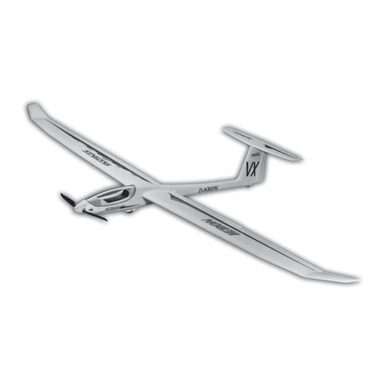
Erhältliche Varianten / Available versions / Version D disponible / Varianti disponibili / Variantes disponibles
# 21 4276
Heron
© Copyright by MULTIPLEX 2015
... 32 - 37
RR
# 26 4276
Heron
vorgesehen für den MULTIPLEX
Brushless-Antrieb
Designed for the MULTIPLEX
brushless power set
Ersatzteile
Replacement parts
Pièces de rechanges
Parti di ricambio
Repuestos
# 21 4276
Heron
# 33 2660 / 33 3660
# 33 2660 / 33 3660
2 ... 13
14 ... 25
26 ... 43
44 ... 54
55 ... 65
66 - 67
Version 1.0

Verwandte Anleitungen für Multiplex Heron 21 4276


Inhaltszusammenfassung für Multiplex Heron 21 4276
- Seite 1 Pièces de rechanges Illustrations Parti di ricambio Illnstrazioni Repuestos Iiustraciónes Erhältliche Varianten / Available versions / Version D disponible / Varianti disponibili / Variantes disponibles # 21 4276 # 26 4276 Heron Heron © Copyright by MULTIPLEX 2015 Version 1.0...
- Seite 2 WERDEN! ABNEHMBARE KLEINTEILE DES MODELLS KÖNNEN VON KINDERN UNTER 3 JAHREN VERSCHLUCKT WERDEN. ERSTICKUNGSGEFAHR! Beim Betrieb des Modells müssen alle Warnhinweise der BETRIEBSANLEITUNG beachtet werden. Die Multiplex Mo- dellsport GmbH & Co. KG ist nicht haftungspflichtig für Verluste und Beschädigungen jeder Art, die als Folge falschen Betriebes oder Missbrauches dieses Produktes, einschließlich der dazu benötigten Zubehörteile entstehen.
- Seite 3 Modell, des Akkus und des Ladegerätes beachten, Elektronik vor Wasser schützen. Auf ausreichende Kühlung bei Regler und Akku achten. Die Anleitungen unserer Produkte dürfen nicht ohne ausdrückliche Erlaubnis der Multiplex Modellsport GmbH & Co. KG (in schriftlicher Form) - auch nicht auszugsweise in Print- oder elektronischen Medien reproduziert...
- Seite 4 # 21 4276 Machen Sie sich mit dem Bausatz vertraut! MULTIPLEX - Modellbaukästen unterliegen während der Produktion einer ständigen Materialkontrolle. Wir hoffen, dass Sie mit dem Baukasteninhalt zufrieden sind. Wir bitten Sie jedoch, alle Teile (nach Stückliste) vor Verwendung zu prüfen, da bearbeitete Teile vom Umtausch ausgeschlossen sind.
- Seite 5 Wichtiger Hinweis Dieses Modell ist nicht aus Styropor ™! Daher sind Verklebungen mit Weißleim, Polyurethan oder Epoxy nicht möglich. Diese Kleber haften nur oberflächlich und platzen im Ernstfall einfach ab. Verwenden Sie nur Cyanacrylat-/Sekunden- kleber mittlerer Viskosität, vorzugsweise Zacki -ELAPOR® # 59 2727, der für ELAPOR® Partikelschaum optimierte und angepasste Sekundenkleber.
- Seite 6 4. Verschlussklammern und Motorspant einkleben Setzen Sie die Servos gemäß der Abbildung ein. Es reicht Kleben Sie die Verschlussklammern 22 rechts und links in aus, die Servos an den Laschen von Außen her mit Heiß- die Rumpfhälften. kleber zu sichern. So können diese im Reparaturfall einfach Den Motorspant 50 mit Zacki ELAPOR®...
- Seite 7 16. Seitenruder freischneiden Stecken Sie nun den vormontierten Propellermitnehmer wie Schneiden Sie mit einem scharfen Messer den Spalt un- abgebildet auf die Spannzange 79. Schieben Sie dann den terhalb des Seitenruders frei. Orientieren Sie sich beim gesamten Zusammenbau auf die Motorwelle und achten Freischneiden an der vorgegebenen Struktur.
- Seite 8 27. Querruder- / Wölbklappenservos (Flaps) einbauen mit ELAPOR® COLOR. Lackieren Sie, zum Beispiel, den Stellen Sie die Servos zunächst in die Neutrallage. Montie- Rahmen in Grau # 60 2711 und die Instrumentenbrett- ren Sie dann die Servohebel 2 Zähne nach vorne gedreht - Abdeckung in Schwarz # 60 2712.
- Seite 9 37. Dekor anbringen halten. Vorraussetzung dazu ist eine Fernsteuerung mit Dem Bausatz liegt ein Dekorbogen 2 bei. Die einzelnen entsprechenden Mischern. Schriftzüge und Embleme sind bereits ausgeschnitten und Lesen Sie hierzu die Anleitung Ihrer Fernsteuerung! werden nach unserer Vorlage (Baukastenbild) oder nach Die Butterflyeinstellung ermöglicht bei Bedarf steile und eigenen Vorstellungen aufgeklebt.
- Seite 10 Sie ein geflochtenes Seil mit ca. Ø 1 bis 1,5 mm, ca. 20 m in der Ebene direkt „über Kopf“ zu erkennen und auszu- fliegen, ist nur den geübtesten Piloten möglich. Fliegen lang. Am Ende wird eine Nylon-schlaufe befestigt (Ø 0,5 mm).
- Seite 11 Zeichen für wirkliches Können, der wirkliche Könner hat dies nicht nötig. Weisen Sie auch andere Piloten Wir, das MULTIPLEX -Team, wünschen Ihnen beim Bauen in unser aller Interesse auf diese Tatsache hin. Fliegen Sie und später beim Fliegen viel Freude und Erfolg.
- Seite 12 Stückliste KIT Heron # 21 4276 Lfd. Stück Bezeichnung Material Abmessungen Bauanleitung KIT Papier Reklamationsmeldung Modelle Papier Dekorbogen bedruckte Klebefolie 300 x 1000mm Rumpfhälfte links Elapor geschäumt Fertigteil Rumpfhälfte rechts mit Leitwerk Elapor geschäumt Fertigteil Kabinenrahmen Elapor geschäumt Fertigteil Höhenleitwerk Elapor geschäumt Fertigteil Tragfläche links mit Holm...
- Seite 13 Lfd. Stück Bezeichnung Material Abmessungen Holmrohre und Gurte Aussen-Holmrohr => im Flügel eingebaut! CFK-4-kt. 5,5 x 3,5 x 200 mm Aussen-Holmrohr => im Flügel eingebaut! ALU-4-kt. 10 x 8 x 900 mm Innen-Holmrohr => im Flügel eingebaut! CFK 4-kt. 8,8 x 6,9 x 1,5 x 900mm Rumpf-Verstärkungsrohr GFK-6-kt.
- Seite 32 Abb. 1 30.1 26.1 (4x) (2x) (2x) Abb. 2...
- Seite 33 Abb. 03 Abb. 04 Abb. 05 4x # 8 5031 => 300 mm Abb. 06 Abb. 07 2x # 8 5032 => 600 mm Abb. 08 Abb. 09...
- Seite 34 Nano-S # 6 5120 Abb. 10 Abb. 11 Abb. 12 Abb. 13 Ø1,3 x 215 mm (2x) Abb. 14 Abb. 15 Abb. 18 Abb. 16 Abb. 17...
- Seite 35 Abb. 19 Abb. 20 Abb. 21 Abb. 22 68 Ø1,3 x 400 mm (2x) Abb. 23 Abb. 24 Abb. 25 Abb. 26...
- Seite 36 # 8 5029 => 400 mm Nano-S # 6 5120 Abb. 27 Abb. 28 55 (2x) Abb. 29 Abb. 30 Querruder 30 (60 mm) 30.1 (70 mm) Aileron 26.1 26.1 Wölbklappe Flap Abb. 31b Abb. 31 61 + 62 Abb. 32 Abb.
- Seite 37 Abb. 35 Abb. 36 35 (2x) Abb. 37 Abb. 38 Motor Abb. 39 65 mm Abb. 40 Abb. 41...
- Seite 68 MULTIPLEX Modellsport GmbH & Co.KG Westliche Gewerbestrasse 1 D-75015 Bretten-Gölshausen www.multiplex-rc.de...