Balluff BNI PNT-508-055-P067 Betriebsanleitung
Vorschau ausblenden
Andere Handbücher für BNI PNT-508-055-P067:
- Montageanleitung (18 Seiten) ,
- Bedienungsanleitung (106 Seiten) ,
- Montageanleitung (28 Seiten)

Verwandte Anleitungen für Balluff BNI PNT-508-055-P067


Inhaltszusammenfassung für Balluff BNI PNT-508-055-P067
- Seite 1 BNI PNT-508-055-P067 BNI PNT-538-055-P067 deutsch Betriebsanleitung english User’s guide français Notice d’utilisation Manuale d’uso italiano Instrukcja obsługi polski...
- Seite 2 www.balluff.com...
- Seite 3 BNI PNT-508-055-P067 BNI PNT-538-055-P067 Betriebsanleitung deutsch...
- Seite 4 www.balluff.com...
-
Seite 5: Inhaltsverzeichnis
BNI PNT-508-055-P067 / BNI PNT-538-055-P067 Netzwerkschnittstelle Benutzerhinweise zu dieser Anleitung Gültigkeit Mitgeltende Dokumente Verwendete Symbole und Konventionen Bedeutung der Warnhinweise Verwendete Fachbegriffe und Abkürzungen Abbildungen Sicherheitshinweise Bestimmungsgemäße Verwendung Vernünftigerweise vorhersehbare Fehlanwendung Allgemeine Sicherheitshinweise Lieferumfang, Transport und Lagerung Lieferumfang Transport Lagerbedingungen... -
Seite 6: Netzwerkschnittstelle
BNI PNT-508-055-P067 / BNI PNT-538-055-P067 Netzwerkschnittstelle Technische Daten Umgebungsbedingungen Elektrische Merkmale Elektrischer Anschluss IO-Link PROFINET Material Mechanische Merkmale Zulassungen und Kennzeichnungen 8.8.1 CE 8.8.2 UL deutsch... -
Seite 7: Gültigkeit
Das allgemeine Warnsymbol in Verbindung mit dem Mitgeltende Dokumente Signalwort VORSICHT kennzeichnet eine Gefahr, die zu Weitere Informationen zu diesem Produkt finden Sie unter leichten oder mittelschweren Verletzungen führen www.balluff.com auf der Produktseite z. B. in folgenden kann. Dokumenten: GEFAHR –... -
Seite 8: Sicherheitshinweise
übertragenen Arbeiten beurteilen, mögliche Gefah- Die einwandfreie Funktion gemäß den Angaben in den ren erkennen und geeignete Sicherheitsmaßnahmen treffen technischen Daten wird nur mit geeignetem original Balluff kann. Zubehör zugesichert, die Verwendung anderer Komponen- Der Betreiber hat die Verantwortung, dass die örtlich ten bewirkt Haftungsausschluss. -
Seite 9: Lieferumfang, Transport Und Lagerung
BNI PNT-508-055-P067 / BNI PNT-538-055-P067 Netzwerkschnittstelle Lieferumfang, Transport und Lagerung Lieferumfang – IO-Link Gateway – 1 × Schraube M4x6 – Erdungsband aus Edelstahl – Montageanleitung Zubehör ist nicht im Lieferumfang enthalten und deshalb getrennt zu bestellen. Empfohlenes Zubehör finden Sie unter www.balluff.com auf der Produktseite. -
Seite 10: Produktbeschreibung
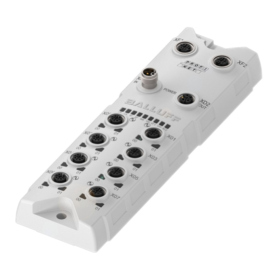
BNI PNT-508-055-P067 / BNI PNT-538-055-P067 Netzwerkschnittstelle Produktbeschreibung M12x1 (8x) M12x1 (male) M12x1 (3x) 8,50 1,80 M12x1 (8x) M12x1 (male) M12x1 (3x) 8,50 1,80 31,50 208,50 31,50 208,50 Bild 4-1: Abmessungen, Aufbau und Funktion Aufbau Funktion Der Profinet-IO-Link-Master ist ein dezentrales und konfi-... -
Seite 11: Produktbeschreibung
BNI PNT-508-055-P067 / BNI PNT-538-055-P067 Netzwerkschnittstelle Produktbeschreibung (Fortsetzung) Anzeigeelemente Status-LEDs Signal Bedeutung Grün Eingangsspannung OK Rot blinkend Eingangsspannung gering (< 18 V) Status-LEDs Grün Ausgangsspannung OK Rot blinkend Ausgangsspannung gering (< 18 V) Keine Ausgangsspannung vor- Port/Pin-LEDs: handen (< 11 V) Status der IO-Link- und I/O-Ports... -
Seite 12: Bedruckung
BNI PNT-508-055-P067 / BNI PNT-538-055-P067 Netzwerkschnittstelle Produktbeschreibung (Fortsetzung) Bedruckung Bestellcode Bild 4-4: Bedruckung (Beispiel) deutsch... -
Seite 13: Einbau Und Anschluss
BNI PNT-538-055-P067 dürfen Geräte ohne Tx− Transmit Data − galvanische Trennung wie z. B. Rx− Receive Data − BNI PNT-508-055-P067 nicht mit der gleichen Tab. 5-2: Pinbelegung PROFINET-Schnittstelle Stromquelle versorgt werden (siehe Tab. 5-1 und Tab. 5-3). – Die Gesamtstromstärke für die Sensor- und Aktorversorgung darf jeweils 16 A nicht über-... -
Seite 14: I/O-Port
BNI PNT-508-055-P067 / BNI PNT-538-055-P067 Netzwerkschnittstelle Einbau und Anschluss (Fortsetzung) 5.2.3 I/O-Port 5.2.4 Erdung Um EMV-Störungen entgegenzuwirken, muss der Funkti- onserdungsanschluss verwendet werden. ► Erdungsanschluss mit der Funktionserde (FE) der Maschine verbinden. Der FE-Anschluss zwischen Gehäuse und Maschine muss eine niedrige Impedanz aufwei-... -
Seite 15: Inbetriebnahme Und Betrieb
BNI PNT-508-055-P067 / BNI PNT-538-055-P067 Netzwerkschnittstelle Inbetriebnahme und Betrieb Inbetriebnahme Reinigung UL-Anforderungen siehe Kapitel 8.8.2 auf GEFAHR Seite 16. Unkontrollierte Systembewegungen Das Produkt darf nur in ausgeschaltetem Zustand gereinigt Bei der Inbetriebnahme und wenn das Netzwerk-Modul werden. Teil eines Regelsystems ist, dessen Parameter noch nicht... -
Seite 16: Reparatur, Demontage Und Entsorgung
BNI PNT-508-055-P067 / BNI PNT-538-055-P067 Netzwerkschnittstelle Reparatur, Demontage und Entsorgung Reparatur Reparaturen am Produkt dürfen nur von Balluff durchge- führt werden. Sollte das Produkt defekt sein, nehmen Sie Kontakt mit unserem Service-Center auf. Demontage ► Gerät nur in spannungsfreiem Zustand demontieren! Entsorgung ►... - Seite 17 BNI PNT-508-055-P067 / BNI PNT-538-055-P067 Netzwerkschnittstelle Technische Daten Die Angaben sind typische Werte bei 24 V DC und Raum- PROFINET temperatur. Das Produkt ist sofort betriebsbereit. PROFINET-Port 1 × 10Base-/100Base- Leistungsdaten für UL siehe Kapitel 8.8.2 auf Anschluss für PROFINET-Port M12, D-codiert, Buchse Seite 16.
-
Seite 18: Zulassungen Und Kennzeichnungen
BNI PNT-508-055-P067 / BNI PNT-538-055-P067 Netzwerkschnittstelle Technische Daten (Fortsetzung) Zulassungen und Kennzeichnungen Kabelgrößen Stromversorgungskabel: Nähere Informationen zu Richtlinien, Zulassungen Gelistetes oder R/C-Kabel (CYJV2/8) mit M12-Innenge- und Normen finden Sie unter www.balluff.com winde und L-codiertem Stecker mit mindestens 24 V, auf der Produktseite. - Seite 19 BNI PNT-508-055-P067 BNI PNT-538-055-P067 User’s Guide english...
- Seite 20 www.balluff.com...
- Seite 21 BNI PNT-508-055-P067 / BNI PNT-538-055-P067 Network interface User instructions for this guide Validity Other applicable documents Symbols and conventions Explanation of the warnings Technical terms and abbreviations used Pictures Safety notes Intended use Reasonably foreseeable misuse General safety notes Scope of delivery, transport and storage...
-
Seite 22: Network Interface
BNI PNT-508-055-P067 / BNI PNT-538-055-P067 Network interface Technical data Ambient conditions Electrical data Electrical connection IO-Link PROFINET Materials Mechanical features Approvals and designations 8.8.1 CE 8.8.2 UL english... -
Seite 23: User Instructions For This Guide
CAUTION indicates a hazard which can lead to Additional information about this product can be found at slight or moderate injuries. www.balluff.com on the product page, e.g. in the DANGER following documents: The general warning symbol in conjunction with the –... -
Seite 24: Safety Notes
Balluff accessories. Use of any other components appropriate safety measures. will void the warranty. -
Seite 25: Scope Of Delivery, Transport And Storage
BNI PNT-508-055-P067 / BNI PNT-538-055-P067 Network interface Scope of delivery, transport and storage Scope of delivery – IO-Link Gateway – 1 × Screw M4x6 – Stainless steel grounding strap – Installation guide Accessories are not included in the scope of delivery and must be ordered separately. -
Seite 26: Product Description
BNI PNT-508-055-P067 / BNI PNT-538-055-P067 Network interface Product description M12x1 (8x) M12x1 (male) M12x1 (3x) 8,50 1,80 M12x1 (8x) M12x1 (male) M12x1 (3x) 8,50 1,80 31,50 208,50 31,50 208,50 Fig. 4-1: Dimensions, design and function Construction Function The Profinet IO-Link master is a decentralized and... -
Seite 27: Display Elements
BNI PNT-508-055-P067 / BNI PNT-538-055-P067 Network interface Product description (continued) Display elements Status-LEDs Signal Meaning Green Input voltage OK Red flashing Input voltage low (< 18 V) Green Output voltage OK Status-LEDs Red flashing Output voltage low (< 18 V) No output voltage present (< 11 V) -
Seite 28: Labeling
BNI PNT-508-055-P067 / BNI PNT-538-055-P067 Network interface Product description (continued) Labeling Order code Type Fig. 4-4: Labeling (example) english... -
Seite 29: Installation And Connection
Signal Description BNI PNT-538-055-P067, devices without Transmit Data + galvanic isolation such as the Receive Data + BNI PNT-508-055-P067 must not be supplied with the same power source (see Tab. 5-1 and Tx− Transmit Data − Tab. 5-3). Rx− Receive Data −... -
Seite 30: I/O-Port
BNI PNT-508-055-P067 / BNI PNT-538-055-P067 Network interface Installation and connection (continued) 5.2.3 I/O-Port 5.2.4 Grounding To counteract EMC interference, the functional earth connection must be used. ► Connect the earth terminal to the functional earth (FE) of the machine. The FE connection between the housing and the machine must have a low impedance and Fig. -
Seite 31: Startup And Operation
BNI PNT-508-055-P067 / BNI PNT-538-055-P067 Network interface Startup and operation Startup Cleaning For UL requirements, see chapter 8.8.2 on DANGER page 16. Uncontrolled system movement The product may only be cleaned when switched off. When starting up, if the network module is part of a... -
Seite 32: Repair, Disassembly And Disposal
BNI PNT-508-055-P067 / BNI PNT-538-055-P067 Network interface Repair, disassembly and disposal Repair Repairs to the product may only be performed by Balluff. If the product is defective, contact our Service Center. Disassembly ► Only disassemble the device when it is de-energized! Disposal ►... -
Seite 33: Ambient Conditions
For performance data for UL, see chapter 8.8.2 on Connection for PROFINET-Port M12, D-coded, socket page 16. Cable types as per IEEE 802.3 Shielded twisted pair Further data can be found at www.balluff.com min. STP CAT 5/ on the product page. STP CAT 5e Data transmission rate 10/100 Mbit/s Ambient conditions Max. - Seite 34 Power supply cable: Additional information on directives, approvals and Listed or R/C cable (CYJV2/8) with M12 female thread and standards can be found at www.balluff.com on L-coded plug rated 24 V minimum, 16 A minimum for all the product page. models. S, SJ, SO, ST, SV, or R/C (AVLV2) listed cable marked or specified on the UL Style Page as suitable for external connections, rated 300 V minimum, 14 AWG...
- Seite 35 BNI PNT-508-055-P067 BNI PNT-538-055-P067 Notice d’utilisation français...
- Seite 36 www.balluff.com...
- Seite 37 BNI PNT-508-055-P067 / BNI PNT-538-055-P067 Interface réseau Guide d’utilisation de la présente notice Validité Autres documents de référence Symboles et conventions utilisés Signification des avertissements Termes techniques et abréviations utilisés Illustrations Consignes de sécurité Utilisation conforme aux prescriptions Mauvais usage raisonnablement prévisible Consignes générales de sécurité...
- Seite 38 BNI PNT-508-055-P067 / BNI PNT-538-055-P067 Interface réseau Caractéristiques techniques Conditions ambiantes Caractéristiques électriques Raccordement électrique IO-Link PROFINET Matériau Caractéristiques mécaniques Homologations et certifications 8.8.1 CE 8.8.2 UL français...
-
Seite 39: Autres Documents De Référence
BNI PNT-508-055-P067 / BNI PNT-538-055-P067 Interface réseau Guide d’utilisation de la présente notice Validité Signification des avertissements La présente notice fournit toutes les informations Respecter impérativement les avertissements de cette nécessaires pour une utilisation sûre des modules Profinet- notice et les mesures décrites pour éviter tout danger. -
Seite 40: Utilisation Conforme Aux Prescriptions
Balluff appropriés ; l’utilisation d’autres composants entraîne la Il est de la responsabilité de l’exploitant de veiller à ce nullité... -
Seite 41: Fourniture, Transport Et Stockage
BNI PNT-508-055-P067 / BNI PNT-538-055-P067 Interface réseau Fourniture, transport et stockage Fourniture – Passerelle IO-Link – 1 × vis M4x6 – Bande de mise à la terre en acier inoxydable – Notice de montage Les accessoires ne sont pas compris dans la fourniture et doivent être commandés séparément. -
Seite 42: Description Du Produit
BNI PNT-508-055-P067 / BNI PNT-538-055-P067 Interface réseau Description du produit M12x1 (8x) M12x1 (male) M12x1 (3x) 8,50 1,80 M12x1 (8x) M12x1 (male) M12x1 (3x) 8,50 1,80 31,50 208,50 31,50 208,50 Fig. 4-1 : Dimensions, structure et fonction Structure Fonction Le module Profinet-IO-Link Master est une passerelle... -
Seite 43: Éléments D'affichage
BNI PNT-508-055-P067 / BNI PNT-538-055-P067 Interface réseau Description du produit (suite) Éléments d’affichage LED d’état Signal Signification Vert Tension d’entrée OK Rouge Tension d’entrée faible (< 18 V) clignotant LED d’état Vert Tension de sortie OK Rouge Tension de sortie faible (< 18 V) -
Seite 44: Impression
BNI PNT-508-055-P067 / BNI PNT-538-055-P067 Interface réseau Description du produit (suite) Impression Symbolisation commerciale Type Fig. 4-4 : Impression (exemple) français... -
Seite 45: Montage Et Raccordement
BNI PNT-538-055-P067, les appareils sans séparation galvanique, tels que Broche Signal Description BNI PNT-508-055-P067, ne doivent pas être alimentés avec la même source d’alimentation Transmit Data + électrique (voir Tab. 5-1 et Tab. 5-3). Receive Data + – Le courant total pour l’alimentation des capteurs Tx−... -
Seite 46: Port I/O
BNI PNT-508-055-P067 / BNI PNT-538-055-P067 Interface réseau Montage et raccordement (suite) 5.2.3 Port I/O 5.2.4 Mise à la terre Pour contrer les interférences CEM, il convient d’utiliser la connexion de terre fonctionnelle. ► Relier la connexion de terre à la terre fonctionnelle (FE) de la machine. -
Seite 47: Mise En Service Et Fonctionnement
Pour plus d’informations, voir le certificat ECOLAB ► Les personnes doivent se tenir à l’écart de la zone sur la page produit du site www.balluff.com. de danger de l’installation. ► La mise en service ne doit être effectuée que par un ►... -
Seite 48: Réparation, Démontage Et Élimination Des Déchets
Si le produit est défectueux, veuillez contacter notre centre de service. Démontage ► Ne démonter l’appareil qu’à l’état hors tension ! Élimination des déchets ► Pour l’élimination des déchets, se conformer aux dispositions nationales. Vous trouverez des informations complémentaires sur la page produit du site www.balluff.com. français... -
Seite 49: Caractéristiques Techniques
M12, codage D, femelle chapitre 8.8.2, page 16. PROFINET Vous trouverez des informations supplémentaires Types de câble selon IEEE Blindé, paires torsadées sur la page produit du site www.balluff.com. 802.3 min. STP CAT 5/ STP CAT 5e Conditions ambiantes Vitesse de transmission 10/100 Mbit/s Longueur de câble max. -
Seite 50: Homologations Et Certifications
BNI PNT-508-055-P067 / BNI PNT-538-055-P067 Interface réseau Caractéristiques techniques (suite) Homologations et certifications Sections des câbles Câble d’alimentation électrique : Vous trouverez plus d’informations sur les Câble homologué ou R/C (CYJV2/8) avec connecteur mâle directives, les homologations et les normes sur la M12 à... - Seite 51 BNI PNT-508-055-P067 BNI PNT-538-055-P067 Manuale d’uso italiano...
- Seite 52 www.balluff.com...
- Seite 53 BNI PNT-508-055-P067 / BNI PNT-538-055-P067 Interfaccia di rete Avvertenze per l’utente riguardo alle presenti istruzioni Validità Documenti di riferimento Simboli e segni utilizzati Significato delle avvertenze Espressioni tecniche ed abbreviazioni utilizzate Immagini Avvertenze di sicurezza Utilizzo conforme Utilizzo improprio ragionevolmente prevedibile...
-
Seite 54: Interfaccia Di Rete
BNI PNT-508-055-P067 / BNI PNT-538-055-P067 Interfaccia di rete Dati tecnici Condizioni ambientali Caratteristiche elettriche Collegamento elettrico IO-Link PROFINET Materiale Caratteristiche meccaniche Autorizzazioni e contrassegni 8.8.1 CE 8.8.2 UL italiano... -
Seite 55: Avvertenze Per L'utente Riguardo Alle Presenti Istruzioni
BNI PNT-508-055-P067 / BNI PNT-538-055-P067 Interfaccia di rete Avvertenze per l’utente riguardo alle presenti istruzioni Validità Significato delle avvertenze Le presenti istruzioni forniscono tutte le informazioni Seguire scrupolosamente le avvertenze di sicurezza delle necessarie per un utilizzo sicuro dei seguenti Master presenti istruzioni e le misure descritte per evitare pericoli. -
Seite 56: Avvertenze Di Sicurezza
Balluff di tipo idoneo. L’utilizzo di altri componenti pericoli e di adottare misure di sicurezza adeguate. comporta la decadenza della garanzia. -
Seite 57: Fornitura, Trasporto E Magazzinaggio
BNI PNT-508-055-P067 / BNI PNT-538-055-P067 Interfaccia di rete Fornitura, trasporto e magazzinaggio Fornitura – Gateway IO-Link – 1× vite M4x6 – Nastro di terra in acciaio inox – Istruzioni di montaggio Gli accessori non sono compresi nella fornitura e quindi devono essere ordinati separatamente. -
Seite 58: Descrizione Del Prodotto
BNI PNT-508-055-P067 / BNI PNT-538-055-P067 Interfaccia di rete Descrizione del prodotto M12x1 (8x) M12x1 (male) M12x1 (3x) 8,50 1,80 M12x1 (8x) M12x1 (male) M12x1 (3x) 8,50 1,80 31,50 208,50 31,50 208,50 Fig. 4-1: Dimensioni, struttura e funzionamento Struttura Funzionamento Il Master IO-Link Profinet è un gateway decentralizzato e... -
Seite 59: Elementi Di Visualizzazione
BNI PNT-508-055-P067 / BNI PNT-538-055-P067 Interfaccia di rete Descrizione del prodotto (seguito) Elementi di visualizzazione LED di stato Segnale Significato Verde Tensione d’ingresso OK Rosso Tensione d’ingresso bassa lampeggiante (< 18 V) LED di stato Verde Tensione di uscita OK Rosso Tensione di uscita bassa (< 18 V) -
Seite 60: Stampigliatura
BNI PNT-508-055-P067 / BNI PNT-538-055-P067 Interfaccia di rete Descrizione del prodotto (seguito) Stampigliatura Codice d’ordine Tipo Fig. 4-4: Stampigliatura (esempio) italiano... -
Seite 61: Montaggio E Collegamento
BNI PNT-538-055-P067, non è consentito alimentare dalla stessa fonte di corrente i Segnale Descrizione dispositivi senza separazione galvanica, come ad es. BNI PNT-508-055-P067 (vedere Tab. 5-1 Transmit Data + e Tab. 5-3). Receive Data + – L’intensità di corrente totale per l’alimentazione Tx−... -
Seite 62: Porta I/O
BNI PNT-508-055-P067 / BNI PNT-538-055-P067 Interfaccia di rete Montaggio e collegamento (seguito) 5.2.3 Porta I/O 5.2.4 Messa a terra Al fine di contrastare disturbi elettromagnetici, andrà utilizzato il collegamento di messa a terra funzionale. ► Allacciare il collegamento di messa a terra alla messa a terra funzionale (FE) della macchina. -
Seite 63: Messa In Funzione E Funzionamento
BNI PNT-508-055-P067 / BNI PNT-538-055-P067 Interfaccia di rete Messa in funzione e funzionamento Messa in funzione Pulizia Requisiti UL: vedere capitolo 8.8.2 a pagina 16. PERICOLO Movimenti incontrollati del sistema Il prodotto può essere pulito solo quando è spento. Durante la messa in funzione e se il modulo di rete fa Il prodotto è... -
Seite 64: Riparazione, Smontaggio E Smaltimento
BNI PNT-508-055-P067 / BNI PNT-538-055-P067 Interfaccia di rete Riparazione, smontaggio e smaltimento Riparazione Gli interventi di riparazione sul prodotto andranno effettuati esclusivamente da Balluff. Qualora il prodotto dovesse presentare difetti, contattare il nostro Service Center. Smontaggio ► Smontare l’apparecchio esclusivamente se... - Seite 65 BNI PNT-508-055-P067 / BNI PNT-538-055-P067 Interfaccia di rete Dati tecnici I dati sono valori tipici a 24 V DC e a temperatura PROFINET ambiente. Il prodotto è immediatamente pronto al funzionamento. Porta Profinet 1× 10Base-/100Base-Tx Collegamento per porta Profinet M12, con codifica D, Dati prestazionali per UL: vedere capitolo 8.8.2 a...
-
Seite 66: Autorizzazioni E Contrassegni
BNI PNT-508-055-P067 / BNI PNT-538-055-P067 Interfaccia di rete Dati tecnici (Continua) Autorizzazioni e contrassegni Dimensioni dei cavi Cavo di alimentazione di corrente: Ulteriori informazioni su direttive, omologazioni e Cavo elencato o cavo R/C (CYJV2/8) con filettatura interna norme sono disponibili all’indirizzo M12 e connettore con codifica L di minimo 24 V, almeno... - Seite 67 BNI PNT-508-055-P067 BNI PNT-538-055-P067 Instrukcja obsługi polski...
- Seite 68 www.balluff.com...
- Seite 69 BNI PNT-508-055-P067 / BNI PNT-538-055-P067 Złącze sieciowe Wskazówki dla użytkownika do tej instrukcji Zakres obowiązywania Dodatkowo obowiązujące dokumenty Zastosowane symbole i konwencje Znaczenie ostrzeżeń Zastosowane pojęcia i skróty Ilustracje Zasady bezpieczeństwa Użytkowanie zgodne z przeznaczeniem Przewidywalne nieprawidłowe użytkowanie Ogólne zasady bezpieczeństwa...
- Seite 70 BNI PNT-508-055-P067 / BNI PNT-538-055-P067 Złącze sieciowe Dane techniczne Warunki otoczenia Właściwości elektryczne Podłączenie elektryczne IO-Link PROFINET antypoślizgowy Właściwości mechaniczne Certyfikaty i oznaczenia 8.8.1 CE 8.8.2 UL polski...
-
Seite 71: Wskazówki Dla Użytkownika Do Tej Instrukcji
BNI PNT-508-055-P067 / BNI PNT-538-055-P067 Złącze sieciowe Wskazówki dla użytkownika do tej instrukcji Zakres obowiązywania Znaczenie ostrzeżeń Niniejsza instrukcja zawiera wszystkie potrzebne W celu uniknięcia niebezpieczeństw koniecznie informacje dotyczące bezpiecznego użytkowania przestrzegać ostrzeżeń i czynności opisanych w niniejszej poniższych urządzeń Profinet-IO-Link-Master: instrukcji. -
Seite 72: Zasady Bezpieczeństwa
BNI PNT-508-055-P067 / BNI PNT-538-055-P067 Złącze sieciowe Zasady bezpieczeństwa Użytkowanie zgodne z przeznaczeniem Ogólne zasady bezpieczeństwa Profinet-IO-Link-Master służy jako wydzielony moduł WE/ WY i IO-Link do podłączania do magistrali polowej Czynności takie jak montaż, podłączenie oraz PROFINET i jest przeznaczony do zastosowania w uruchomienie mogą... -
Seite 73: Zakres Dostawy, Transport I Przechowywanie
BNI PNT-508-055-P067 / BNI PNT-538-055-P067 Złącze sieciowe Zakres dostawy, transport i przechowywanie Zakres dostawy – Bramka IO-Link – 1 śruba M4x6 – Taśma uziemiająca ze stali szlachetnej – Instrukcja montażu Wyposażenie nie jest zawarte w zakresie dostawy i dlatego należy je zamawiać osobno. -
Seite 74: Opis Produktu
BNI PNT-508-055-P067 / BNI PNT-538-055-P067 Złącze sieciowe Opis produktu M12x1 (8x) M12x1 (male) M12x1 (3x) 8,50 1,80 M12x1 (8x) M12x1 (male) M12x1 (3x) 8,50 1,80 31,50 208,50 31,50 208,50 Rys. 4-1: Wymiary, budowa i działanie Budowa Działanie Profinet-IO-Link-Master jest zdecentralizowaną i Przyłącze FE... -
Seite 75: Elementy Wskazujące
BNI PNT-508-055-P067 / BNI PNT-538-055-P067 Złącze sieciowe Opis produktu (ciąg dalszy) Elementy wskazujące Diody LED statusu Sygnał Znaczenie zielony napięcie wejściowe OK czerwony niskie napięcie wejściowe (< 18 V) migający Diody LED statusu zielony napięcie wyjściowe OK czerwony niskie napięcie wyjściowe (< 18 V) migający... -
Seite 76: Nadruk
BNI PNT-508-055-P067 / BNI PNT-538-055-P067 Złącze sieciowe Opis produktu (ciąg dalszy) Nadruk Kod zamówieniowy Rys. 4-4: Nadruk (przykład) polski... -
Seite 77: Montaż I Podłączenie
BNI PNT-508-055-P067 / BNI PNT-538-055-P067 Złącze sieciowe Montaż i podłączenie Montaż Wtyk M12 (kodowanie L) Gniazdo M12 (kodowanie Wymiary patrz Rys. 4-1 na stronie 8. ► Zamocować moduł 2 śrubami M6 z maksymalnym momentem obrotowym 3 Nm z wykorzystaniem otworów mocujących (patrz Rys. 4-2na stronie 8). -
Seite 78: Port We/Wy
BNI PNT-508-055-P067 / BNI PNT-538-055-P067 Złącze sieciowe Montaż i podłączenie (cd.) 5.2.3 Port we/wy 5.2.4 Uziemienie Aby zapobiegać zakłóceniom EMC, należy użyć funkcyjnego przyłącza uziemienia. ► Przyłącze uziemienia należy podłączyć z uziemieniem funkcyjnym (FE) maszyny. Przyłącze FE między obudową a maszyną musi mieć... -
Seite 79: Uruchomienie I Eksploatacja
BNI PNT-508-055-P067 / BNI PNT-538-055-P067 Złącze sieciowe Uruchomienie i eksploatacja Uruchomienie Czyszczenie Wymagania UL patrz rozdział 1.1.2 na NIEBEZPIECZEŃSTWO stronie 16. Niekontrolowany ruch systemu Produkt może być czyszczony tylko w stanie wyłączonym. Przy uruchamianiu oraz jeśli moduł sieciowy jest częścią Produkt może być czyszczony metodą zmywania i jest systemu regulacyjnego, którego parametry nie są... -
Seite 80: Naprawa, Demontaż I Utylizacja
BNI PNT-508-055-P067 / BNI PNT-538-055-P067 Złącze sieciowe Naprawa, demontaż i utylizacja Naprawa Naprawy produktu mogą być przeprowadzane wyłącznie przez firmę Balluff. Gdyby produkt był uszkodzony, prosimy skontaktować się z naszym centrum serwisowym. Demontaż ► Demontować urządzenie wyłącznie po odłączeniu od napięcia! -
Seite 81: Warunki Otoczenia
BNI PNT-508-055-P067 / BNI PNT-538-055-P067 Złącze sieciowe Dane techniczne Dane dotyczą typowych wartości przy 24 V DC i PROFINET temperaturze pokojowej. Produkt jest gotowy do użycia natychmiast. Port PROFINET 1 × 10Base-/ 100Base-Tx Parametry dla UL patrz rozdział 1.1.2 na Przyłącze do portu PROFINET M12, kodowanie D, stronie 16. - Seite 82 BNI PNT-508-055-P067 / BNI PNT-538-055-P067 Złącze sieciowe Dane techniczne (cd.) Certyfikaty i oznaczenia Rozmiary kabli Kabel zasilający: Bliższe informacje dotyczące dyrektyw, Wymieniony kabel lub kabel R/C (CYJV2 / 8) z gwintem dopuszczeń i norm znajdziesz na wewnętrznym M12 i wtyczką z kodowaniem L o napięciu www.balluff.com na stronie produktu.
- Seite 84 Americas Service Center Asia Pacific Service Center Poland Greater China Balluff Sp. z o.o. Balluff Inc. Balluff Automation (Shanghai) Co., Ltd. Ul. Graniczna 21A 8125 Holton Drive No. 800 Chengshan Rd, 8F, Building A, 54-516 Wrocław Florence, KY 41042 Yunding International Commercial Plaza...