Balluff BNI EIP-502-105-R015 Betriebsanleitung
Ethernet/ip ip67 module

Verwandte Anleitungen für Balluff BNI EIP-502-105-R015


Inhaltszusammenfassung für Balluff BNI EIP-502-105-R015
- Seite 1 BNI EIP-502-105-R015 BNI EIP-508-105-R015 EtherNet/IP™ IP67 modules deutsch Betriebsanleitung english User’ s guide 中文 用户指南 한국어 사용자 가이드 日本語 ユーザーガイド...
- Seite 2 www.balluff.com...
- Seite 3 BNI EIP-502-105-R015 BNI EIP-508-105-R015 EtherNet/IP™ IP67-Module Bedienungsanleitung...
-
Seite 4: Inhaltsverzeichnis
5.1. Integration in Rockwell RS Logix 5000 5.2. Adressvorgaben 5.3. Datenkonfiguration 5.4. Konfigurationsdaten Modulkonfiguration BNI EIP-502-105-XXXX Modulkonfiguration BNI EIP-508-105-XXXX Modulkonfiguration BNI EIP-507-005-Z040, BNI EIP-527-005-Z040 Modulkonfiguration BNI EIP-508-XXX-XXXX-C06 IO-Link Port-Konfiguration Zyklus Einstellungen Validierungseinstellungen Parameter Server Uploadflag am IO-Link-Device Konfiguration über Explicit Messages www.balluff.com... - Seite 5 Balluff Netzwerkschnittstelle EtherNet/IP™ Quickconnect RockwellAutomation Produkte, welche mit QuickConnect kompatibel sind Beispiel mit Rockwell Komponenten PLC Programm Fault State Fault State aktivieren / deaktivieren Fault State Action IO-Link Device Parametrierung Read IO-Link Parameter Write IO-Link Parameter Prozessdaten 7.1. Prozessdateneingaben Standard-Eingabedaten IO-Link Eingabedaten 7.2.
-
Seite 6: Hinweise
Querverweise zeigen an, wo sich weitere Informationen zu dem Thema befinden. Querverweise 1.3. Symbole Hinweis Dieses Symbol kennzeichnet allgemeine Hinweise. Achtung! Dieses Symbol kennzeichnet einen Sicherheitshinweis, der unbedingt beachtet werden muss. Balluff Netzwerkschnittstelle 1.4. Abkürzungen Standard-Eingangsport EtherNet/IP™ Elektromagnetische Verträglichkeit Funktionserde Standard-Ausgangsport Produktansichten und Bilder können in dieser Bedienungsanleitung vom angegebenen 1.5. -
Seite 7: Sicherheit
Spannung Vor dem Arbeiten an dem Gerät dessen Stromversorgung abschalten. Hinweis Im Interesse einer ständigen Verbesserung des Produkts behält sich die Balluff GmbH vor, die technischen Daten des Produkts und den Inhalt dieser Anleitung jederzeit, ohne Ankündigung zu ändern. www.balluff.com... -
Seite 8: Erste Schritte
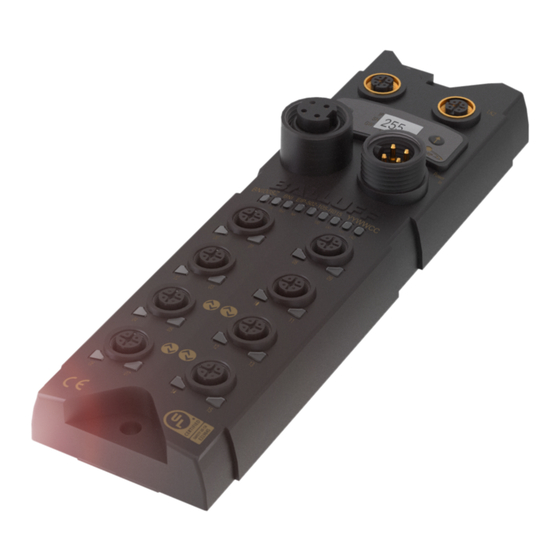
Port 02 / 03 (IO-Link, Standard I/O) Status-LED: Kommunikation/Modul Port 00 / 01 (IO-Link, Standard I/O) Port 08 / 09 (IO-Link, Standard I/O) Stromversorgung Ausgang Pin/Port-LED : Signalstatus EtherNet/IP™-Port 1 Port 10 / 11 (IO-Link, Standard I/O) Erdungsanschluss Port 12 / 13 (IO-Link, Standard I/O) www.balluff.com... -
Seite 9: Mechanischer Anschluss
Balluff Netzwerkschnittstelle EtherNet/IP™ Erste Schritte Das Modul wird mittels 2 M6-Schrauben und 2 Unterlegscheiben befestigt. 3.2. Mechanischer Eine Isolierauflage ist getrennt erhältlich. Anschluss 3.3. Elektrischer Anschluss Netzanschluss Funktion Beschreibung +24 V Aktorversorgung +24 V Modul- / Sensorversorgung 7/8”, male GND Modul- / Sensor- und Aktorversorgung 7/8”... -
Seite 10: I/O-Port
Funktion +24 V, 1,6 A Eingang/Ausgang 2 A IO-Link/Eingang/Ausgang 2 A n.a. Port Port 00/01, 02/03, 08/09, 10/11 04/05, 06/07, 12/13, 14/15 BNI EIP-502-105-R015 IN / OUT IN / OUT / IO-Link BNI EIP-508-105-R015 IN / OUT / IO-Link www.balluff.com... -
Seite 11: Technische Daten
Balluff Netzwerkschnittstelle EtherNet/IP™ Technische Daten 4.1. Abmessungen 4.2. Mechanische Kunststoffgehäuse resistent (Fortron 6165 A6 Gehäusewerkstoff schwarz) Daten Gehäuseschutzart gemäß IEC 60529 IP 67 (nur wenn eingesteckt oder eingedreht) Versorgungsspannung 7/8" 4-polig, Stecker / Buchse Eingangsports / Ausgangsports M12, A-codiert (8x Buchse) Ausmaße (B x H x T in mm) -
Seite 12: Ethernet
Fester Bustakt nicht möglich rot-grün blinkend Anfangssequenz Modul hat keine IP-Adresse grün blinkend Module hat IP, aber keine Verbindung hergestellt grün Verbindung hergestellt Netz rot blinkend Verbindungstimeout rot-grün blinkend Anfangssequenz Bustakt: 10 Mbit/s gelb Bustakt: 100 Mbit/s grün Datentransfer www.balluff.com... -
Seite 13: Port
Balluff Netzwerkschnittstelle EtherNet/IP™ Technische Daten Jeder Port verfügt über zwei zweifarbige LEDs zur Anzeige der I/O-Zustände. Port Display Status Beschreibung I/O-Status Der Status der Eingangs- oder Ausgangs-Pins ist 0 gelb I/O-Status Der Status der Ein- oder Ausgangs-Pins ist 1 rot blinkend... -
Seite 14: Integration
Integration Hier sehen Sie ein Beispiel, wie das Modul in einen Rockwell RS Logix 5000 integriert 5.1. Integration in werden kann: Rockwell RS Logix 5000 Zuerst offline gehen Rechter Mausklick auf Ethernet (auf der korrekten Scannercard) neues Modul wählen www.balluff.com... - Seite 15 Balluff Netzwerkschnittstelle EtherNet/IP™ Integration Anschließend wählen Sie als ETHERNET-Modul im Kommunikationspfad das allgemeine Ethernetmodul Zur Auswahl des allgemeinen Formats Data-SINT, zum Eingeben der IP-Adresse des Moduls und zur Eingabe der korrekten Verbindungsparameter, ist nun ein benutzer- definierter Tag-Name einzutippen. www.balluff.com...
- Seite 16 Integration Das neue Modul und die entsprechenden Controller-Tags werden automatisch erzeugt. Anschließend laden Sie die Konfiguration herunter www.balluff.com...
- Seite 17 Balluff Netzwerkschnittstelle EtherNet/IP™ Integration Nach Abschluss des Downloads können Sie die Tags über die Option Controller-Tags beobachten und ansteuern. Stellen Sie sicher, dass Sie den korrekten Tag-Namen auswählen, den Sie vorab konfiguriert haben. Die Eingabe-, Ausgabe- und Konfigurationsdaten hierzu sind auf den nachfolgenden Seiten beschrieben.
-
Seite 18: Adressvorgaben
Konfiguration des IO-Link Port 5 146…1 IO-Link Port 6 Konfiguration des IO-Link Port 6 170…1 IO-Link Port 7 Konfiguration des IO-Link Port 7 Hinweis Der BNI EIP-508-XXX-XXXX-C06 verfügt über keine Konfigurationsdaten. Diese sind fest definiert und können nicht verändert werden. www.balluff.com... -
Seite 19: Modulkonfiguration
Balluff Netzwerkschnittstelle EtherNet/IP™ Integration Modul- Beschreibung konfiguration BNI EIP-502-105-XXXX Port-Funktion 0x00: Standard-I/O 0x01: IO-Link Modul- konfiguration BNI Beschreibung EIP-508-105-XXXX Port-Funktion 0x00: Standard-I/O 0x01: IO-Link Modul- konfiguration Beschreibung BNI EIP-507-005- Z040, BNI EIP- Port-Funktion 527-005-Z040 0x00: Standard-I/O Reserviert 0x01: IO-Link Die IO-Link Ports sind immer aktiviert. -
Seite 20: Io-Link Port-Konfiguration
Seriennummer Seriennummer 16 Parameter-Server 0x8X Einschalten 0x0X Ausschalten Parameter-Server 0x40 Löschen 0xX1 Upload einschalten 0xX2 Download einschalten Die Daten der anderen IO-Link Ports sind identisch aufgebaut und im Folgenden beschrieben. … Beim BNI EIP-508-XXX-XXXX-C06 sind die Daten nicht einstellbar. www.balluff.com... -
Seite 21: Zyklus Einstellungen
Balluff Netzwerkschnittstelle EtherNet/IP™ Integration Mit diesem Parameter kann die IO-Link Kommunikationsgeschwindigkeit beeinflusst Zyklus werden. Berechnet durch den Multiplikator und der Zeit Basis kann die IO-Link Zykluszeit Einstellungen erhöht werden. Die Zeit Basis ist in Tabelle B3 beschrieben, der Multiplikator wird von 0…63 dezimal eingegeben. -
Seite 22: Parameter Server
IO-Link-Device Um das Uploadflag eines IO-Link-Geräts zu aktivieren, muss im Index 0x02, Subindex 0, der Datenwert 0x05 eingegeben werden. (Informationen zur Parametrierung über IO-Link siehe Kapitel „Webserver“ unter „Geräteeigenschaften“ oder Kapitel „Konfiguration über Explicit Messages“ unter „IO-Link Device Parametrierung) www.balluff.com... - Seite 23 Balluff Netzwerkschnittstelle EtherNet/IP™ Konfiguration über Explicit Messages Die Module BNI EIP-50x-105-X015 können über die QuickConnect Funktion Quickconnect schneller hochgefahren und eingebunden werden. Durch das aktivieren von QuickConnect werden alle notwendigen Porteigenschaften am Modul automatisch übernommen: • Statische IP Adresse •...
-
Seite 24: Konfiguration Über Explicit Messages
Konfiguration über Explicit Messages Rockwell- Automation Produkte, welche mit QuickConnect kompatibel sind Quelle: Allen-Bradley Ethernet/IP QuickConnect Application Technique Seite 13 www.balluff.com... -
Seite 25: Beispiel Mit Rockwell Komponenten
Balluff Netzwerkschnittstelle EtherNet/IP™ Konfiguration über Explicit Messages Beispiel mit Rockwell Komponenten Quelle: Allen-Bradley Ethernet/IP QuickConnect Application Technique Seite 12 Folgendes ist noch zu beachten: • Verbindung PLC direkt zu Quickconnect Slave mit Crossover Kabel • Verbindung Slave zu Slave mit Patch Kabel •... -
Seite 26: Plc Programm
Konfiguration über Explicit Messages PLC Programm Quelle: Allen-Bradley Ethernet/IP QuickConnect Application Technique Seite 29 www.balluff.com... - Seite 27 Balluff Netzwerkschnittstelle EtherNet/IP™ Konfiguration über Explicit Messages Quelle: Allen-Bradley Ethernet/IP QuickConnect Application Technique Seite 30 www.balluff.com...
- Seite 28 Konfiguration über Explicit Messages Quelle: Allen-Bradley Ethernet/IP QuickConnect Appliation Technique Seite 31 www.balluff.com...
-
Seite 29: Fault State
Balluff Netzwerkschnittstelle EtherNet/IP™ Konfiguration über Explicit Messages Quelle: Allen-Bradley Ethernet/IP QuickConnect Appliation Technique Seite 32 Fault State Für jeden Ausgang an den Port Pins kann ein sicherer Zustand vordefiniert werden, die dieser im Falle eines Verlustes der Buskommunikation einnehmen soll. -
Seite 30: Io-Link Device Parametrierung
Anzahl der Ports Source Length muss mindestens den gelesenen Parametern entsprechen, kann aber auch größer eingegeben werden. (In diesem Beispiel 100 Bytes) Als Source Element (Write) und als Destination Element (Read), jeweils ein SINT[100] Array anlegen und die erste Zeile[0] auswählen. www.balluff.com... - Seite 31 Balluff Netzwerkschnittstelle EtherNet/IP™ Konfiguration über Explicit Messages Im Source Element Array (Write) wird eingegeben, welcher Index gelesen werden soll. In diesem Beispiel ist das der Index 0x4E. Im Destination Array (Read) wird der ausgelesene Wert angezeigt. Im Falle eines Parametrierfehlers wird der Fehlercode dort ebenfalls angezeigt.
-
Seite 32: Write Io-Link Parameter
Fehlercode angezeigt. Im Fenster "Communication" muss ebenfalls das Ethernet Modul ausgewählt werden, auf welchem parametriert werden soll. Hinweis Die Explicit Messages Funktionen sind laut der Volume 1: Common Industrial Protocol Specification und der Volume 2: Ethernet/IP Adaption of CIP implementiert. www.balluff.com... -
Seite 33: Prozessdaten
Balluff Netzwerkschnittstelle EtherNet/IP™ Prozessdaten Die Eingabedaten haben einen Umfang von 200 Bytes. Werfen Sie einen Blick auf unten 7.1. Prozessdaten- stehende Tabellen für die Zuordnung der Prozessdateneingaben. eingaben BNI EIP-502-105-R015 Byte Modulteil Beschreibung 0…7 Standard I/O-Ports Prozessdateneingaben an den Standardeingängen 8…55... -
Seite 34: Io-Link Eingabedaten
Event code hoch Event 2 Type: Event code niedrig 0: Reserviert Mode Type 1: Meldung Event code hoch Event 3 2: Warnung Event code niedrig 3: Fehler … Die Daten der anderen IO-Link Ports sind identisch aufgebaut und im Folgenden beschrieben www.balluff.com... -
Seite 35: Prozessdatenausgaben
Balluff Netzwerkschnittstelle EtherNet/IP™ Prozessdaten Die Ausgabedaten haben einen Umfang von 134 Bytes. Werfen Sie einen Blick auf unten 7.2. Prozessdaten- stehende Tabellen für die Zuordnung der Prozessdatenausgaben. ausgaben BNI EIP-502-105-R015 Byte Modul part Beschreibung 0…5 Standard I/O-Ports Prozessdatenausgaben an den Standardeingängen 6…37... -
Seite 36: Display
2 Pfeil-Taste 5 „Set“-Taste 3 Oktett-Cursor 6 LED 8.4. Display- Cursor zur Auswahl des Adresstyps informationen Cursor zur Auswahl des Oktetts IP: IP-Adresse 3: erstes Oktett SN: Subnetzadresse 2: zweites Oktett GW: Gateway-Adresse 1: drittes Oktett 0: viertes Oktett www.balluff.com... -
Seite 37: Design Und Symbole
Balluff Netzwerkschnittstelle EtherNet/IP™ Display In den folgenden Flussdiagrammen werden einige Symbole zur Beschreibung der Display- 8.5. Design und Funktionalität verwendet: Symbole Aktueller Zustand Umschalten Bedingung: Kurzes Drücken der Set-Taste Bedingung: Langes Drücken der Set-Taste (min. 3 Sekunden) Bedingung: Kurzes Drücken der Pfeiltaste 8.6. -
Seite 38: Ip-Setup
Die vollständig eingegebene Adresse wird durch kurzes Drücken der Set-Taste bei Bearbeitung des ersten Oktetts gespeichert. Der eingegebene Wert erscheint unmittelbar im Anschluss auf der IP-Übersichtsanzeige. • Manuelle Veränderungen von IP, Subnet oder Gateway führen zu einer automatischen Änderung des IP-Setups zu “statisch”. www.balluff.com... - Seite 39 Balluff Netzwerkschnittstelle EtherNet/IP™ Display 8.10. Editiermodus • Im Menü Netzwerkkonfig IP-/Subnetz- oder Gatewayadresse auswählen. • Die Set-Taste lange drücken, um in den Editiermodus zu wechseln. • Die Pfeil-Taste kurz drücken, um die Nummer zu ändern. • Die Set-Taste kurz drücken um zur nächsten Stelle zu gelangen •...
-
Seite 40: Modulinformationen
Die Funktion plc-lock kann ebenfalls durch das Einstellen eines Bits in den Prozessdatenausgaben genutzt werden. (siehe Bitlayout, Standard-Ausgabedaten) Hinweis Der Bearbeitungsmodus kann im Display nicht ausgewählt werden, wenn in den Prozessdateneingaben der plc lock durch ein Bit eingestellt ist (siehe Bit- Layout, Standard-Ausgabedaten) www.balluff.com... -
Seite 41: Webserver
Balluff Netzwerkschnittstelle EtherNet/IP™ Webserver Das BNI Feldbusmodul enthält einen integrierten Webserver zum Abruf detaillierter 9.1. Allgemeines Geräteinformationen und zur Konfiguration des Geräts. Zur Nutzung dieses Webinterfaces müssen Sie zuerst sicherstellen, dass die Integration des Moduls in ihr Netzwerk korrekt erfolgt ist. Dazu muss das IP-Subnetz des BNI-Moduls von dem PC aus erreichbar sein, auf dem der Browser betreiben wird. -
Seite 42: Navigation / Info
Im oberen Fensterbereich befindet sich die Navigationszeile, die einen Wechsel zwischen 9.2. Navigation / Info den verschiedenen Dialogen des Webinterfaces ermöglicht. Klicken Sie dazu auf das entsprechende Symbol. Bei Auswahl des Reiters „Info“ erscheint folgende Übersicht: Das BALLUFF-Logo oben links verlinkt zur internationalen Balluff Homepage. www.balluff.com... -
Seite 43: Login / Logout
Balluff Netzwerkschnittstelle EtherNet/IP™ Webserver Um über das Webinterface auf dem Feldbusmodul Konfigurationseinstellungen vornehmen 9.3. Login / Logout zu können, muss zuvor ein Login erfolgen. Funktionalitäten, die ohne Login nicht genutzt werden können, sind durch ausgegraute Buttons erkennbar. Das Standardpasswort lautet: BNI PNT-XXX-XXX-XXXX „BNIPNT“... -
Seite 44: Dialog "Home
Status des Moduls dargestellt. Nach Auswahl von „LED Legend“ erscheint ein Hilfe- Dialog, der die Bedeutung der LEDs erläutert. Ist ein IO-Link-Gerät an einem der konfigurierten IO-Link-Ports angeschlossen, werden neben den Moduldaten auch einige Gerätedaten als Link angezeigt. Nach Anwählen einer dieser Links wird der entsprechende Gerätedialog aufgerufen. www.balluff.com... - Seite 45 Balluff Netzwerkschnittstelle EtherNet/IP™ Webserver PNT: EIP: www.balluff.com...
-
Seite 46: Dialog "Ports
Konventionen). Unter dem Punkt „Events“ können Sie sehen, ob ein Diagnoseereignis vom IO-Link-Gerät vorliegt. Unter dem Punkt „Parameter Server Content“ können Sie den Inhalt des Parameter-Servers einsehen, wenn Parameterdaten auf dem Parameter-Server gespeichert sind. Dialog „Ports“ mit direktem Parameterzugriff www.balluff.com... -
Seite 47: Passende Iodd Hochgeladen
Balluff Netzwerkschnittstelle EtherNet/IP™ Webserver Ist passend zu dem IO-Link-Gerät, das am aktuell selektierten Port angeschlossen ist, eine Passende IODD IODD hochgeladen worden (siehe “Dialog „IODD“, wird nicht der normale Dialog für „Process hochgeladen Data“ und „Parameters“ angezeigt, sondern ein erweiterter Dialog. - Seite 48 Hat die IODD des IO-Link-Geräts am aktuell ausgewählten Port auch Parameter, werden diese als Tabelle angezeigt (siehe folgender Screenshot). In diesem Beispiel werden die Parameter der Balluff Smart Light angezeigt. Die Smart Light ist eine Meldeleuchte, die in drei Modi betrieben werden kann. Diese Modi können über einen IO-Link Parameter eingestellt werden.
-
Seite 49: Dialog „Iodd
Balluff Netzwerkschnittstelle EtherNet/IP™ Webserver Über diesen Dialog können IODDs (Gerätebeschreibungsdateien für IO-Link-Geräte) und die 9.6. Dialog „IODD“ zugehörigen Gerätebilder auf das Feldbusmodul hochgeladen werden, damit im Dialog „Ports“ eine detailliertere Darstellung der angeschlossenen IO-Link-Geräte möglich ist. Bei angeschlossenen IO-Link-Geräten und aktivierten IO-Link-Ports zeigt der Dialog eine Tabelle mit Informationen über die IO-Link-Geräte an. -
Seite 50: Dialog „Config
Die Konfigurationsseite ermöglicht nach dem Einloggen die Konfiguration des Moduls. Sie 9.7. Dialog „Config“ können sowohl die Modul-Informationstexte als auch die Portkonfiguration ändern. Die Aktion „Set Ports“ wird nicht dauerhaft im Gerät gespeichert und geht mit dem nächsten Reboot oder Reset verloren. PNT / ECT: www.balluff.com... - Seite 51 Balluff Netzwerkschnittstelle EtherNet/IP™ Webserver EIP: Der Parametersatz „Module Configuration“ auf der linken Seite wird durch Drücken des Buttons „Save Configuration“ angewendet und dauerhaft im Gerät hinterlegt. Der Button „Reboot“ startet das Gerät neu, als wenn die Versorgungsspannung des Moduls ab- und wieder angeschaltet worden wäre.
-
Seite 52: Dialog "Log
Wenn Sie eine detaillierte Frage zu einem konkreten Fall haben, senden Sie uns einen Screenshot dieser Website oder drucken Sie die Website als PDF. Das Logging stellt aufgetretene Ereignisse in ihrer zeitlichen Abhängigkeit dar. Damit ist es ein Werkzeug zur detaillierten Störungssuche in Anlagen. www.balluff.com... - Seite 53 Balluff Netzwerkschnittstelle EtherNet/IP™ Webserver Die Klassifizierung der Ereignisse erfolgt über die Spalte „Severity“: Interner Fehler (Emergency, Alert, Critical) → Das Feldbusmodul hat einen Defekt an sich selbst (Hardware oder Software) festgestellt, was im Normalbetrieb nicht vorkommen darf. Falls dieser Fall doch eintritt, muss das Modul gewartet oder ausgetauscht werden.
-
Seite 54: Anhang
105 = Display-Version, 2-Port-Switch Mechanische Version R015 = Kunststoffgehäuse, resistent (Fortron 6165 A6 schwarz) Datenübermittlung: 2 x M12x1 Innengewinde Stromanschluss: 7/8“ Außengewinde, 7/8“ Innengewinde Sensoranschlüsse: 8 x M12x1 Innengewinde 10.3. Bestell- Produkt-Bestellcode Bestellcode informationen BNI EIP-502-105-R015 BNI008Z BNI EIP-508-105-R015 BNI008M www.balluff.com... -
Seite 55: Notizen
Notizen www.balluff.com... - Seite 56 Balluff GmbH Schurwaldstrasse 9 D-73765 Neuhausen a.d.F. Deutschland Tel. +49 7158 173-0 Fax +49 7158 5010 balluff@balluff.de www.balluff.com...
- Seite 57 BNI EIP-502-105-R015 BNI EIP-508-105-R015 EtherNet/IP™ IP67 modules User's Guide...
-
Seite 109: Notes
Notes www.balluff.com... - Seite 110 Balluff GmbH Schurwaldstrasse 9 D-73765 Neuhausen a.d.F. Germany Phone +49 7158 173-0 Fax +49 7158 5010 www.balluff.com balluff@balluff.de...
- Seite 111 BNI EIP-502-105-R015 BNI EIP-508-105-R015 EtherNet/IP™ IP67 模块 用户指南...
- Seite 113 8.8. IP 设置 8.9. 网络配置 编辑模式 8.10. 模块信息 8.11. 基本信息 8.12. Web 服务器 9.1. 通用 9.2. 导航/信息 9.3. 登录/注销 9.4. “主页”对话框 9.5. “端口”对话框 未上传合适的 IODD 已上传合适的 IODD 9.6. “IODD”对话框 9.7. “配置”对话框 9.8. “日志”对话框 附录 交货范围 10.1. 订单号 10.2. 订单信息 10.3. 注释 www.balluff.com...
- Seite 163 注释 www.balluff.com...
- Seite 165 BNI EIP-502-105-R015 BNI EIP-508-105-R015 EtherNet/IP™ IP67 모듈 사용자 가이드...
-
Seite 217: 참고 사항
참고 사항 www.balluff.com... - Seite 219 BNI EIP-502-105-R015 BNI EIP-508-105-R015 EtherNet/IP™ IP67 モジュール ユーザーガイド...
- Seite 271 注記 www.balluff.com...