Herunterladen Inhalt Inhalt Diese Seite drucken
Olimpia splendid Bi2 Air Montage-, Installations- Und Betriebsanleitung

Olimpia splendid Bi2 Air Montage-, Installations- Und Betriebsanleitung

Vorschau ausblenden Andere Handbücher für Bi2 Air:
Inhaltsverzeichnis

Werbung

Verfügbare Sprachen

Verfügbare Sprachen

Bi2 Air
IT
ISTRUZIONI PER USO E MANUTENZIONE
DE
MONTAGE-, INSTALLATION- UND BETRIEBSANLEITUNG
EN
INSTRUCTION FOR USE AND MAINTENANCE

Werbung

Inhaltsverzeichnis
loading

Inhaltszusammenfassung für Olimpia splendid Bi2 Air

  • Seite 1 Bi2 Air ISTRUZIONI PER USO E MANUTENZIONE MONTAGE-, INSTALLATION- UND BETRIEBSANLEITUNG INSTRUCTION FOR USE AND MAINTENANCE...
  • Seite 3 1. L’apparecchio può essere utilizzato da bambini di età non inferiore a 8 anni e da della necessaria conoscenza, purché sotto sorveglianza oppure dopo che le stesse abbiano ricevuto istruzioni relative all’uso sicuro dell’apparecchio e alla comprensione dei pericoli ad esso inerenti. I bambini non devono giocare con l’apparecchio.
  • Seite 4 1. The appliance may be used by children over 8 years of age and by persons with reduced physical, sensory or mental capacities, or without the required experience or knowledge, provided they are supervised or have been instructed in the safe use of the appliance and understand the hazards involved.
  • Seite 5 Min.80 Min.400 Min.20 Min.20...
  • Seite 12 FLAP MOTOR 230Vac - 50Hz FAN MOTOR DISPLAY...
  • Seite 13 230Vac - 50Hz...
  • Seite 15: Inhaltsverzeichnis

    3.4 - UTILIZZO DELL’APPARECCHIO ....................16 ..................16 3.5 - MODALITÀ RAFFRESCAMENTO / RISCALDAMENTO MANUALE ..........17 3.6 - MODALITÀ VENTILAZIONE ......................17 ..................17 ....................18 3.7 - FUNZIONAMENTO NOTTURNO ....................18 3.8 - SIGNIFICATO DEI LAMPEGGI E FUNZIONAMENTO LED ............18 IT - 1 Bi2 Air...
  • Seite 16: Smaltimento

    3.9 - FUNZIONAMENTO SWING ......................19 3.10 - FUNZIONI SPECIALI ........................19 ..........................19 3.10.b - Blocco comandi ...........................19 ......19 3.11.a - Settaggio timer di accensione dal telecomando ................19 ................20 3.12 - SPEGNIMENTO PER LUNGHI PERIODI ..................20 MANUTENZIONE E PULIZIA ..................20 4.1 - PULIZIA ............................20 .........................20 ......................21...
  • Seite 17: Informazioni Generali

    ILLUSTRAZIONI INDICE GENERALE 0 - AVVERTENZE 0.1 - INFORMAZIONI GENERALI 0.2 - SIMBOLOGIA di sicurezza. 0.2.1 - Pittogrammi redazionali Service SERVIZIO ASSISTENZA TECNICA CLIENTI Indice Mano alzata TENSIONE ELETTRICA PERICOLOSA IT - 3 Bi2 Air...
  • Seite 18: Avvertenze Generali

    PERICOLO GENERICO PERICOLO DI FORTE CALORE ATTENZIONE manuale di installazione. 0.3 - AVVERTENZE GENERALI QUANDO SI UTILIZZANO APPARECCHIATURE ELETTRICHE, È SEMPRE NECESSARIO SEGUIRE PRECAUZIONI DI SICUREZZA DI BASE PER RIDURRE RISCHI DI INCENDIO, SCOSSE ELETTRICHE E INFORTUNI A PERSONE, INCLUSO QUANTO SEGUE: 1.
  • Seite 19 Normative di Sicurezza vigenti nel luogo d’installazione. 9. In caso di sostituzione di componenti utilizzare esclusivamente ricambi originali OLIMPIA SPLENDID. 10. Non scollegare l’alimentazione elettrica durante il funzionamento. Rischio di incendio o scosse elettriche.
  • Seite 20 29. L’apparecchio può raggiungere temperature, sui componenti esterni, superiori ai 70°C. PRESTARE MOLTA ATTENZIONE AL CONTATTO, PERICOLO SCOTTATURE. 30. I ventil-radiatori/ventilconvettori OLIMPIA SPLENDID sono conformi alle Direttive Europee: • Direttiva bassa tensione 2014/35/EU • Direttiva compatibilità elettromagnetica 2014/30/EU.
  • Seite 21: Uso Previsto

    • Questo apparecchio è destinato solo per un utilizzo domestico o similare. • Un uso improprio dell’apparecchio con eventuali danni causati a persone, cose o animali esulano OLIMPIA SPLENDID da ogni responsabilità. 1 - DESCRIZIONE APPARECCHIO (Fig.1) Struttura portante in lamiera elettrozincata ad alta resistenza.
  • Seite 22: Dimensioni Di Ingombro

    2.1 - POSIZIONAMENTO DELL’UNITA’ AVVERTENZA La mancata applicazione delle norme indicate, che può causare mal funziona- menti delle apparecchiature, sollevano la ditta OLIMPIA SPLENDID da ogni forma di garanzia e da eventuali danni causati a persone, animali o cose. IT - 8...
  • Seite 23: Modalita' D'installazione

    2.3 - APERTURA UNITÀ 2.4 - INSTALLAZIONE A PARETE O PAVIMENTO VERTICALE 2.5 - INSTALLAZIONE A SOFFITTO O ORIZZONTALE (solo per SL) Per l’installazione delle versioni SL sono disponibili come accessori i kit bacinella raccolta con- densa orizzontale. IT - 9 Bi2 Air...
  • Seite 24: Collegamenti Idraulici

    2.6 - COLLEGAMENTI IDRAULICI 2.6.a - Diametro tubazioni SLR/SL 200 ø12 mm SLR/SL 800 ø18 mm SLR/SL 400 ø14 mm SLR/SL 1000 ø20 mm SLR/SL 600 ø16 mm 2.6.b - Collegamenti • Le linee idrauliche e le giunzioni devono essere isolate termicamente •...
  • Seite 25: Rotazione Attacchi

    • Coibentare il tubo di scarico della condensa della bacinella per tutta la sua lunghezza. 2.8 - ROTAZIONE ATTACCHI b. Staccare i connettori dei collegamenti elettrici. IT - 11 Bi2 Air...
  • Seite 26: Riempimento Impianto

    Completato tutte le operazioni descritte rimontate tutti i componenti precedentemente smontati seguendo le operazioni di smontaggio in senso inverso. 2.9 - RIEMPIMENTO IMPIANTO 2.10 - EVACUAZIONE DELL’ARIA DURANTE IL RIEMPIMENTO DELL’IMPIANTO c. Per i modelli SL Per i modelli SLR Si consiglia di ripetere questa operazione dopo che l’apparecchio ha funzionato per alcune ore e di controllare periodicamente la pressione dell’impianto.
  • Seite 27 AIR: Neutro Fusibile J1. ON J1. OFF J2. ON J2. OFF J3. ON J3. OFF I tre selettori possono essere posizionati in tutte le combinazioni possibili in quanto le rispettive funzioni sono indipendenti l’una dall’altra. IT - 13 Bi2 Air...
  • Seite 28: Connessione Con Comando Remoto A Filo B0736

    2.11.b - Ingresso contatto presenza A” B” Non è possibile collegare l’ingresso in parallelo a quello di altre schede elettro- niche; usare contatti separati. 2.12 - CONNESSIONE CON COMANDO REMOTO A FILO B0736 “X8” sul connettore “X7” “A B” del comando B0736 con il connettore “A B” del - Tutti i comandi “...
  • Seite 29: Uso Dell'apparecchio

    • 5 • B6 • 6 • 7 • B7 • 8 • B8 • 9 • B9 • 10 • B10 • 11 °F °F °C °C SWING MODE NIGHT A5 A4 A3 A2 A1 IT - 15 Bi2 Air...
  • Seite 30: Uso Del Telecomando

    3.3 - USO DEL TELECOMANDO Evitare di: • lasciarlo esposto alla pioggia, versare liquidi sulla sua tastiera o farlo cadere in acqua; • • lasciarlo esposto ai raggi solari, • frapporre ostacoli tra il telecomando e l’apparecchio mentre si usa il telecomando stesso. Inoltre: •...
  • Seite 31: Modalità Raffrescamento / Riscaldamento Manuale

    è alta. Da telecomando In modalità ventilazione l’elettrovalvola rimane disabilitata, mentre il ventilatore viene attivato alla velocità impostata. 3.6.a - Funzionamento alla massima velocità Da bordo macchina “ ” Da telecomando IT - 17 Bi2 Air...
  • Seite 32: Funzionamento Notturno

    3.6.b - Funzionamento alla velocità AUTO Da bordo macchina “ ” Da telecomando 3.7 - FUNZIONAMENTO NOTTURNO Da bordo macchina “ ” “ ” Da telecomando ventilazione notturna inibisce la rotazione del ventilatore. 3.8 - SIGNIFICATO DEI LAMPEGGI E FUNZIONAMENTO LED mento automatica.
  • Seite 33: Funzionamento Swing

    Blocco comandi “ ” secondi. Questa funzione è attivabile/disattivabile solo da bordo macchina. 3.11 - FUNZIONAMENTO CON TIMER (ACCENSIONE E SPEGNIMENTO RITAR- DATI) 3.11.a - Settaggio timer di accensione dal telecomando 6.0 H 6.0 H IT - 19 Bi2 Air...
  • Seite 34: Spegnimento Per Lunghi Periodi

    3.11.b - Settaggio timer di spegnimento dal telecomando 3.0 H 3.0 H 3.12 - SPEGNIMENTO PER LUNGHI PERIODI La funzione antigelo non è attiva. 4 - MANUTENZIONE E PULIZIA Prima di ogni intervento di pulizia e manutenzione scollegare l’unità dalla rete elettrica spegnendo l’interruttore generale di alimentazione.
  • Seite 35: Consigli Per Il Risparmio Energetico

    (se presenti). 4.2 - CONSIGLI PER IL RISPARMIO ENERGETICO IT - 21 Bi2 Air...
  • Seite 36: Dati Tecnici

    5 - DATI TECNICI Modelli 1000 Descrizione Contenuto batteria Contenuto radiante Pressione massima esercizio Massima ingresso Minima ingresso idraulici Tensione di alimentazione Peso SL Peso SLR 6 - INCONVENIENTI E POSSIBILI RIMEDI MALFUNZIONAMENTO CAUSA RIMEDIO circuito. - Il controllo elettronico agisce in - Attendere la regolazione della o diminuisce automaticamente.
  • Seite 37 - C o n t r o l l a r e i l c o r r e t t o - Versare lentamente una bottiglia - Lo scarico della condensa non corretto drenaggio. la bacinella e/o migliorare la - Le tubazioni di collegamento ed - Controllare l’isolamento delle tubazioni. isolati. - Lo sbilanciamento determina IT - 23 Bi2 Air...
  • Seite 38 MALFUNZIONAMENTO CAUSA RIMEDIO manutenzione. sul manuale di manutenzione - Contattare l’assistenza - Contattare l’assistenza E4 indica un guasto al motore. - Contattare l’assistenza - Contattare l’assistenza comunicazione con il comando remoto. Non cercare di riparare l’apparecchiatura da soli. Se il problema non è stato risolto, contattare il rivenditore locale o il servizio di assistenza più vicino. Fornire informazioni dettagliate sul malfunzionamento e sul modello dell’apparecchiatura.
  • Seite 39 3.5 - MANUELLER KÜHL- BZW. HEIZ-MODUS ...................17 3.6 - LÜFTER-MODUS .........................17 3.6.a - Betrieb in höchster Gebläsestufe ....................17 3.6.b - Betrieb mit automatischer Wahl der Gebläsestufe ................18 3.7 - NACHTBETRIEB ...........................18 3.8 - LED STATUSANZEIGE .........................18 DE - 1 Bi2 Air...
  • Seite 40: Entsorgung

    3.9 - SWING-FUNKTION DER LUFTAUSBLASSKLAPPE ..............19 3.10 - SONDERFUNKTIONEN ........................19 3.10.a - Air sampling ..........................19 3.10.b - Sperrung des Bedienfelds am Gebläsekonvektor ...............19 3.11 -TIMER BETRIEB ..........................19 3.11.a - Einstellung des Timers „Ein“ mittels der Fernbedieung ...............19 3.11.b - Einstellung des Timers „Aus“ mittels der Fernbedieung ..............20 3.12 - ABSCHALTEN FÜR EINEN LÄNGEREN ZEITRAUM ..............20 WARTUNG UND REINIGUNG ..................
  • Seite 41: Hinweise

    Informationen und Vorschriften, insbesondere, was die Sicherheit betrifft. Deren mangelnde Befolgung kann mit sich bringen: - Gefahr für die Unversehrtheit der Bediener - Verlust der vertraglichen Gewährleistung - Haftungsausschluss seitens des Herstellers. Erhobene Hand Kennzeichnet, Vorgänge, die unbedingt zu vermeiden sind. DE - 3 Bi2 Air...
  • Seite 42: Gefährliche Elektrische Spannung

    1. Es handelt sich um ein gesetzlich vertrauliches Dokument, dessen Vervielfältigung oder Weitergabe an Dritte ohne ausdrückliche Genehmigung der Firma OLIMPIA SPLENDID verboten ist. Die Geräte können Updates unterliegen und daher Einzelteile aufweisen, die von den abgebildeten abweichen, ohne dass dadurch die in diesem Handbuch enthaltenen Texte beeinträchtigt werden.
  • Seite 43 Sicherheitsvorschriften des Installationsortes vorgeschrieben sind. 9. Beim Auswechseln von Bauteilen ausschließlich Originalersatzteile von OLIMPIA SPLENDID verwenden. 10. Die Stromversorgung nicht während des Betriebs trennen. Brand- oder Stromschlaggefahr. 11. Bevor das Gerät an die Stromversorgung angeschlossen wird, sicherstellen, dass die Angaben auf dem Typenschild mit denen des Stromnetzes übereinstimmen.
  • Seite 44 BERÜHRUNG ACHTEN, GEFAHR VERBRENNUNGEN. 30. Die Gebläsekonvektoren bzw. Gebläsekonvektoren mit patentiertem Wärmestrahlungselement von OLIMPIA SPLENDID entsprechen den Europäischen Richtlinien: • Niederspannungsrichtlinie 2014/35/EU • Richtlinie der Elektromagnetischen Verträglichkeit 2014/30/EU. • Richtlinie 2011/65/EG zur Beschränkung der Verwendung bestimmter In jedem Fall muss die Entsprechung der Gebläsekonvektoren bzw.
  • Seite 45: Verwendungszweck Des Geräts

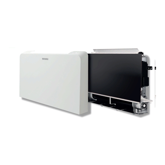
    Leistungsmerkmalen, zu diesem Gebrauch bestimmt. • Dieses Gerät ist nur für den Hausgebrauch oder ähnliche Zwecke bestimmt. • Der unsachgemäße Gebrauch des Geräts enthebt OLIMPIA SPLENDID von jeglicher Haftung für Schäden an Personen, Gegenständen und Tieren. 1 - BESCHREIBUNG DES GERÄTS (Abb. 1) Die Gebläsekonvektoren der Baureihe unterteilen sich in die zwei Grundtypen SL und SLR, die jeweils in...
  • Seite 46: Geräteabmessungen

    In Räumen mit Öldämpfen WARNHINWEIS Die Missachtung der genannten Vorschriften kann zu Betriebsstörungen des Geräts führen, wobei die Firma OLIMPIA SPLENDID keine Garantie und für etwaige Schäden an Personen, Tieren oder Gegenständen keinerlei Haftung übernimmt. Sicherstellen, dass: a. Die Wand/Decke oder Boden, an der das Gerät installiert werden soll, muss eine angemessene Beschaffenheit und Tragfähigkeit aufweisen;...
  • Seite 47: Installationshinweis

    Es wird angeraten, dem Gerät eine angemessene Neigung in Richtung der Drainageleitung zu verleihen, f. Sämtliche 6 Befestigungsschrauben endgültig anziehen. Für die Installation der Ausführungen SL sind als Zubehör die Bausätze waagrechte Kondenswasser- Auffangschale erhältlich. DE - 9 Bi2 Air...
  • Seite 48: Hydraulischer Anschluss

    2.6 - HYDRAULISCHER ANSCHLUSS 2.6.a - Rohrleitungsdurchmesser Der für die Leitungen der Wasseranschlüsse einzuhaltende Mindest-Innendurchmesser variiert von Modell zu Modell: SLR/SL 200 ø12 mm SLR/SL 800 ø18 mm SLR/SL 400 ø14 mm SLR/SL 1000 ø20 mm SLR/SL 600 ø16 mm 2.6.b - Anschluss an das Rohrleitungsnetz Die Wahl und die Bemessung der Rohrleitungen obliegt dem Installateur, der fachmännisch und unter Befolgung der geltenden Vorschriften vorgehen muss.
  • Seite 49: A - Anschluss Der Kondensatwasserleitung An Geräten Zur Wand- Oder Senkrechter Montage

    Für den Anschluss des Motors, des Displays und des Klappenmotors die eigens vorgesehene, als Zubehör erhältliche Verkabelung für rechtsseitige Anschlüsse, verwenden. e. Die Kondenswasser-Auffangschale (7) demontieren und auf der gegenüberliegenden Seite mit den entsprechenden Befestigungsschrauben (7a) wieder montieren. DE - 11 Bi2 Air...
  • Seite 50: C - Drehen Des Wärmetauschers (Abb.16-17)

    2.8.c - Drehen des Wärmetauschers (Abb.16-17) a. Die vier Schrauben (27a) abschrauben, die den unteren Wärmetauscher befestigen; b. Den Temperatursensor vom Wärmetauscher lösen c. Den Wärmetauscher (27) herausziehen; d. Die Tropfenfängerverlängerung (17) aus der mittleren Schale herausziehen; e. Auf der gegenüberliegenden Seite, den Stopfen (17a) von der Kondenswasser-Ablauföffnung abziehen; f.
  • Seite 51 Die drei Wahlschalter können in allen möglichen Kombinationen versetzt werden, da die jeweiligen Funktionen voneinander unabhängig sind. Bei jedem Einschalten zeigt das Display 5 Sekunden lang den der Einstellung der inneren Wahlschalter entsprechenden Code an: DE - 13 Bi2 Air...
  • Seite 52: B - Standby Kontakt

    2.11.b - Standby Kontakt An die Klemmen „A“ und „B“ (Abb. 20A-20b) kann der potentialfreie Kontakt eines etwaigen Anwesenheitssensors (nicht im Lieferumfang enthalten) angeschlossen werden, bei dessen Schließen das Gerät deaktiviert wird (Werkseinstellung: Standby). Es ist möglich, im Werk oder beim Kundendienst nach vorheriger Anfrage des Kunden diese Funktion derart zu ändern, dass bei Schließen des Kontakts automatisch die gewählte Raumtemperatur um einen Um diese Funktion zu nutzen, kontrollieren, dass die Klemmen „A“...
  • Seite 53: Bedienung

    Einstellung programmierte Ausschaltung des Geräts • 10: Heizmodus aktiv • B10: Bestätigung bzw. Löschung des programmierten • 11: Kühl-Modus aktiv Ein- bzw. Ausschaltens des Geräts °F °F °C °C SWING MODE NIGHT A5 A4 A3 A2 A1 DE - 15 Bi2 Air...
  • Seite 54: Verwendung Der Fernbedienung

    3.3 - VERWENDUNG DER FERNBEDIENUNG Die mit dem Gerät gelieferte Fernbedienung wurde derart entworfen, dass sie möglichst strapazierfähig und praktisch ist, gleichwohl ist sie mit einigen Vorsichtsmaßnahmen zu handhaben. Vermeiden: • Sie dem Regen auszusetzen, Flüssigkeiten über die Tastatur zu gießen oder ins Wasser fallen zu lassen; •...
  • Seite 55: Manueller Kühl- Bzw. Heiz-Modus

    (A4) drücken. wie in der Heizung (der Lüftermotor wird immer bei höchster Geschwindigkeit aktiviert). Verwendung der Fernbedienung a. Um diesen Betriebsmodus zu wählen, mehrmals die Taste „B6“ bis zur vollständigen Aktivierung der Anzeige (6) drücken. DE - 17 Bi2 Air...
  • Seite 56: B - Betrieb Mit Automatischer Wahl Der Gebläsestufe

    3.6.b - Betrieb mit automatischer Wahl der Gebläsestufe Verwendung des Bedienfelds am Gebläsekonvektor a. Um diesen Betriebsmodus zu wählen, mehrmals die Taste „ “ (T2) bis zur Aktivierung der Anzeige (A3) drücken. b. In diesem Betriebsmodus erfolgt die Regelung der Lüftergeschwindigkeit vollkommen automatisch zwischen einem Mindest- und einem Höchstwert, je nach der Heiz- bzw.
  • Seite 57: Swing-Funktion Der Luftausblassklappe

    Das Display der Fernbedienung zeigt den Countdown für das Einschalten an, während das Display des Bedienfelds am Gerät den Schriftzug „tl“ anzeigt. Nach Ablauf der eingestellten Zeit wird das Gerät mit den letzten Einstellungen gestartet. 6.0 H DE - 19 Bi2 Air...
  • Seite 58: B - Einstellung Des Timers „Aus" Mittels Der Fernbedieung

    3.11.b - Einstellung des Timers „Aus“ mittels der 3.0 H Fernbedieung a. In jeder beliebigen Betriebsweise des Geräts die Taste „B9“ drücken, um die gewünschte Verzögerung einzustellen (zwischen 1 und 24 Stunden), nach der sich das Gerät abschaltet (ab der Bestätigung des Timers).
  • Seite 59: Ratschläge Zur Einergieeinsparung

    - Soweit wie möglich, die Türen und Fenster des zu klimatisierenden Raums geschlossen halten; - Im Sommer so weit wie möglich, das Eindringen von direkten Sonnenstrahlen in die zu klimatisierenden Räume beschränken (Vorhänge, Fensterläden usw. verwenden). DE - 21 Bi2 Air...
  • Seite 60: Technische Daten

    5 - TECHNISCHE DATEN Modelle 1000 Beschreibung Wasserinhalt des 0,47 0,80 1,13 1,46 1,80 Wärmetauschers Wasserinhalt des patentierten 0,19 0,27 0,35 0,43 Wärmestrahlungselements °C Wassereintrittstemperatur Mindest- °C Wassereintrittstemperatur Eurokonus Eurokonus Eurokonus Eurokonus Eurokonus Wasseranschlüsse Versorgungsspannung: Gewicht SL 11,5 15,5 18,5 21,5 Gewicht SLR 13,5...
  • Seite 61 - Der Lüfter berührt den Geräteauf- - Die eventuellen Berührungspunk- bau. te durch Drehen des Lüfters von Hand überprüfen. - Die Unwucht verursacht übermä- - Der Lüfter ist aus dem Gleichge- ßige Schwingungen des Geräts: wicht geraten. Den Lüfter auswechseln. DE - 23 Bi2 Air...
  • Seite 62 STÖRUNG URSACHE ABHILFE FI: Der Gebläsekonvektor erfordert - Das Stand-by-Programm wählen eine Wartung. Wartungsanleitung des Geräts beschreiben - Das Gerät erneut einschalten und 5 Sekunden lang die Tasten „T2“ und „T3“ bis zur Wiederherstellung des normalen Betriebs gedrückt halten. E2: Zeigt das Vorliegen eines - Den Kundendienst benachrichti- Defekts der Raumtemperatursonde E 3 i s t a n d e n D e f e k t d e r...
  • Seite 63 3.6 - FAN MODE ...........................17 3.6.a - Operation at maximum speed ......................17 3.6.b - Operation at AUTO speed ......................18 3.7 - NIGHT OPERATION ........................18 3.8 - MEANING OF BLINKING AND OPERATION OF THE LED ............18 EN - 1 Bi2 Air...
  • Seite 64 3.9 - SWING OPERATION ........................19 3.10 - SPECIAL FUNCTIONS .........................19 3.10.a - Air sampling ..........................19 3.10.b - Commands lock ..........................19 3.11 -OPERATION WITH TIMER (DELAYED SWITCHING ON AND SWITCHING OFF) ......19 3.11.a - Setting of the switching on timer from remote controller .............19 3.11.b - Setting of the switching off timer from remote controller .............20 3.12 - SWITCHING OFF FOR PROLONGED PERIODS ................20...
  • Seite 65: General Information

    - refusal of liability by the manufacturer. Raised hand Refers to actions that absolutely must not be performed. DANGER OF HIGH VOLTAGE Signals to the personnel that the operation described could cause electrocution if not performed according to the safety rules. EN - 3 Bi2 Air...
  • Seite 66: General Warnings

    1. This document is restricted in use to the terms of the law and may not be copied or transferred to third parties without the express authorization of the manufacturer, OLIMPIA SPLENDID. any way. 2. Read this manual carefully before performing any operation (installation, maintenance, use) and follow the instructions contained in each chapter.
  • Seite 67 9. In case of replacement of parts, use only original OLIMPIA SPLENDID parts. 10. Do not disconnect power supply during operation.
  • Seite 68 29. The appliance can reach temperatures higher than 70°C on the external components. PAY PARTICULAR ATTENTION TO CONTACT, DANGER OF BURNS. 30. OLIMPIA SPLENDID’s fan radiators/fan coils are compliant with the European Directives: • Low voltage directive 2014/35/EU • Electromagnetic compatibility directive 2014/30/EU.
  • Seite 69: Intended Use

    • This appliance is only destined for domestic use or similar. • An improper use of the appliance with possible damages caused to people, property or animals relieves OLIMPIA SPLENDID from any liability. 1 - APPLIANCE DESCRIPTION (Fig.1) The fan radiators/fan coils of the array are divided into two base types SL and SLR, each of which has been built in models of different performances and dimensions.
  • Seite 70: Overall Dimensions

    WARNING A failure to apply the indicated standards, which may cause malfunctioning of the equipment, relieves the company OLIMPIA SPLENDID from any form of warranty and from possible damages caused to people, animals or property. Make sure that: a.
  • Seite 71: Mode Of Installation

    Ensure their stability by manually moving the brackets rightwards and leftwards, up and down. 2.5 - ROOF OR HORIZONTAL INSTALLATION (only for SL) For installation of the SL versions, the horizontal condensation collection basin kits are available as accessories. EN - 9 Bi2 Air...
  • Seite 72: Water Connections

    2.6 - WATER CONNECTIONS 2.6.a - Pipelines diameter The minimum internal diameter which must be respected for the pipelines of the water connections varies depending on the model: SLR/SL 200 ø12 mm SLR/SL 800 ø18 mm SLR/SL 400 ø14 mm SLR/SL 1000 ø20 mm SLR/SL 600 ø16 mm...
  • Seite 73: Rotation Of Connections

    Disconnect the connectors of the electrical connections. c. Remove the wiring inside the machine and reinsert them on the opposite side. as an accessory. e. Dismount the condensation collection basin (7) and remount it on the opposite side with the corre- EN - 11 Bi2 Air...
  • Seite 74: Filling The System

    a. Undo the four screws (27a) which secure the lower heat exchanger; b. Remove the water probe of the battery c. Remove the heat exchanger (27); d. Remove the drip edge extension (17) from the central basin; e. On the opposite side, remove the cap (17a) on the condensation discharge hole; side so as that the connection for the drip edge extension protrudes from the structure and then lock the basin with the previously dismounted screw (27b);...
  • Seite 75 The three selectors can be positioned in all the possible combinations since the respective functions are independent from each other. At each reactivation, the display shows the code corresponding to the setting of the internal selectors for 5 seconds: EN - 13 Bi2 Air...
  • Seite 76: B - Presence Contact Input

    2.11.b - Presence contact input To terminals “A” and “B” presence sensor (not supplied) which, when closed, causes the deactivation of the appliance (factory setting stand-by). It is possible, in factory or an authorized assistance centre upon prior request of the customer, to change this function so that the selected ambient temperature is automatically increased (in cooling mode) or To use this function, check that the terminals “A”...
  • Seite 77: Use Of The Appliance

    Swing mode active • B9: Unit programmed switching off setting • 10: Heating mode active • B10 • 11: Cooling mode active mation/cancellation °F °F °C °C SWING MODE NIGHT A5 A4 A3 A2 A1 EN - 15 Bi2 Air...
  • Seite 78: Use Of The Remote Controller

    3.3 - USE OF THE REMOTE CONTROLLER The remote controller supplied with the appliance has been designed so as to grant it maximum robustness and exceptional functionality, but it still needs to be handled with care. Avoid: • leaving it exposed to rain, pouring liquids on its keyboard or dropping it in water; •...
  • Seite 79: Manual Cooling/ Heating Mode

    With this mode it is possible to obtain the maximum supplied power both in cooling and heating modes (the fan motor is always active at maximum speed). From remote controller a. To select this mode, press key “B6” several times until the indicator (6) activates completely. EN - 17 Bi2 Air...
  • Seite 80: B - Operation At Auto Speed

    3.6.b - Operation at AUTO speed From board the machine a. To select this mode, press key “ ” (T2) several times until the indicator (A3) activates. b. In this mode, the fan speed adjustment is completely automatic between a minimum and maximum value, according to the heating or cooling needs of the room From remote controller a.
  • Seite 81: Swing Operation

    The remote controller display shows the countdown for switching on while the display of the fan coil shows the message “tI”. Once the set time passes, the unit will start with the last selected set- 6.0 H tings. EN - 19 Bi2 Air...
  • Seite 82: Switching Off For Prolonged Periods

    3.0 H a. With the unit set to any operating mode, press key “B9” to set the desired delay (from 1 to 24 hours) after which the unit will switch off b. If no key is pressed within 5 seconds, the timer setting function will end automatically.
  • Seite 83: Advices For Energy Conservation

    (42) must support the clip (42a) inside the front panel. 4.2 - ADVICES FOR ENERGY CONSERVATION - Keep the doors and windows of the rooms which must be conditioned closed as much as possible; conditioned (use curtains, blinds, etc.). EN - 21 Bi2 Air...
  • Seite 84: Technical Data

    5 - TECHNICAL DATA Models 1000 Description Battery water 0,47 0,80 1,13 1,46 1,80 content Radiant panel water 0,19 0,27 0,35 0,43 content Maximum operating pressure Water delivery maximum temperature Water delivery minimum temperature Water Eurokonus Eurokonus Eurokonus Eurokonus Eurokonus connections Power voltage...
  • Seite 85 - The fan is unbalanced. - U n b a l a n c i n g d e t e r m i n e s excessive vibrations of the machine: replace the fan. EN - 23 Bi2 Air...
  • Seite 86 MALFUNCTION CAUSE SOLUTION FI: The fan coil needs maintenance. - Select the program stand-by on the maintenance manual of the machine - Switch the unit on and keep keys “T2” and “T3” pressed for 5 seconds until normal operation is restored. E2: indicates the presence of a - Contact the assistance failure in the ambient temperature...
  • Seite 88 279930F...

Inhaltsverzeichnis