Werbung
Verfügbare Sprachen
Verfügbare Sprachen
Quicklinks
Steckbare Lasttrennleisten mit Sicherungen
Betriebsanleitung
Berührungsschutz
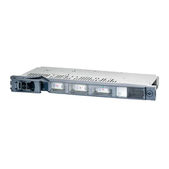
Frontansicht
Geräte für den Hilfs-
stromkreis
GWA 4NEB 711 6034-12
All manuals and user guides at all-guides.com
Bestell-Nr.: 3ZX1012-0NJ61-2AN1
Nach IEC 60529, DIN 50 050
Schutzart im Betriebszustand: IP 41
Inbetriebsetzung und Wartung nur durch Fachpersonal.
Beachten Sie die Betriebsanleitung!
WARNUNG
Gefährliche elektrische Spannung.
Kann zu elektrischem Schlag und Verbren-
nungen führen.
Vor Beginn der Arbeiten Anlage und Gerät
spannungsfrei schalten.
Siehe auch Betriebsanleitungen:
3NJ6110 (Bestell-Nr.: 3ZX1012-0NJ61-1AN1)
3NJ6120 (Bestell-Nr.: 3ZX1012-0NJ62-1AN1)
3NJ6140 (Bestell-Nr.: 3ZX1012-0NJ64-1AN1)
3NJ6160 (Bestell-Nr.: 3ZX1012-0NJ64-1AN1)
3NJ6913 (Bestell-Nr.: 3ZX1012-0NJ63-1AN1)
Bild 1: Fontansicht mit gesteckten Leisten und teilweise entfernten Geräten mit Blick auf
Steckschienen
Direkt im Schaltgerät ist Platz für ein Amperemeter 48 X 48 (siehe Bild 1).
DIN VDE 0660 Teil 107, IEC 60947-3
Blindabdeckung
Überwachungsanzeige
(z.B. Amperemeter)
3NJ6
Deutsch
1
Werbung

Verwandte Anleitungen für Siemens 3NJ6


Inhaltszusammenfassung für Siemens 3NJ6
- Seite 1 All manuals and user guides at all-guides.com Steckbare Lasttrennleisten mit Sicherungen 3NJ6 DIN VDE 0660 Teil 107, IEC 60947-3 Betriebsanleitung Bestell-Nr.: 3ZX1012-0NJ61-2AN1 Deutsch Nach IEC 60529, DIN 50 050 Berührungsschutz Schutzart im Betriebszustand: IP 41 Inbetriebsetzung und Wartung nur durch Fachpersonal.
- Seite 2 All manuals and user guides at all-guides.com Hilfsschalter 3NJ6912.. Die Hilfsschalteranschlüsse der steckbaren Sicherungsleiste lie- gen im rechten hinteren Gerätebe- reich und sind vom Kabel- anschlussraum zugängig (siehe Bild). Der Anschluss erfolgt mit Flachstecker 6,3 X 0,8 mm. Elektrischer Aufbau Geräte für den Hauptstromkreis Bild 2: Elektrischer Aufbau a Sicherungsmodul für Sicherungen der Größen NH 00, 1, 2 und 3...
- Seite 3 All manuals and user guides at all-guides.com ACHTUNG Anschluss bei Baugröße 00 Die nachträgliche Montage von Kabelklemmen ist für die Baugröße 00 nicht möglich! Bei Verwendung von Messwandlern für die Baugröße 00 werden durch den Einsatz von Gerä- ten mit Kabelklemmen die Anschlussarbeiten erleichtert. Ein Leiter von 10 mm muss durch Biegen um 180°...
- Seite 4 All manuals and user guides at all-guides.com Bild 9: Baugrößen 2 und 3, Bild 10: Baugröße 00 mit Doppelte Kabelklemmenausführung Anschlussabdeckung 3NJ6913-1AA00 Bild 11: Baugröße 1 mit Bild 12: Baugrößen 2 und 3 mit Anschlussabdeckung 3NJ6913-1BA00 Anschlussabdeckung 3NJ6913-1CA00 Schalthebel zum Ein- klappen entriegeln Die dünnere Griffleiste bis zum Anschlag in Richtung Griff ziehen...
- Seite 5 All manuals and user guides at all-guides.com Gerätedeckel entriegeln Das Betätigungswerkzeug in 90° Stellung zum Gerätedeckel senk- recht ansetzen und in die Kerbe einschieben bis Widerstand spür- bar. Danach das Werkzeug herun- terdrücken, bis die Verriegelung der Klappe freigegeben wird (siehe Bild).
- Seite 6 All manuals and user guides at all-guides.com Zum Ziehen der Lasttrennleisten gehen Sie wie folgt vor: Ziehen der Lasttrennlei- sten Schritt Vorgehenweise Abzweig freischalten und Spannungsfreiheit an den Anschlusskabeln prüfen (dazu ggf. Abdeckungen zurückziehen). NH-Sicherungen ziehen. Anschlusskabel vom Hauptstromkreis lösen und ggf. zurückbinden. Hilfsanschlüsse (soweit vorhanden) zum feststehenden Teil des Feldes lösen.
- Seite 7 All manuals and user guides at all-guides.com Zum Ziehen der Sicherungsleiste der Baugrößen 1, 2 und 3 fahren Sie wie folgt fort: Schritt Vorgehenweise Den offenen Geräte- deckel (ca. 90° zur Front) durch einen Schlag mit dem Hand- ballen von links außen in Scharniernähe aus dem Scharnier lösen, dabei mit der zweiten...
- Seite 8 All manuals and user guides at all-guides.com Anbau von Blindabdeckungen: Zubehör 50 mm 3NJ6916-4AA00 100 mm 3NJ6916-4DA00 Die Blindabdeckungen aus Kunststoff sind links und rechts mit je 1 Schraube M6 mit einem Drehmoment von max. 8 Nm auf dem Blechhalter zu verschrauben. Einbau von Messwand- Meßwandler können 1-phasig und 3-phasig eingebaut werden.
- Seite 9 All manuals and user guides at all-guides.com Bild 17: Baugröße 2 und 3, Lage des Bild 18: Baugröße 2 und 3, Lage des Messwandlers 1-phasig Messwandlers 3-phasig 3ZX1012-0NJ61-2AN1...
- Seite 10 All manuals and user guides at all-guides.com 3NJ6 Maßbilder 3-polig 12,5 Loch für Befestigungs- schraube 3NJ6110, Baugröße 00 3NJ6120, Baugröße 1 Führungs- Steckkontakt stift 3NJ6140 und 3NJ6160, Baugrößen 2 und 3 Anschlussabdeckungen 3NJ6913-1CA00, Baugrößen 2 und 3 3NJ6913-2BA00, Baugröße 1 3NJ6913-1AA00, Baugröße 00...
- Seite 11 All manuals and user guides at all-guides.com Maßbilder 4-polig 12,5 77,5 97,5 Baugröße 00 Baugröße 1 Baugrößen 2 und 3 3ZX1012-0NJ61-2AN1...
- Seite 12 All manuals and user guides at all-guides.com 3NJ6911-3AA00 (Baugröße 00) Kontaktverlängerungen 77,5 3NJ6911-3BA00 (Baugröße 1) 83,5 3NJ6911-3CA00 (Baugrößen 2 und 3) Baugröße 00 Kabelanschlüsse mit Kabelklemmenanschluß für Stehbolzenanschluß 3ZX1012-0NJ61-2AN1...
- Seite 13 Baugrößen 2 und 3 mit Kabelklemmenanschluß für Stehbolzenanschluß Technical Support: Tel: ++49 (0) 9131-7-43833 (8°° - 17°° MEZ) Fax: ++49 (0) 9131-7-42899 E-mail: NST.technical-support@erl7.siemens.de Internet: www.ad.siemens.de/support Bestell-Nr./Order No.: 3ZX1012-0NJ61-2AN1 Technische Änderungen vorbehalten. Subject to change without prior notice. © Siemens AG 2000...
- Seite 14 All manuals and user guides at all-guides.com Plug-in in-line fuse switch-disconnectors 3NJ6 DIN VDE 0660 Part 107, IEC 60947-3 Instructions Order No.: 3ZX1012-0NJ61-2AN1 English Degree of protection to IEC 60529, DIN 50 050 Safety from finger-touch Degree of protection during operation: IP41 Commissioning and maintenance by qualified persons only.
- Seite 15 All manuals and user guides at all-guides.com Auxiliary switch 3NJ6912.. Auxiliary switch terminals of the plug-on in line-type fuse switches are located in the right-hand rear area for the switching device and are accessi- ble from the cable connection department (see Fig.). Auxiliaries are connected with flat-pin plug 6,3 x 0,8 mm.
- Seite 16 All manuals and user guides at all-guides.com Caution! Connection of size 00 For size 00, retrofitting of cable terminals is not possible. Where measuring current transfor- mers are used for size 00, the use of switching devices with cable terminals simplifies con- nection work.
- Seite 17 All manuals and user guides at all-guides.com Fig. 9: Sizes 2 and 3, double cable terminal Fig. 10 Size 00, with cover 3NJ6913-1AA0 Fig. 11: Size 1, general Fig. 12: Sizes 2 and 3, with cover 3NJ6913-1BA0 with cover 3NJ6913-1CA0 Unlocking the grip to fold-away Pull the slim grip outwards as far...
-
Seite 18: Maintenance
All manuals and user guides at all-guides.com Unlocking the switching device flap Unlocking the switching device flap by blade in position "I": Attach the tool at a position of 90° vertical to the cover and push it into the notch until resistance is felt. - Seite 19 All manuals and user guides at all-guides.com To remove the in-line fuse switch-disconnector proceed as follows: Pulling the in-line fuse switch-disconnectors Step Procedure Isolate feeder and verify dead state at the connecting cables (pull bach covers if necessary). Pull LV HRC fuses. Undo connecting cables from main circuit and tie back if necessary.
- Seite 20 All manuals and user guides at all-guides.com Further steps to remove the in-linefuse switch-disconnector sizes 1, 2 and 3: Step Procedure Strike the open device cover (at an angle of approx. 90° to the front) with the edge of your hand on the outer left-hand side near the hinge, so as to remove it from the hinge.
- Seite 21 All manuals and user guides at all-guides.com Fitting plastic blanking covers: Accessories 50 mm 3NJ6916-4AA00 100 mm 3NJ6916-4DA00 Fit the plastic blanking covers to the metal holder with one M6 screw on the left and right hand sides each, applying a max. tightening torque of 8 Nm. Fitting measuring Single or three-phase measuring current transformers can be retrofitted.
- Seite 22 All manuals and user guides at all-guides.com Fig. 17 Sizes 2 and 3, position af 1-phase Fig. 18: Sizes 2 and 3, position of 3-phase measuring current transformer measuring current transformer 3ZX1012-0NJ61-2AN1...
- Seite 23 All manuals and user guides at all-guides.com 3NJ6 Dimension drawings, 3-pole 12,5 Hole for mounting srew 3NJ6110, size 00 3NJ6120, size 1 Plug-type contact Guide pin 3NJ6140 and 3NJ6160, sizes 2 and 3 Covers 3NJ6913-2CA00, sizes 2 and 3 3NJ6913-2BA00, size 1 3NJ6913-1AA00, size 00 m ax.
- Seite 24 All manuals and user guides at all-guides.com Dimension drawings, 4-pole 12,5 77,5 97,5 Size 00 Size 1 Sizes 2 und 3 3ZX1012-0NJ61-2AN1...
- Seite 25 All manuals and user guides at all-guides.com 3NJ6911-3AA00 (size 00) Contact extensions 77,5 3NJ6911-3BA00 (size 1) 83,5 3NJ6911-3CA00 (sizes 2 und 3) Size 00 Cable connections With cable clamp connection For stud terminal 3ZX1012-0NJ61-2AN1...
- Seite 26 For cable clamp connection For stud terminal Technical Support: Tel: ++49 (0) 9131-7-43833 (8°° - 17°° MEZ) Fax: ++49 (0) 9131-7-42899 E-mail: NST.technical-support@erl7.siemens.de Internet: www.ad.siemens.de/support Bestell-Nr./Order No.: 3ZX1012-0NJ61-2AN1 Technische Änderungen vorbehalten. Subject to change without prior notice. © Siemens AG 2000...