Herunterladen Inhalt Inhalt Diese Seite drucken
Schulthess proLine D200 Aufstellanleitung

Schulthess proLine D200 Aufstellanleitung

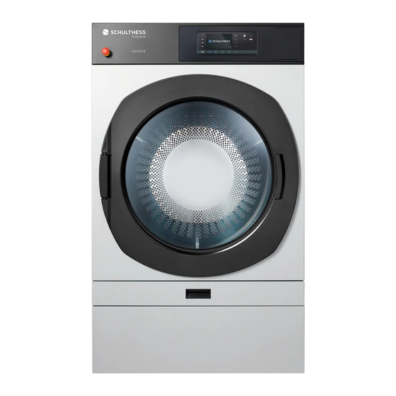
Professioneller wäschetrockner
Vorschau ausblenden Andere Handbücher für proLine D200:

Werbung

Verfügbare Sprachen

Verfügbare Sprachen

Professioneller Wäschetrockner
Sèche-linge professionnel
Asciugatrice professionale
Professional dryer
Aufstellanleitung
Notice d'installation
Istruzioni per l'installazione
Installation instruction
proLine
D 200 | D 325

Werbung

Inhaltsverzeichnis
loading

Inhaltszusammenfassung für Schulthess proLine D200

  • Seite 1 Professioneller Wäschetrockner Sèche-linge professionnel Asciugatrice professionale Professional dryer Aufstellanleitung Notice d’installation Istruzioni per l’installazione Installation instruction proLine D 200 | D 325...
  • Seite 3: Inhaltsverzeichnis

    Inhalt / Sommaire / Indice / Content DEUTSCH Sicherheit und Schutzmassnahmen . . . . . . . . . . . . . . . . 5 Gerät aufstellen .
  • Seite 4: Deutsch

    DEUTSCH Symbole Vor Gebrauch des Gerätes die Anleitungen lesen Warnhinweise sind mit einem Warndreieck gekennzeichnet . Es wird angegeben, wie die Gefahr vermieden werden kann. Signalwörter kennzeichnen die Schwere der Gefahr, die auftritt, wenn sie nicht vermieden wird . Warnung bedeutet, dass Personenschäden, unter Umständen auch lebensgefährliche Verletzungen auftreten können .
  • Seite 5: Sicherheit Und Schutzmassnahmen

    Sicherheit und Schutzmassnahmen Die beiliegenden Anleitungen enthalten wich- Beim Betreiben des Trockners im Freien tige Informationen zu Installation, Gebrauch besteht Kurzschluss- bzw . Brand gefahr . und Sicherheit des Wäschetrockners . Stellen Sie das Gerät nicht im Freien auf . ►...
  • Seite 6: Gerät Aufstellen

    Gerät aufstellen Gerät an Aufstellort transportieren Hinweis Um den Trockner an den Aufstellort zu bringen, kann Kleine geschlossene Räume ohne Be- und Ent- er mit einem Hubwagen unterfahren werden . Das lüftungs möglichkeit sind nicht geeignet als Aufstel- Einbringen durch Türen mit einer Breite von 80 cm ist lort .
  • Seite 7: Aufstellfläche

    Frontabdeckung und Schublade wieder Gerätemasse beachten einsetzen Hinweis Das Gerät kann mit seiner Rückseite gegen eine Wand gestellt werden . Der Mindestabstand zwischen dem Gerät und einer Wand beträgt 50 cm . 79 cm Schrauben Sie die Frontabdeckung nach dem Trans- ►...
  • Seite 8: Frischluft-Anschluss (Option)

    Abluftleitung Als Abluftleitung können verschiedene handelsübliche Produkte verwendet werden: • Kunststoffrohre • Flexible Kanäle / flexible Rohre • Blechkanäle / Blechrohre, verzinkt • Verbindungs- / Übergangs- / Umlenkstücke für Flach- Lösen Sie die Kontermuttern der Gerätefüsse mit ► kanal- oder Rohrsystem einem Schraubenschlüssel .
  • Seite 9: Aussenluftgitter

    Gesamten Druckverlust berechnen D 200 Beladung 11 kg Maximaler Volumenstrom 480 m Maximaler Leitungswiderstand, bauseitig 200 Pa Abluftanschluss, Durchmesser 160 mm (Option) 200 mm Gerade, glatte Rohre Druckverlust pro Meter 4 Pa 2 Pa Gebogene Rohre, glatt (rm = 1,5 d) 30°-Bogen 2 Pa 2 Pa...
  • Seite 10: Elektrischer Anschluss

    Elektrischer Anschluss Warnung Werden im Aufstellraum oder in benachbarten Räumen zusätzliche Geräte wie Gasheizungen, Gas- Hinweis Durchlauf erhitzer, Kohleöfen mit Kaminanschluss Der Anschluss an die Strom versorgung muss durch oder offene Kamine betrieben, kann Unterdruck ent- eine Fachperson ausgeführt werden . stehen und ein Rücksaugen von Abgasen bewirken .
  • Seite 11 11 kg-Wäschetrockner 400 V 3 N ~ 15 kW N L1 L2 L3 N L1 L2 L3 Heizung 14,4 kW Motor 0,6 kW Sicherung 25 AT 18 kg-Wäschetrockner 400 V 3 N ~ 21,2 kW N L1 L2 L3 N L1 L2 L3 Heizung 20,6 kW Motor...
  • Seite 13: Beschrieb Zu Installationsplan

    Beschrieb zu Installationsplan Elektroanschluss Flexibel, gemäss Anschlussschema Optionen: Netzperrset Potenzialfreier Lüftungskontakt Hauptschalter Not-Aus-Taste Schilder Typenschilder, Leistungsschild, Warnschild, Serviceschild Abluft-Anschluss Durchmesser 200 mm Option: 160 mm Abluftmenge D 200: max . 480 m D 325: max . 840 m Ablufttemperatur max . 70 °C Leitungswiderstand bauseitig D 200: max .
  • Seite 14: Français

    Français Symboles Lire les instructions avant d’utiliser l’appareil. Les avertissements de sécurité sont précédés d’un triangle de signalisation. Il est indiqué comment éviter le danger. Les avertissements caractérisent la gravité du danger qui survient si celui-ci n›est pas évité . Avertissement indique que de graves dommages corporels, voir même un danger de mort peuvent survenir .
  • Seite 15: Sécurité Et Mesures De Protection

    Sécurité et mesures de protection Les instructions ci-joint contiennent des En cas d’utilisation de la machine en exté- informations importantes sur l’installation, rieur, il existe un risque de court-circuit et l’utilisation et la sécurité du sèche-linge . d’incendie . ► Conservez-les soigneusement pour les autres ►...
  • Seite 16: Installer L'appareil

    Installer l’appareil Transporter l’appareil sur le lieu d’installation Remarque Pour amener le séchoir sur le site d’installation, il Les petites pièces fermées sans aération ne peut être placé sur un chariot élévateur . Il peut être conviennent pas à l’installation d’un sèche-linge . facilement inséré...
  • Seite 17: Emplacement D'installation

    Remplacer la façade et le tiroir Observer les dimensions de l’appareil Remarque La machine peut être installée avec sa paroi arrière contre un mur . La distance minimale entre l’appareil et le mur ou un éventuel appareil adjacent est de 50 cm .
  • Seite 18: Raccord D'air Frais (En Option)

    Conduite d’évacuation de l’air Pour la conduite d’évacuation d’air, vous pouvez utiliser tous les produits en usage dans le commerce, tels que: • des tuyaux en matière plastique • des conduits ou tuyaux souples • des conduits ou des tuyaux en tôle zinguée •...
  • Seite 19 Calculer la perte de pression totale D 200 Chargement 11 kg Débit max . 480 m Résistance des conduites max . (fourni par le client) 200 Pa Raccord de sortie d’air, diamètre 160 mm (option) 200 mm Tuyaux droits et lisses Perte de pression par mètre 4 Pa 2 Pa...
  • Seite 20: Raccordement Électrique

    Raccordement électrique Possibilité d’écoulement pour l’eau de condensation A l’emplacement le plus bas de la conduite d’évacua- tion d’air, on recommande de placer un «collecteur Remarque d’eau de condensation» (en usage dans le commerce) Le branchement de l’appareil au réseau doit être ou un orifice d’écoulement d’environ 3mm de diamètre .
  • Seite 21 Sèche-linge de 11 kg 400 V 3 N ~ 15 kW N L1 L2 L3 N L1 L2 L3 Chauffage 14,4 kW Moteur 0,6 kW Fusible 25 AT Sèche-linge de 18 kg 400 V 3 N ~ 21,2 kW N L1 L2 L3 N L1 L2 L3 Chauffage 20,6 kW...
  • Seite 23: A Décrit Au Plan D'installation

    A décrit au plan d’installation Raccordement électrique Flexible selon plan de raccordement Options: Kit de blocage réseau Contact d’aération sans potentiel Disjoncteur principal Touche d’arrêt d’urgence Plaquettes Plaques signalétiques, plaque de puissance, panneau avertisseur, plaque de service Raccord de sortie d’air Diamètre 200 mm Option: 160 mm...
  • Seite 24: Italiano

    ITALIANO Simboli Leggere le istruzioni prima di utilizzare l’apparecchio Le avvertenze sono contrassegnate da un triangolo di avvertimento . Indicano come evitare il pericolo incombente . Le parole di segnalazione indicano la gravità del pericolo che può verificarsi se non viene evitato questo pericolo .
  • Seite 25: Sicurezza E Misure Preventive

    Sicurezza e misure preventive Le istruzioni allegate contengono importanti L’uso dell’asciugatrice in spazi esterni può informazioni sull’installazione, l’uso e la sicu- provocare cortocircuiti e/o incendi . rezza dell’asciugatrice . L’apparecchio non deve essere posizionato in ► ► Conservarle con cura per gli altri utenti o per spazi aperti .
  • Seite 26: Installazione Dell'apparecchio

    Installazione dell’apparecchio Trasportare l’apparecchio sul luogo Avviso d’installazione Gli ambienti piccoli e chiusi che non offrono la possi- L’asciugatrice può essere portata sul luogo d’installa- bilità di ventilazione e scarico dell’aria non sono adatti zione con un carrello elevatore . Può passare facilmen- per installare l’apparecchio .
  • Seite 27: Livellamento Dell'apparecchio

    Riapplicare la copertura e il cassetto Attenersi alle misure dell’apparecchio Avviso Il pannello posteriore dell’apparecchio può essere posizionato contro una parete . La distanza minima obbligatoria tra l’apparecchio e la parete, oppure da un altro apparecchio, deve essere di 50 cm . 79 cm Riavvitare la copertura dopo il trasporto .
  • Seite 28: Attacco Del Tubo Dell'aria Fresca (Opzionale)

    Tubazione per lo scarico dell’aria-vapore Per questa tubazione potete utilizzare i seguenti prodotti in commercio: • Tubi in plastica • Canali flessibili oppure tubi • Canali in lamiera zincata oppure tubi in lamiera • Raccordi, manicotti o raccordi per sistemi di canali Allentare i controdadi con una chiave inglese .
  • Seite 29 Calcolare la perdita di pressione totale D 200 Carico 11 kg Max . volume d’evacuazione aria 480 m Max . resistenza di condotta dalla parte dell’immobile 200 Pa Tubo di scarico dell’aria viziata, diametro 160 mm (opzione) 200 mm Tubi rettilinei, lisci Perdita di pressione al metro 4 Pa 2 Pa...
  • Seite 30: Collegamento Elettrico

    Collegamento elettrico Avvertenza Se nell’ambiente d’installazione o negli ambienti confinanti funzionano altri apparecchi, quali caldaie a Avviso gas o meno, scalda-acqua a gas, stufe a carbone con L’allacciamento elettrico deve essere effettuato sola- collegamento al camino, può verificarsi una depres- mente da un tecnico specializzato .
  • Seite 31 Asciugatrice da 11 kg 400 V 3 N ~ 15 kW N L1 L2 L3 N L1 L2 L3 Riscaldamento 14,4 kW Motore 0,6 kW Valvola di sicurezza 25 AT Asciugatrice da 18 kg 400 V 3 N ~ 21,2 kW N L1 L2 L3 N L1 L2 L3 Riscaldamento...
  • Seite 33: Descrizione Del Piano D'installazione

    Descrizione del piano d’installazione Collegamento elettrico Flessibile, secondo schema d’allacciamento Opzioni: Kit di chiusura rete Contatto di ventilazione a potenziale zero Interruttore principale Tasto per l’arresto d’emergenza Targhe Targhe di identificazione, Targa dei dati di funzionamento, segnale di pericolo, targa di servizio Tubo di scarico dell’aria viziata Diametro 200 mm...
  • Seite 34: English

    ENGLISH Symbols Read the instructions before using the appliance Warnings are marked with a warning triangle . The text gives information how a dangerous situation can be avoided. Signal words indicate the severity of the danger, if not avoided . Warning means that possible personal injuries, and po- tentially life-threatening injuries may occur .
  • Seite 35: Safety And Safety Measures

    Safety and safety measures The enclosed documents contain important There is a risk of short circuits and fire, when information on the installation, use and operating the dryer outdoors . safety of the dryer . The machine must not be operated out- ►...
  • Seite 36: Installing The Appliance

    Installing the appliance Transporting the appliance to the installation Notice site Do not install the dryer in an enclosed area or in any A forklift truck can be driven under the dryer to area without fresh air circulation . transport it to the installation site . It is very easy to bring it through doors with a width of 80 cm .
  • Seite 37: Installation Area

    Re-insert cover and drawer Keep machine dimensions in mind Notice The machine can be placed with its back against a wall . The minimum distance between the machine and the wall or possibly another machine is 50 cm . 79 cm Tighten the screws on the cover after transportation .
  • Seite 38: Fresh Air Connection (Option)

    Exhaust air duct For the exhaust air duct you can use all normal propri- etary products, such as: • Plastic tubes • Flexible ducts or tubes • Galvanised metal ducts or tubes • Connecting, transition or deflection pieces for flat duct Loosen the counternuts with a screw wrench .
  • Seite 39 Calculating the total pressure loss D 200 Load 11 kg Max . flow rate 480 m Max . resistance in the installation, supplied by the customer 200 Pa Exhaust air duct, diameter 160 mm (option) 200 mm Straight smooth pipes Pressure loss per meter 4 Pa 2 Pa...
  • Seite 40: Electrical Connection

    Electrical connection Warning If additional appliances are operated in the room where the appliance is installed or in adjoining rooms, Notice such as gas-fired heating systems, gas-fired in- Connection of the appliance to the power supply must stantaneous water heaters, coal-fired ovens with be carried out by a specialised electrician .
  • Seite 41 11 kg dryer 400 V 3 N ~ 15 kW N L1 L2 L3 N L1 L2 L3 Heating 14,4 kW Motor 0,6 kW Fuse 25 AT 18 kg dryer 400 V 3 N ~ 21,2 kW N L1 L2 L3 N L1 L2 L3 Heating 20,6 kW...
  • Seite 43: Description To Accompany The Installation Plan

    Description to accompany the installation plan Electrical connection Flexible, as per the connection diagramm Options: Power shut-off kit Potential-free ventilation contact Main switch Emergency stop button Labels Type labels, power rating plate, danger sign, service label Exhaust air duct Diameter 200 mm Option: 160 mm Exhaust air volume...
  • Seite 44 Original-Aufstellanleitung Traduction de la notice d’installation originale Traduzione dall‘ originale delle istruzioni per l’installazione Translation of the original installation instruction Instruktions-Nr . 255 306 .AA No . d’instruction No . d’istruzione Instruction no . Produkt-Nummer Numéro de produit Numero di prodotto Product number 4253.1 WT 20...

Diese Anleitung auch für:

Proline d325

Inhaltsverzeichnis