
Verwandte Anleitungen für SW-Stahl 302501L


Inhaltszusammenfassung für SW-Stahl 302501L
- Seite 1 3 0 2 5 0 1 L B E D I E N U N G S A N L E I T U N G D O P P E L- S I L E N T L A G E R W E R K Z E U G...
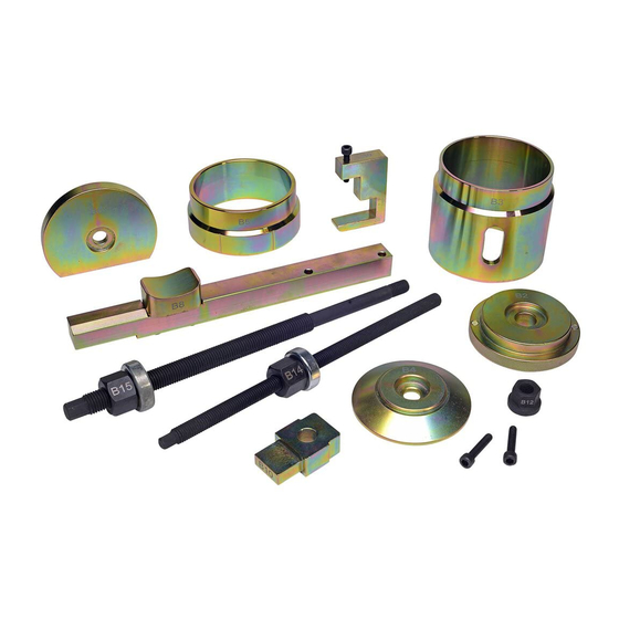
- Seite 2 I N H A LT Nummer Beschreibung Maße Stückzahl Spindel Einbau M12x1.75, 280mmL Druckstück Aus-/Einbau Ø 83mm, 32mmL Glocke Ausbau Ø 106mm, 92mmL Druckstück Ausbau Ø 89mm, 17mmL Konus-Ring Einbau Ø 106 mm, 45mmL Druckstück Einbau Ø 82mm, 15mmL Fixierhalter L280xB22xH22mm Fixierstück L22xB45,5xH31,8mm...
- Seite 3 3 0 2 5 0 1 L A N L E I T U N G : Bitte folgen Sie dieser Betriebsanleitung! Bei nicht sachgemäßer Anwendung kann es zu Zerstörungen der Bauteile, Lager oder Werkzeuge führen, womit die Garantie erlischt. AU S B AU : Vor Beginn der Arbeiten muss die Getriebestütze ausgebaut werden! •...
- Seite 4 E I N B AU : Der Fixierhalter (Nr.7) mit dem Fixierstück (Nr.8) und dem Einstellhalter (Nr.9) bleiben an dem Motor- träger so montiert, wie beim Ausbau. Das Einbauloch sollte vor dem Einbau leicht mit Schmirgelpapier und Fett bearbeitet werden, damit die Lager nicht verkannten. •...
- Seite 5 3 0 2 5 0 1 L • Schritt 5: Nachdem das Doppellager eingebaut ist und alle Werkzeugteile wieder demontiert sind, muss noch der Fixierblock (Nr.10) zwischen den beiden Lagern entfernt werden. Mit dem Einbau der Getriebestütze ist die Arbeit für das Doppellager abgeschlossen.
- Seite 6 N O T I Z E N...
- Seite 7 3 0 2 5 0 1 L 3 0 2 5 0 1 L I N S T R U C T I O N M A N UA L D O U B L E S I L E N T B E A R I N G T O O L...
- Seite 8 I N H A LT Number Description Dimensions Item number Installation of spindle M12x1.75 M12x1.75, 280mmL Removal/Installation of pressure pad Ø 83mm, 32mmL Removal bell Ø 106 mm Ø 106mm, 92mmL Removal of pressure pad Ø 89mm, 17mmL Installation of cone ring Ø 106 mm Ø...
- Seite 9 3 0 2 5 0 1 L D I R E C T I O N S : Please follow these operating instructions! In case of improper application, the destruction of the component parts, bearing or tools can result, where the guarantee is voided. R E M OVA L : Prior to commencement of work, the transmission support stays must be removed! •...
- Seite 10 I N S TA L L AT I O N : The fi xing bracket (No.7) with the fi xing piece (No.8) and the adjusting bracket (No.9) remain assembled on the engine support as in case of removal. The installation hole should be processed lightly with emery paper and grease before the installation, so that the bearing does not tilt.
- Seite 11 3 0 2 5 0 1 L • Step 5: After the bearing has been installed and all the tool parts have been removed the fi xing block (no.10) between the two bearings must be removed. With the installation of the engine support, the work for the double bearing is completed.
- Seite 12 S W- S TA H L G M B H An der Hasenjagd 3 • D-42897 Remscheid Telefon: +49 2191 464380 • Fax: +49 2191 4643840 www.swstahl.de • info@swstahl.de...