Herunterladen Inhalt Inhalt Diese Seite drucken
LD Systems U300 Serie Bedienungsanleitung
Vorschau ausblenden Andere Handbücher für U300 Serie:
Inhaltsverzeichnis

Werbung

Verfügbare Sprachen
  • DE

Verfügbare Sprachen

  • DEUTSCH, seite 16
USER´S MANUAL
BEDIENUNGSANLEITUNG
MANUEL D´UTILISATION
MANUAL DE USUARIO
INSTRUKCJA OBSŁUGI
MANUALE D´USO
U300
®
DIVERSITY WIRELESS SYSTEMS
SERIES

Werbung

Inhaltsverzeichnis

Fehlerbehebung

loading

Inhaltszusammenfassung für LD Systems U300 Serie

  • Seite 1 USER´S MANUAL BEDIENUNGSANLEITUNG MANUEL D´UTILISATION MANUAL DE USUARIO INSTRUKCJA OBSŁUGI MANUALE D´USO U300 SERIES ® DIVERSITY WIRELESS SYSTEMS...
  • Seite 2: Inhaltsverzeichnis

    CONTENTS / INHALTSVERZEICHNIS / CONTENU / CONTENIDO / TREŚĆ / CONTENUTO ENGLISH ESPAÑOL PREVENTIVE MEASURES MEDIDAS DE SEGURIDAD INTRODUCTION INTRODUCCIÓN CONNECTIONS, OPERATING AND DISPLAY ELEMENTS CONEXIONES, ELEMENTOS DE MANEJO Y ELEMENTOS PIN ALLOCATION FOR MINI XLR CONNECTOR DE VISUALIZACIÓN (POCKET TRANSMITTER) ASIGNACIÓN DE PINES PARA CONEXIÓN MINI XLR TROUBLESHOOTING (TRANSMISOR DE PETACA)
  • Seite 3: Preventive Measures

    YOU‘VE MADE THE RIGHT CHOICE! We have designed this product to operate reliably over many years. LD Systems stands for this with its name and many years of experience as a manufacturer of high-quality audio products. Please read this User‘s Manual carefully, so that you can begin making optimum use of your LD Systems product quickly.
  • Seite 4: Introduction

    CAUTION: To reduce the risk of electric shock, do not remove cover (or back). There are no user serviceable parts inside. Maintenance and repairs should be exclusively carried out by qualified service personnel. The warning triangle with lightning symbol indicates dangerous uninsulated voltage inside the unit, which may cause an electrical shock.
  • Seite 5: Connections, Operating And Display Elements

    470 - 490 MHz (LDU3047) 514 - 542 MHz (LDU3051) 584 - 608 MHz (LDU305) 655 - 679 MHz (LDU306) 823 - 832 MHz and 863–865 MHz (LDU308) Please note: The use of the wireless microphone system may require a license, depending on the country of use. For detailed information please contact the relevant authority in your country.
  • Seite 6: Level Indicator

    Rotary knob to adjust the output volume. IR INTERFACE Infra-red interface for synchronising the receiver’s radio channel with the transmitter. To synchronise the transmitter with the radio channel set in the receiver, position the infra-red port of the transmitter directly in line with the infra-red interface of the receiver and switch on the transmitter and receiver (distance about 10 cm, IR interface of the hand transmitter is below the status LED, IR interface of the pocket transmitter on the front side).
  • Seite 7 BALANCED OUTPUT Balanced audio output via 3-pin XLR jack. HAND-HELD TRANSMITTER MICROPHONE HEAD The microphone head is interchangeable, the hand-held transmitter is compatible with the microphone heads from the LD U500® series, available separately. ON / OFF On/off switch. Move the switch to the ON position to turn on the hand-held transmitter, and to the OFF position to turn it off. STATUS LED If the charge status of the batteries is sufficient, the LED lights up green when the hand transmitter is switched on.
  • Seite 8: (Pocket Transmitter)

    POCKET TRANSMITTER ANTENNA Pocket transmitter antenna. For optimum reception, do not cover or kink. IR INTERFACE Infra-red interface for synchronising the radio channel from receiver and transmitter. INPUT 3-pin mini XLR socket to connect a headset, Lavalier or instrument microphone and guitar cable. ON / STANDBY / OFF Switch to activate or deactivate the pocket transmitter (ON = transmitter is switched on, OFF = transmitter is switched off).
  • Seite 9 ATTACHING THE POCKET TRANSMITTER Attach the transmitter to a belt or strap as shown. PIN ALLOCATION FOR MINI XLR CONNECTOR (POCKET TRANSMITTER) MINI-XLR 6,3 mm jack sleeve Guitar, bass and other high-impedance signal sources. MINI-XLR Condenser microphone with internal pull-up resistor. MINI-XLR 2,2k Condenser microphone without internal pull-up resistor.
  • Seite 10: Troubleshooting

    TROUBLESHOOTING PROBLEM SYMPTOM SOLUTION No audio signal or level Receiver: No reception displayed on either antenna Check if the transmitter is turned on. too low A or B. Check the batteries in the transmitter. Receiver: Display lighting is switched off Check the power supply for the receiver and whether the receiver is switched on.
  • Seite 11: Technical Data

    LDU500RK2 – 19" rack mounting kit for the installation of two single receivers (2 rack-mount brackets, 2 connectors and 1 set of screws included). Installation 1. Attach connectors (receiver A on the right-hand side, receiver B on the left-hand side). 2.
  • Seite 12 Signal-to-noise ratio >104dB >104dB >104dB >104dB >104dB (system): Balanced output: Unbalanced output: 6.3 mm jack 6.3 mm jack 6.3 mm jack 6.3 mm jack 6.3 mm jack Audio output level +10dBu +10dBu +10dBu +10dBu +10dBu (balanced): Audio output level +7dBV/+2.5dBV +7dBV/+2.5dBV +7dBV/+2.5dBV +7dBV/+2.5dBV...
  • Seite 13: Body Pack Transmitter

    Indicators: Status LED Status LED Status LED Status LED Status LED Power supply: 2 x AA batteries 2 x AA batteries 2 x AA batteries 2 x AA batteries 2 x AA batteries Operating time: up to 10 h up to 10 h up to 10 h up to 10 h up to 10 h...
  • Seite 14: Manufacturer's Declarations

    Weight 0.085 kg 0.085 kg 0.085 kg 0.085 kg 0.085 kg (without batteries): Accessories included: 2 x AA batteries 2 x AA batteries 2 x AA batteries 2 x AA batteries 2 x AA batteries Features: infra-red frequency infra-red frequency infra-red frequency infra-red frequency infra-red frequency...
  • Seite 15 NOTE: This equipment has been tested and found to comply with the limits for a Class B digital device, pursuant to Part 15 of the FCC Rules. These limits are designed to provide reasonable protection against harmful interference in a residential installation. This equipment generates, uses and can radiate radio frequency energy and, if not installed and used in accordance with the instructions, may cause harmful interference to radio communications.
  • Seite 16: Deutsch

    Dieses Gerät wurde unter hohen Qualitätsanforderungen entwickelt und gefertigt, um viele Jahre einen reibungslosen Betrieb zu gewährleisten. Dafür steht LD Systems mit seinem Namen und der langjährigen Erfahrung als Hersteller hochwertiger Audioprodukte. Bitte lesen Sie diese Bedienungsanlei- tung sorgfältig, damit Sie Ihr neues Produkt von LD Systems schnell optimal einsetzen können.
  • Seite 17: Einführung

    ACHTUNG Entfernen Sie niemals die Abdeckung, da sonst das Risiko eines elektrischen Schlages besteht. Im Inneren des Geräts befinden sich keine Teile, die vom Bediener repariert oder gewartet werden können. Lassen Sie Wartung und Reparaturen ausschließlich von qualifiziertem Servicepersonal durchführen. Das gleichseitige Dreieck mit Blitzsymbol warnt vor nichtisolierten, gefährlichen Spannungen im Geräteinneren, die einen elektrischen Schlag verursachen können.
  • Seite 18: Anschlüsse, Bedien- Und Anzeigeelemente

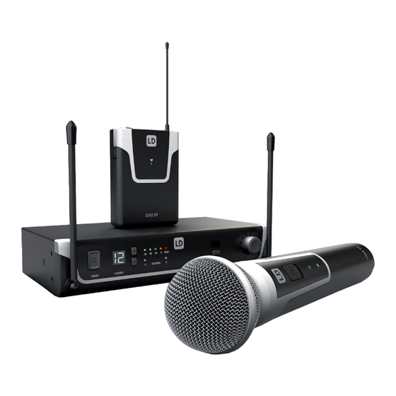
    Pilotton Die Pilotton-Einrichtung schützt eine drahtlose Mikrofonanlage vor Einstreuungen unerwünschter Signale, beispielsweise die von anderen Funkanla- gen. Der Sender fügt dem eigentlich zu übertragenden Signal ein zweites, unhörbares Signal, den Pilotton, hinzu. Der Empfänger identifiziert diesen als den übereinstimmenden Pilotton und gibt das dazugehörige Signal frei. Signale ohne übereinstimmenden Pilotton bleiben stumm geschaltet. Lieferumfang LDU30xHHD: Empfänger plus Handsender mit dynamischer Kapsel (cardioid), Netzteil, 2x AA Batterien, Audiokabel, Anleitung LDU30xBPH: Empfänger plus Taschensender und Headset (schwarz), Netzteil, 2x AA Batterien, Audiokabel, Anleitung...
  • Seite 19 Um den Sender mit dem im Empfänger eingestellten Funkkanal zu synchronisieren, bringen Sie die Infrarot-Schnittstelle des Senders in direkten Sicht- kontakt zur Infrarot-Schnittstelle des Empfängers und schalten Sender und Empfänger ein (Distanz ca. 10cm, IR-Schnittstelle des Handsenders unterhalb der Status-LED, IR-Schnittstelle des Taschensenders auf der Vorderseite). Drücken Sie nun auf den ASC-Taster, um den Synchronisierungsvorgang zu starten, eine rote Anzeige-LED im Fenster der IR-Schnittstelle leuchtet während des Vorgangs.
  • Seite 20: Batteriefachabdeckung

    HANDSENDER MIKROFONKOPF Der Mikrofonkopf ist austauschbar, der Handsender ist kompatibel mit den optional erhältlichen Mikrofonköpfen der LD U500® Serie. ON / OFF Ein- bzw. Ausschalter. Bringen Sie den Schalter in Position ON, um den Handsender einzuschalten, in Position OFF, um ihn auszuschalten. STATUS-LED Ist der Ladestatus der eingelegten Batterien ausreichend, leuchtet die LED bei eingeschaltetem Handsender grün.
  • Seite 21 TASCHENSENDER ANTENNE Antenne des Taschensenders. Für einen optimalen Empfang nicht verdecken oder knicken. IR-SCHNITTSTELLE Infrarot-Schnittstelle zum Synchronisieren des Funkkanals von Empfänger und Sender. INPUT 3-polige Mini-XLR-Buchse zum Anschließen eines Headsets oder Lavalier- bzw. Instrumentenmikrofons sowie eines Gitarrenkabels. ON / STANDBY / OFF Schalter zum Ein- bzw.
  • Seite 22: Belegung Mini-Xlr-Anschluss (Taschensender)

    BATTERIEFACH Zum Austauschen der Batterien öffnen Sie das Batteriefach des Taschensenders, indem Sie gleichzeitig auf beide Markierungen an den Seiten des Bat- teriefachdeckels drücken und ihn nach vorne klappen. Entnehmen Sie die verbrauchten Batterien und setzen frische Batterien (2x Typ AA / LR6, Alkaline) gemäß...
  • Seite 23: Fehlersuche

    FEHLERSUCHE PROBLEM ANZEIGE LÖSUNG Kein Audiosignal oder zu Empfänger: Empfang wird weder auf Antenne A noch Überprüfen Sie, ob der Sender eingeschaltet ist. niedriger Pegel B angezeigt. Überprüfen Sie die Batterien des Senders. Empfänger: Displaybeleuchtung ist abgeschaltet Überprüfen Sie die Stromversorgung des Empfängers und ob der Empfänger eingeschaltet ist.
  • Seite 24: Technische Daten

    LDU500RK2 - 19“ Rackeinbau-Kit für den Einbau zweier Einzelempfänger (2 Rackwinkel, 2 Verbindungselemente und 1 Satz Schrauben inklusive). Montage 1. Verbindungselemente anschrauben (Empfänger A rechte Seite, Empfänger B linke Seite). 2. Beide Empfänger zusammenführen und verschrauben. 3. Rackwinkel anschrauben (Empfänger A linke Seite, Empfänger B rechte Seite). TECHNISCHE DATEN EMPFÄNGER Artikelbezeichnung:...
  • Seite 25 Klirrfaktor (THD, <0,3% <0,3% <0,3% <0,3% <0,3% System): Rauschabstand >104 dB >104 dB >104 dB >104 dB >104 dB (System): Symmetrischer Ausgang: Unsymmetrischer 6,3-mm-Klinken- 6,3-mm-Klinken- 6,3-mm-Klinken- 6,3-mm-Klinken- 6,3-mm-Klinken- Ausgang: buchse buchse buchse buchse buchse Audio-Ausgangspe- +10 dBu +10 dBu +10 dBu +10 dBu +10 dBu gel (symmetrisch):...
  • Seite 26 Kanäle: Mikrofontyp: dynamisch dynamisch dynamisch dynamisch dynamisch Richtcharakteristik: Niere Niere Niere Niere Niere Frequenzgang: 55 – 16.000 Hz 55 – 16.000 Hz 55 – 16.000 Hz 55 – 16,000 Hz 55 – 16.000 Hz Sendeleistung: 10 mW (PEP) 10 mW (PEP) 10 mW (PEP) 10 mW (PEP) 10 mW (PEP)
  • Seite 27: Mikrofone Für Taschensender

    Bedienelemente: ON (An) / STANDBY ON (An) / STANDBY ON (An) / STANDBY ON (An) / STANDBY ON (An) / STANDBY / OFF (Aus), MIC / / OFF (Aus), MIC / / OFF (Aus), MIC / / OFF (Aus), MIC / / OFF (Aus), MIC / 0 / -10 0 / -10...
  • Seite 28: Herstellererklärungen

    HERSTELLERERKLÄRUNGEN HERSTELLERGARANTIE & HAFTUNGSBESCHRÄNKUNG Unsere aktuellen Garantiebedingungen und Haftungsbeschränkung finden Sie unter: https://cdn-shop.adamhall.com/media/pdf/MANUFACTU- RERS-DECLARATIONS_LD_SYSTEMS.pdf. Im Service Fall wenden Sie sich bitte an Adam Hall GmbH, Adam-Hall-Str. 1, 61267 Neu Anspach / E-Mail Info@adamhall.com / +49 (0)6081 / 9419-0. KORREKTE ENTSORGUNG DIESES PRODUKTS (Gültig in der Europäischen Union und anderen europäischen Ländern mit Mülltrennung) Dieses Symbol auf dem Produkt oder dazugehörigen Do- kumenten weist darauf hin, dass das Gerät am Ende der Produktlebenszeit nicht zusammen mit dem normalen Hausmüll entsorgt werden darf, um Umwelt- oder Personenschäden durch unkontrollierte Abfallentsorgung zu vermeiden.
  • Seite 29: Francais

    Cet appareil a été développé et fabriqué en appliquant des exigences de qualité très élevées : il garantit des années de fonctionnement sans problème. Grâce à de nombreuses années d‘expérience, LD Systems est un nom connu dans le domaine des produits audio haut de gamme. Veuillez lire attenti- vement ce Manuel Utilisateur : vous apprendrez rapidement à...
  • Seite 30: Introduction

    ATTENTION : Ne démontez jamais le couvercle de l‘appareil, vous risquez de recevoir un choc électrique. L‘appareil ne renferme aucune pièce ni composant réparable ou remplaçable par l‘utilisateur. Ne confiez l‘entreti- en et la réparation qu‘à un personnel qualifié. Le pictogramme en forme de triangle équilatéral contenant un éclair terminé d‘une flèche avertit l‘utilisateur de la présence d‘une tension dangereuse à...
  • Seite 31: D'affichage

    Signal pilote La fonction de signal pilote protège le système de micro sans fil des interférences occasionnées par des signaux indésirables, provenant par exemple d’autres équipements sans fil. L’émetteur superpose au signal qu’il transmet un signal inaudible, le signal pilote. Le récepteur identifie ce dernier comme signal pilote concordant et restitue le signal correspondant.
  • Seite 32 Afin de synchroniser l’émetteur avec le canal radio configuré sur le récepteur, dirigez l’interface infrarouge de l’émetteur en contact visuel direct vers l’interface infrarouge du récepteur, puis mettez en marche l’émetteur et le récepteur (distance d’environ 10 cm, interface infrarouge de l’émetteur à...
  • Seite 33: Compartiment À Piles

    ÉMETTEUR À MAIN TÊTE DE MICRO La tête de micro est interchangeable ; l’émetteur à main est compatible avec les têtes de micro de la série LD U500®, disponibles en option. ON / OFF Interrupteur marche/arrêt. Poussez l’interrupteur en position ON pour mettre en marche l’émetteur à main, en position OFF pour l’arrêter. LED D’ÉTAT Si le niveau de charge des piles insérées est suffisant, la LED s’allume en vert lorsque l’émetteur à...
  • Seite 34 ÉMETTEUR DE POCHE ANTENNE Antenne de l’émetteur de poche. Pour une réception optimale, ne pas la couvrir ou la plier. INTERFACE INFRAROUGE Interface infrarouge pour la synchronisation du canal radio du récepteur et de l’émetteur. INPUT (ENTRÉE) Connecteur mini-XLR à 3 broches pour raccorder un micro serre-tête, un micro cravate, un micro d’instrument ou un câble de guitare. ON / STANDBY / OFF Interrupteur pour mise en marche et arrêt de l’émetteur de poche (ON = émetteur en marche, OFF = émetteur à...
  • Seite 35: (Émetteur De Poche)

    COMPARTIMENT À PILES Pour changer les piles, ouvrez le compartiment à piles de l’émetteur de poche en appuyant simultanément sur les deux marquages apparaissant sur les côtés du couvercle du compartiment à piles avant de l’incliner vers l’avant. Retirez les piles déchargées et insérez les nouvelles piles (2 piles AA, LR6, alcalines) conformément aux schémas figurant dans le compartiment à...
  • Seite 36: Diagnostic Des Pannes

    DIAGNOSTIC DES PANNES PROBLÈME AFFICHAGE SOLUTION Pas de signal audio ou Récepteur : La réception ne s’affiche pas sur l’an- Vérifiez si l’émetteur est en marche. niveau trop faible tenne A ni B. Contrôlez les piles de l’émetteur. Récepteur : L’éclairage de l’écran est coupé. Contrôlez l’alimentation électrique du récepteur et vérifiez si le récepteur est en marche.
  • Seite 37: Caractéristiques Techniques

    LDU500RK2 - Kit d’installation en rack 19“ pour l’installation de deux récepteurs simples (2 équerres de rack, 2 éléments de raccordement et 1 jeu de vis fournis). Montage 1. Visser les éléments de raccordement (récepteur A côté droit, récepteur B côté gauche). 2. Assembler et visser les deux récepteurs. 3.
  • Seite 38 Réduction du bruit : Squelch, niveau fixe Squelch, niveau fixe Squelch, niveau fixe Squelch, niveau fixe Squelch, niveau fixe THD (système) : <0,3 % <0,3 % <0,3 % <0,3 % <0,3 % Rapport signal sur >104 dB >104 dB >104 dB >104 dB >104 dB bruit (système) : Sortie symétrique : Sortie asymétrique : Jack de 6,3 mm Jack de 6,3 mm Jack de 6,3 mm Jack de 6,3 mm...
  • Seite 39 Type de micro : Dynamique Dynamique Dynamique Dynamique Dynamique Courbe de direc- Cardioïde Cardioïde Cardioïde Cardioïde Cardioïde tivité : Réponse en 55 - 16 000 Hz 55 - 16 000 Hz 55 - 16 000 Hz 55 - 16 000 Hz 55 - 16 000 Hz fréquence : Puissance de sortie 10 mW PEP 10 mW PEP 10 mW PEP 10 mW PEP...
  • Seite 40: Alimentation Électrique

    Réponse en 25 - 16 000 Hz 25 - 16 000 Hz 25 - 16 000 Hz 25 - 16 000 Hz 25 - 16 000 Hz fréquence : Puissance de sortie 10 mW PEP 10 mW PEP 10 mW PEP 10 mW PEP 10 mW PEP RF : Gain d’antenne : 0,5 dBi 0,5 dBi 0,5 dBi 0,5 dBi 0,5 dBi Dispositifs de...
  • Seite 41: Déclarations Du Fabricant

    CÂBLE DE GUITARE POUR ÉMETTEUR CEINTURE Référence de l’article : LDWS100GC Connecteur 1 : Mini-XLR à 3 broches Connecteur 2 : Jack de 6,3 mm Longueur du câble : 1,5 m DECLARATIONS GARANTIE FABRICANT & LIMITATION DE RESPONSABILITÉ Nos conditions actuelles de garantie et de limitation de responsabilité sont disponibles à l‘adresse suivante : https://cdn-shop.adamhall.com/media/ pdf/MANUFACTURERS-DECLARATIONS_LD_SYSTEMS.pdf.
  • Seite 42: Español

    Los productos de LD-Systems se caracterizan por su gran calidad, avalada por el prestigio de la marca y una dilatada experiencia como fabri- cante. Lea atentamente este manual de usuario para poder aprovechar rápidamente toda la funcionalidad de su nuevo producto de LD Systems.
  • Seite 43: Introducción

    ATENCIÓN: Para evitar el riesgo de descarga eléctrica, no retire la tapa. El equipo no contiene elementos que el usuario pueda reparar o sustituir. Para cualquier tarea de mantenimiento o reparación, acuda a un técnico cualificado. El símbolo de rayo dentro de un triángulo equilátero advierte al usuario de la presencia de tensiones peligrosas sin aislamiento dentro del equipo que pueden causar una descarga eléctrica.
  • Seite 44: De Visualización

    Tono piloto El ajuste del tono piloto protege un sistema de micrófono inalámbrico frente a las interferencias de señales no deseadas, por ejemplo: las señales de otros sistemas inalámbricos. El transmisor añade a la señal que se debe transmitir realmente una segunda señal inaudible, llamada tono piloto. El receptor identifica esta señal como el tono piloto coincidente y permite aceptar la señal correspondiente.
  • Seite 45 INTERFAZ DE INFRARROJOS Interfaz de infrarrojos para sincronizar el canal de radio del receptor con el del transmisor. Para sincronizar el transmisor con el canal de radio ajustado en el receptor, oriente la interfaz de infrarrojos del transmisor estableciendo un contacto visual directo con la interfaz de infrarrojos del receptor y encienda el transmisor y el receptor (una distancia de aprox.
  • Seite 46 CABEZA DE MICRÓFONO La cabeza de micrófono es intercambiable, el transmisor portátil es compatible con las cabezas de micrófono disponibles opcionalmente de la serie U500® de LD Systems. ON / OFF Interruptor de encendido/apagado. Ponga el interruptor en la posición ON para encender el transmisor portátil; póngalo en la posición OFF para apagarlo.
  • Seite 47 TRANSMISOR DE PETACA ANTENA Antena del transmisor de petaca. Para asegurar una recepción óptima, evite cubrirla o doblarla. INTERFAZ DE INFRARROJOS Interfaz de infrarrojos para sincronizar el canal de radio del receptor y el del transmisor. ENTRADA Toma Mini XLR de 3 pines para conectar un micrófono de diadema o un micrófono Lavalier o un micrófono de instrumento, así como un cable para guitarra.
  • Seite 48: Asignación De Pines Para Conexión Mini Xlr (Transmisor De Petaca)

    COMPARTIMENTO DE PILAS Para cambiar las pilas, abra el compartimento de pilas del transmisor de petaca, oprimiendo al mismo tiempo ambas marcas en los laterales de la tapa del compartimento de pilas y sáquela hacia delante. Extraiga las pilas agotadas y sustitúyalas por pilas nuevas (2 pilas tipo AA, LR6, alcalinas) siguiendo las ilustraciones en el compartimento de pilas.
  • Seite 49: Búsqueda De Errores

    BÚSQUEDA DE ERRORES PROBLEMA INDICACIÓN SOLUCIÓN No hay señal de audio o el Receptor: No se indica recepción en la antena A ni Compruebe que el transmisor está encendido. nivel es demasiado bajo en la B. Revise las pilas del transmisor. Receptor: La iluminación de la pantalla está...
  • Seite 50: Datos Técnicos

    LDU500RK2 - Kit de montaje en bastidor de 19" para la integración de dos receptores individuales (2 ángulos para montaje en bastidor, 2 elementos de unión y 1 juego de tornillos incluidos). Montaje 1. Atornillar los elementos de unión (receptor A en el lado derecho; receptor B en el lado izquierdo). 2.
  • Seite 51 Reducción de ruido: silenciación, nivel silenciación, nivel silenciación, nivel silenciación, nivel silenciación, nivel fijo fijo fijo fijo fijo THD (sistema): <0,3 % <0,3 % <0,3 % <0,3 % <0,3 % Relación señal/ruido >104 dB >104 dB >104 dB >104 dB >104 dB (sistema): Salida balanceada: Salida no balancea- jack de 6,3 mm jack de 6,3 mm jack de 6,3 mm jack de 6,3 mm...
  • Seite 52 Tipo de micrófono: dinámico dinámico dinámico dinámico dinámico Patrón polar: cardioide cardioide cardioide cardioide cardioide Respuesta en 55 - 16.000 Hz 55 - 16.000 Hz 55 - 16.000 Hz 55 - 16.000 Hz 55 - 16.000 Hz frecuencia: Rango de salida RF: 10 mW PEP 10 mW PEP 10 mW PEP...
  • Seite 53 Respuesta en 25 - 16.000 Hz 25 - 16.000 Hz 25 - 16.000 Hz 25 - 16.000 Hz 25 - 16.000 Hz frecuencia: Rango de salida RF: 10 mW PEP 10 mW PEP 10 mW PEP 10 mW PEP 10 mW PEP Ganancia de antena: 0,5 dBi 0,5 dBi 0,5 dBi...
  • Seite 54: Declaraciones Del Fabricante

    CABLE PARA GUITARRA PARA TRANSMISOR DE PETACA Número de artículo: LDWS100GC Conector 1: Mini XLR de 3 pines Conector 2: jack de 6,3 mm Longitud del cable: 1,5 m DECLARACIÓN DEL FABRICANTE GARANTÍA DEL FABRICANTE Y LIMITACIÓN DE RESPONSABILIDAD Consulte nuestras condiciones de garantía y limitaciones de responsabilidad en: https://cdn-shop.adamhall.com/media/pdf/MANUFACTURERS-DECLARA- TIONS_LD_SYSTEMS.pdf.
  • Seite 55: Polski

    Firma LD Systems gwarantuje to swoją marką i wieloletnim doświadczeniem w wytwarzaniu wysokiej jakości produktów audio. Proszę starannie przeczytać niniejszą instrukcję obsługi, aby móc jak najszybciej zacząć użytkować ten produkt marki LD Systems. Dalsze informacje na temat firmy LD SYSTEMS dostępne są na naszej stronie internetowej WWW.LD-SYSTEMS.COM ŚRODKI OSTROŻNOŚCI...
  • Seite 56: Wprowadzenie

    UWAGA: Nigdy nie zdejmować pokrywy, gdyż grozi to porażeniem prądem. We wnętrzu urządzenia nie ma żadnych części, które mogłyby zostać naprawione bądź poddane czynnościom konserwacyjnym przez użytkownika. Czynności konserwacyjne i naprawy może przeprowadzać wyłącznie wykwalifikowany personel serwisowy. Trójkąt równoboczny z symbolem błyskawicy sygnalizuje nieizolowane, niebezpieczne napięcie we wnętrzu urządzenia, które może spowodować...
  • Seite 57: Przyłącza, Elementy Obsługi I Wskaźniki

    Uwaga! W niektórych krajach stosowanie bezprzewodowego systemu mikrofonowego może wymagać posiadania licencji. Szczegółowe informacje otrzymasz we właściwym urzędzie swojego kraju. Sygnał pilotujący Sygnał pilotujący chroni bezprzewodowy system mikrofonowy przed zakłóceniami sygnału, powodowanymi np. przez inne systemy bezprzewodowe. Nadajnik dodaje do sygnału właściwego, który przekazuje, niesłyszalny sygnał pilotujący. Odbiornik rozpoznaje sygnał pilotujący i przepuszcza zgodny z nim sygnał...
  • Seite 58 Aby zsynchronizować nadajnik z kanałem radiowym ustawionym w odbiorniku, skieruj interfejs podczerwieni nadajnika bezpośrednio na interfejs podczerwieni odbiornika, a następnie włącz nadajnik i odbiornik (odległość ok. 10 cm, interfejs podczerwieni nadajnika ręcznego znajduje się pod diodą stanu baterii, interfejs podczerwieni nadajnika kieszonkowego – na przodzie urządzenia). Naciśnij przycisk ASC, aby rozpocząć synchronizację. W trakcie procesu synchronizacji w okienku interfejsu podczerwieni świeci czerwona dioda LED.
  • Seite 59 NADAJNIK RĘCZNY KAPSUŁA MIKROFONOWA Wymienna kapsuła mikrofonowa; nadajnik ręczny jest kompatybilny z dostępnymi jako opcja kapsułami z serii LD U500®. ON / OFF Włącznik/ wyłącznik. Ustaw przełącznik w pozycji ON, aby włączyć nadajnik ręczny, w pozycji OFF – aby go wyłączyć. DIODA STANU BATERII Jeśli baterie w urządzeniu są...
  • Seite 60 NADAJNIK KIESZONKOWY ANTENA Antena nadajnika kieszonkowego. Dla zapewnienia optymalnego odbioru nie zakrywaj ani nie zginaj anteny. INTERFEJS PODCZERWIENI Interfejs podczerwieni, umożliwiający synchronizację kanału odbiornika i nadajnika. INPUT 3-pinowe gniazdo mini XLR do podłączenia słuchawek, mikrofonu przypinanego/ instrumentalnego lub kabla gitarowego. ON / STANDBY / OFF Włącznik/ wyłącznik nadajnika kieszonkowego (ON = nadajnik jest włączony, OFF = nadajnik jest wyłączony).
  • Seite 61: Schemat Złącza Mini Xlr (Nadajnik Kieszonkowy)

    KOMORA NA BATERIE Aby wymienić baterie w nadajniku kieszonkowym, naciśnij jednocześnie oba oznaczone miejsca na krawędziach pokrywy baterii i przesuń pokrywę do przodu. Wyjmij zużyte baterie i włóż świeże (2 x typ AA / LR6, alkaliczne) zgodnie z oznaczeniami w komorze na baterie. Ponownie przyłóż pokrywę do obudowy, aby się...
  • Seite 62: Znajdowanie Błędu

    ZNAJDOWANIE BŁĘDU PROBLEM KOMUNIKAT ROZWIĄZANIE Brak sygnału audio lub zbyt Odbiornik: Diody nie pokazują sygnału ani na antenie A, Sprawdź, czy nadajnik jest włączony. niski poziom sygnału ani na antenie B. Sprawdź baterie w nadajniku. Odbiornik: Oświetlenie wyświetlacza jest wyłączone Sprawdź, czy odbiornik jest podłączony do zasilania i czy jest włączony.
  • Seite 63: Dane Techniczne

    LDU500RK2 - ZESTAW DO ZAMOCOWANIA DWÓCH ODBIORNIKÓW W SZAFIE RACK 19” (W TYM 2 UCHWYTY MOCUJĄCE, 2 ELEMENTY ŁĄCZĄCE I 1 ZESTAW ŚRUB). MONTAŻ 1. PRZYKRĘĆ ŚRUBAMI ELEMENTY ŁĄCZĄCE (W ODBIORNIKU A PO PRAWEJ STRONIE, W ODBIORNIKU B PO LEWEJ STRONIE) 2.
  • Seite 64 Współczynnik <0.3% <0.3% <0.3% <0.3% <0.3% odkształcenia harmonicznego (THD, system): Stosunek sygnału do >104 dB >104 dB >104 dB >104 dB >104 dB szumu (system): Wyjście symetryczne: Wyjście Gniazdo jack 6,3 mm Gniazdo jack 6,3 mm Gniazdo jack 6,3 mm Gniazdo jack 6,3 mm Gniazdo jack 6,3 mm niesymetryczne:...
  • Seite 65 Kanały: Typ mikrofonu: dynamiczny dynamiczny dynamiczny dynamiczny dynamiczny Charakterystyka kardioidalna kardioidalna kardioidalna kardioidalna kardioidalna kierunkowa: Charakterystyka 55 – 16 000 Hz 55 – 16 000 Hz 55 – 16 000 Hz 55 – 16 000 Hz 55 – 16 000 Hz częstotliwościowa: Moc transmisji: 10 mW (PEP) 10 mW (PEP) 10 mW (PEP) 10 mW (PEP)
  • Seite 66 Moc transmisji: 10 mW (PEP) 10 mW (PEP) 10 mW (PEP) 10 mW (PEP) 10 mW (PEP) Zysk anteny: 0,5 dBi 0,5 dBi 0,5 dBi 0,5 dBi 0,5 dBi Elementy obsługi: ON (włączone) / ON (włączone) / ON (włączone) / ON (włączone) / ON (włączone) / STANDBY / OFF...
  • Seite 67: Deklaracje Producenta

    KABEL GITAROWY DO NADAJNIKA KIESZONKOWEGO Nazwa artykułu: LDWS100GC Wtyk śrubowy 1: 3-stykowe gniazdo mini-XLR Wtyk śrubowy 2: Gniazdo jack 6,3 mm Długość kabla: 1,5 m DEKLARACJE PRODUCENTA GWARANCJA PRODUCENTA I OGRANICZENIE ODPOWIEDZIALNOŚCI Nasze aktualne warunki gwarancji i informacje dotyczące ograniczenia odpowiedzialności znajdą Państwo na stronie: https://cdn-shop.adamhall. com/media/pdf/MANUFACTURERS-DECLARATIONS_LD_SYSTEMS.pdf.
  • Seite 68: Italiano

    Quest‘apparecchio è stato sviluppato e prodotto secondo elevati standard qualitativi che garantiscono un funzionamento regolare per molti anni. Per questo motivo LD Systems, con il suo nome e la pluriennale esperienza, rappresenta un‘azienda produttrice di prodotti audio di qualità. Leggete attentamente questo manuale d‘uso per utilizzare al meglio il vostro nuovo prodotto LD Systems.
  • Seite 69: Introduzione

    ATTENZIONE: non togliere mai il coperchio di protezione perché sussiste il pericolo di scosse elettriche. L‘interno del dispositivo non contiene parti che possono essere riparate o sottoposte a manutenzione da parte dell‘utente. Per gli interventi di manutenzione e di riparazione rivolgersi esclusivamente a personale qualificato.
  • Seite 70: Connettori, Elementi Di Comando E Di Visualizzazione

    Tono pilota La configurazione del tono pilota protegge l’impianto del microfono senza fili dall’interferenza di segnali indesiderati, ad esempio di altri impianti radio. Al segnale da inviare, il trasmettitore aggiunge un secondo segnale impercettibile all’orecchio umano, il tono pilota. Il ricevitore lo identifica come tono pilota e libera il segnale corrispondente.
  • Seite 71 Per sincronizzare il trasmettitore con il canale radio impostato sul ricevitore, orientare l’interfaccia a infrarossi del trasmettitore direttamente verso quella del ricevitore e accendere trasmettitore e ricevitore (distanza ca. 10 cm, interfaccia a infrarossi del trasmettitore manuale sotto al LED di stato, interfaccia a infrarossi del trasmettitore tascabile rivolta verso il pannello frontale).
  • Seite 72 TRASMETTITORE MANUALE TESTA PER MICROFONO La testa per microfono è sostituibile, il trasmettitore manuale è compatibile con le teste per microfoni della serie LD U500®. ON / OFF Interruttore di accensione/spegnimento. Posizionare l'interruttore su ON per accendere il trasmettitore manuale, su OFF per spegnerlo. LED di stato Se le batterie inserite sono sufficientemente cariche, quando il trasmettitore tascabile è...
  • Seite 73 TRASMETTITORE TASCABILE ANTENNA Antenna del trasmettitore tascabile. Per una ricezione ottimale, non coprire o piegare. INTERFACCIA IR Interfaccia infrarossi per sincronizzare il canale radio da ricevitore e trasmettitore manuale. INPUT Presa mini-XLR a 3 poli per il collegamento di un microfono ad archetto o di un microfono Lavalier o di un microfono per strumenti e di un cavo per chitarra.
  • Seite 74: (Trasmettitore Tascabile)

    SCOMPARTO BATTERIE Per la sostituzione delle batterie aprire il relativo scomparto del trasmettitore tascabile premendo contemporaneamente sulle due marcature laterali del coperchio e sollevare in avanti. Togliere le batterie scariche e sostituirle con batterie nuove (2 del tipo AA, LR6, alcaline) osservando le immagini nello scomparto batterie.
  • Seite 75: Ricerca Errori

    RICERCA ERRORI PROBLEMA DISPLAY SOLUZIONE Assenza di segnale audio o Ricevitore: la ricezione non viene visualizzata sull'an- Verificare se il trasmettitore è acceso. livello troppo basso tenna A né B. Controllare le batterie del trasmettitore. Ricevitore: illuminazione display spenta. Controllare l'alimentazione del ricevitore e che il ricevitore sia acceso.
  • Seite 76: Dati Tecnici

    LDU500RK2 - Kit di installazione a rack 19" per l'installazione di due ricevitori singoli (2 angolari rack, 2 elementi di raccordo e 1 set di viti in dotazione). Montaggio 1. Avvitare gli elementi di raccordo (ricevitore A a destra, ricevitore B a sinistra). 2.
  • Seite 77 Soppressione del Squelch (valore Squelch (valore Squelch (valore Squelch (valore Squelch (valore rumore: Squelch fisso) Squelch fisso) Squelch fisso) Squelch fisso) Squelch fisso) Fattore di <0,3% <0,3% <0,3% <0,3% <0,3% distorsione armoni- ca (THD, sistema): Rapporto segnale/ >104 dB >104 dB >104 dB >104 dB >104 dB...
  • Seite 78 Canali: Tipo di microfono: dinamico dinamico dinamico dinamico dinamico Caratteristica cardioide cardioide cardioide cardioide cardioide direzionale: Risposta in fre- 55 - 16.000 Hz 55 - 16.000 Hz 55 - 16.000 Hz 55 - 16,000 Hz 55 - 16.000 Hz quenza: Potenza di trasmis- 10 mW (PEP) 10 mW (PEP)
  • Seite 79 Risposta in fre- 25 - 16.000 Hz 25 - 16.000 Hz 25 - 16.000 Hz 25 - 16.000 Hz 25 - 16.000 Hz quenza: Potenza di trasmis- 10 mW (PEP) 10 mW (PEP) 10 mW (PEP) 10 mW (PEP) 10 mW (PEP) sione: Guadagno dell’an- 0,5 dBi...
  • Seite 80: Dichiarazioni Del Produttore

    CAVO PER CHITARRA PER TRASMETTITORE TASCABILE Denominazione articolo: LDWS100GC Connettore a innesto 1: mini XLR a 3 poli Connettore a innesto 2: jack da 6,3 mm Lunghezza cavo: 1,5 m DICHIARAZIONI DEL PRODUTTORE GARANZIA DEL PRODUTTORE E LIMITAZIONE DI RESPONSABILITÀ Le nostre attuali condizioni di garanzia e la limitazione di responsabilità...
  • Seite 84 LD-SYSTEMS.COM Adam Hall GmbH | Adam-Hall-Str. 1 | 61267 Neu-Anspach | Germany Phone: +49 6081 9419-0 | adamhall.com REV: 04...

Diese Anleitung auch für:

U306U305U308U304

Inhaltsverzeichnis