Herunterladen Inhalt Inhalt Diese Seite drucken
LD Systems U500 Serie Bedienungsanleitung
Vorschau ausblenden Andere Handbücher für U500 Serie:
Inhaltsverzeichnis

Werbung

Verfügbare Sprachen
  • DE

Verfügbare Sprachen

  • DEUTSCH, seite 18
USER´S MANUAL
BEDIENUNGSANLEITUNG
MANUEL D´UTILISATION
MANUAL DE USUARIO
INSTRUKCJA OBSŁUGI
MANUALE D´USO
U500® SERIES
TRUE DIVERSITY WIRELESS SYSTEM

Werbung

Inhaltsverzeichnis

Fehlerbehebung

loading

Inhaltszusammenfassung für LD Systems U500 Serie

  • Seite 1 USER´S MANUAL BEDIENUNGSANLEITUNG MANUEL D´UTILISATION MANUAL DE USUARIO INSTRUKCJA OBSŁUGI MANUALE D´USO U500® SERIES TRUE DIVERSITY WIRELESS SYSTEM...
  • Seite 2: Inhaltsverzeichnis

    CONTENTS / INHALTSVERZEICHNIS / CONTENU / CONTENIDO / TREŚĆ / CONTENUTO ENGLISH ESPAÑOL PREVENTIVE MEASURES MEDIDAS DE SEGURIDAD INTRODUCTION INTRODUCCIÓN SCOPE OF DELIVERY ELEMENTOS SUMINISTRADOS CONNECTIONS, CONTROLS AND INDICATORS CONEXIONES, CONTROLES E INDICADORES BELTPACK MINI-XLR PIN ASSIGNMENT PINEADO DEL MINI-XLR DE LA PETACAA RECEIVER OPERATION USO DEL RECEPTOR TRANSMITTER OPERATION...
  • Seite 3: Preventive Measures

    You‘ve made the right choice! We have designed this product to operate reliably over many years. LD Systems stands for this with its name and many years of experience as a manufacturer of high-quality audio products. Please read this User‘s Manual carefully, so that you can begin making optimum use of your LD Systems product quickly.
  • Seite 4: Introduction

    CAUTION: To reduce the risk of electric shock, do not remove cover (or back). There are no user serviceable parts inside. Maintenance and repairs should be exclusively carried out by qualified service personnel. The warning triangle with lightning symbol indicates dangerous uninsulated voltage inside the unit, which may cause an electrical shock. The warning triangle with exclamation mark indicates important operating and maintenance instructions.
  • Seite 5: Connections, Controls And Indicators

    LDU5xxHHC2: Dual receiver plus 2 x hand-held transmitter and condenser capsule (cardioid), power supply, 2 x BNC antennas, audio cable, 4 x AA batteries, carrying case, rack kit, instructions LDU5xxHHD2: Dual receiver plus 2 x hand-held transmitter and dynamic capsule (cardioid), power supply, 2 x BNC antennas, audio cable, 4 x AA batteries, carrying case, rack kit, instructions LDU5xxBPH2: Dual receiver plus 2 x hand-held transmitter and headset (black), power supply, 2 x BNC antennas, audio cable, 4 x AA batteries, carrying case, rack kit, instructions...
  • Seite 6 Screw holes for 19” rack mounting. DC SOCKET Low-voltage socket for the power supply of the device. (Single receiver: DC 12V Plus internal/ 500 mA, Dual receiver: DC 12 V Plus internal/ 1000 mA). Please only use the power adapter included. ANTENNA A/B BNC antenna connector A and B.
  • Seite 7: Belt Pack Transmitter

    HANDHELD TRANSMITTER 20 19 BELT PACK TRANSMITTER ON / OFF On / Off switch. Set the switch to the ON position to turn the receiver on, and to the OFF position to turn it off. DISPLAY Multi-functional OLED graphics display for displaying the frequency group and channel, the username and battery status. Also indicates the menu items in order to adjust transmitter settings as desired.
  • Seite 8: Receiver Operation

    MINI-XLR ava3 Condenser with internal pull up resistor. MINI-XLR 2,2k Condenser without internal pull up resistor. RECEIVER OPERATION When operating the wireless transmission system, be sure to place the receiver in the line of sight of the transmitter. For optimal reception, perform the automatic frequency search after switching on the receiver.
  • Seite 9: Pilot Tone

    GROUP Menu item to adjust the frequency group. The LD U500 wireless system has 8 frequency groups, which can be selected as desired. Press the pressure rotary encoder (MENU) to access the Edit menu and select the menu item GROUP by rotating the encoder (light background). Press MENU again and select one of the groups 01 to 08 by rotating the encoder.
  • Seite 10: Panel Lock

    SQUELCH The squelch control prevents unwanted background noise when the transmitter is turned off. In addition, sudden background noises are sup- pressed when the signal transmitted from the transmitter to the receiver is not strong enough (for instance because of excessive distance) Set the squelch control (with the transmitter switched off) to the lowest setting, which still effectively suppresses background noises.
  • Seite 11: Transmitter Operation

    TRANSMITTER OPERATION MAIN DISPLAY After switching on the transmitter, the main screen displays the following information: username, frequency group and channel (GR.xx and CH.xx) and battery status. Remove the battery compartment cover on the transmitter to release the controls SEL and arrow buttons (hand-held transmitter: remove the screwable cover shell by rotating it to the left, belt pack transmitter: pull cover shell by pressing on the markings on the sides of the housing).
  • Seite 12: Battery Replacement

    ATTACHING THE PACK TRANSMITTER Attach the transmitter to a belt or strap as shown below. BATTERY REPLACEMENT Open the battery compartment of the hand-held transmitter by turning the battery compartment cover counter-clockwise and pull it from the housing. Remove the used batteries and insert new batteries (AA, Mignon) as shown on the illustration inside the battery compartment. Replace the battery compartment cover on the housing and close the battery compartment by turning clockwise.
  • Seite 13: Troubleshooting

    TROUBLESHOOTING PROBLEM DISPLAY SOLUTION No audio signal or Receiver: Reception is not displayed on antenna A or B. Verify that the transmitter is turned on. low level Check the batteries in the transmitter. Receiver: Display light is off Check the power supply in the transmitter. Receiver: Reception is not displayed on antenna A or B.
  • Seite 14: Specifications

    MOUNTING Screw the connectors (receiver A right, receiver B left). Place both receivers together and screw into place. Screw the rack brackets (receiver A right, receiver B left). An extensive selection of suitable LD U500 wireless systems and further accessories can be found at www.LD-SYSTEMS.COM SPECIFICATIONS Receiver Model name:...
  • Seite 15 Headphones output: 6.3 mm stereo jack Audio output level (balanced): +10dBu Audio output level +6dBV / 0dBV (Switchable Line / Instrument) (unbalanced): Controls: POWER on/off, MENU push-turn-control, VOL POWER on/off, 2x MENU push-turn-control, 2x Volume control, switch INSTRUMENT/LINE VOL Volume control, 2x switch INSTRUMENT/LINE, headphones volume control Indicators: multifunctional OLED-graphic display,...
  • Seite 16 Channels: 96 (8 x 12) Groups: Input: 3-pin mini-XLR (Low-Z/High-Z) Frequency response: 30 - 16.000 Hz THD: <0.1% @ 1kHz Signal-to-noise ratio: >90 dB RF output power: 2mW, 10mW, 30mW switchable and depending on the RF -Range Antenna Gain: 0.5 dBi Controls: Power on/off, Select, Arrow button Indicators:...
  • Seite 17: Manufacturer´s Declarations

    Guitar cable Model name: LDU500GC Connector 1: 3-pin mini-XLR Connector 2: 6.3 mm jack Length: 0.8 m MANUFACTURER´S DECLARATIONS MANUFACTURER‘S WARRANTY & LIMITATIONS OF LIABILITY You can find our current warranty conditions and limitations of liability at: https://cdn-shop.adamhall.com/media/pdf/MANUFACTURERS-DECLARA- TIONS_LD_SYSTEMS.pdf To request warranty service for a product, please contact Adam Hall GmbH, Adam-Hall-Str. 1, 61267 Neu Anspach / Email: Info@adamhall.com / +49 (0)6081 / 9419-0.
  • Seite 18: Deutsch

    Dieses Gerät wurde unter hohen Qualitätsanforderungen entwickelt und gefertigt, um viele Jahre einen reibungslosen Betrieb zu gewährleisten. Dafür steht LD Systems mit seinem Namen und der langjährigen Erfahrung als Hersteller hochwertiger Audioprodukte. Bitte lesen Sie diese Bedie- nungsanleitung sorgfältig, damit Sie Ihr neues Produkt von LD Systems schnell optimal einsetzen können.
  • Seite 19: Einführung

    Belastung durch hohe Lautstärken über 90 dB. EINFÜHRUNG Die Funkübertragungssysteme der LD U500 Serie bieten professionelle Leistung und Funktionen einschließlich der automatischen Kanalsuche und der bequemen One-Touch-Infrarot-Synchronisierung für einfache Einrichtung. Mit schaltbarer HF-Leistung, Pilotton-Übertragung und einer Auswahl von dynamischen und Kondensatormikrofonen liefern U500 Systeme hervorragenden Klang mit erweiterter Dynamik.
  • Seite 20: Anschlüsse, Bedien- Und Anzeigeelemente

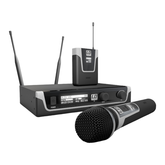
    LDU5xxBPH2: Doppelempfänger plus 2x Taschensender und Headset (schwarz), Netzteil, 2x BNC-Antennen, Audiokabel, 4x AA Batterien, Transportkoffer, Rack-Kit, Anleitung LDU5xxBPHH2: Doppelempfänger plus 2x Taschensender und Headset (hautfarben), Netzteil, 2x BNC-Antennen, Audiokabel, 4x AA Batterien, Transportkoffer, Rack-Kit, Anleitung Eine umfangreiche Auswahl an LD U500 Einzelkomponenten und Zubehör finden Sie auf www.LD-SYSTEMS.COM ANSCHLÜSSE, BEDIEN- UND ANZEIGEELEMENTE EMPFÄNGER POWER...
  • Seite 21 DC BUCHSE Kleinspannungsbuchse für die Spannungsversorgung des Geräts (Einzelempfänger: DC 12V Plus innen, 500mA, Doppelempfänger: DC 12V Plus innen, 1000mA). Verwenden Sie bitte ausschließlich den mitgelieferten Netzadapter. ANTENNE A/B BNC-Antennenanschluß A und B. Für einen optimalen Empfang schließen Sie bitte jeweils eine mitgelieferte Antenne an den Anschlüssen A und B an und richten sie nach oben in „V“...
  • Seite 22 HANDSENDER 20 19 TASCHENSENDER ON / OFF Ein- bzw. Ausschalter. Bringen Sie den Schalter in Position ON, um den Sender einzuschalten, in Position OFF, um ihn auszuschalten. DISPLAY Multifunktionales OLED-Grafikdisplay für die Anzeige von Frequenz-Gruppe und -Kanal, Nutzernamen und Batteriestatus. Zeigt weiterhin die Menü- punkte an, um Sendereinstellungen nach Wunsch vorzunehmen.
  • Seite 23: Belegung Mini-Xlr-Anschluss (Taschensender)

    BELEGUNG MINI-XLR-ANSCHLUSS (TASCHENSENDER) MINI-XLR 6,3 mm jack sleeve Gitarre, Bass und andere hochohmige Signalquellen. MINI-XLR Kondensatormikrofon mit internem Pull-up-Widerstand. MINI-XLR 2,2k Kondensatormikrofon ohne internem Pull-up-Widerstand. BEDIENUNG EMPFÄNGER Achten Sie bei der Inbetriebnahme des drahtlosen Übertragungssystems darauf, den Empfänger in direktem Sichtkontakt mit dem Sender zu posi- tionieren.
  • Seite 24 FREQ AUTO RUN Automatische Frequenzsuche (Frequenz-Scan), um in der aktuellen Umgebung eine interferenzfreie Funkfrequenz zu ermitteln und einen optimalen Empfang zu ermöglichen. Lassen Sie bei dem Vorgang den dazugehörigen Sender aus-, gegebenenfalls weitere Funksysteme aber eingeschaltet. Drücken Sie auf den Drück-Dreh-Geber MENU, um in das Bearbeitungsmenü zu gelangen und wählen dann durch Drehen des Gebers den Menüpunkt FREQ AUTO RUN aus (hell hinterlegt).
  • Seite 25: Pilot Tone

    PILOT TONE Die Pilot-Ton-Einrichtung schützt eine drahtlose Mikrofonanlage vor Einstreuungen unerwünschter Signale, beispielsweise die von anderen Funk- anlagen. Der Sender fügt dem eigentlich zu übertragenden Signal ein zweites, unhörbares Signal, den Pilot-Ton, hinzu. Der Empfänger identifiziert diesen als den übereinstimmenden Pilot-Ton und gibt das dazugehörige Signal frei. Signale ohne Pilot-Ton bleiben stummgeschaltet. Drücken Sie auf den Drück-Dreh-Geber MENU, um in das Bearbeitungsmenü...
  • Seite 26: Bedienung Sender

    BATTERY STATUS Der Batteriestatus des entsprechenden Senders wird im Display angezeigt und stetig aktualisiert. Bei voll geladener Batterie erscheint das Symbol = ca. 70%, = ca. 30%). Sobald das Symbol für „Batterie schwach“ angezeigt wird, wechselt das Display etwa alle 5 Sekunden die Anzeige auf „LOW BATTERY“.
  • Seite 27: Batteriestatus

    BATTERIESTATUS Der Batteriestatus des Senders wird im Display angezeigt und stetig aktualisiert. Bei voll geladener Batterie erscheint das Symbol = ca. 70%, = ca. 30%). Sobald das Symbol für „Batterie schwach“ angezeigt wird, wechselt das Display etwa alle 5 Sekunden die Anzeige auf „LOW BATTERY“.
  • Seite 28: Fehlersuche

    FEHLERSUCHE PROBLEM ANZEIGE LÖSUNG Kein Audiosignal oder Empfänger: Empfang wird weder auf Antenne A noch Überprüfen Sie, ob der Sender eingeschaltet ist. zu niedriger Pegel B angezeigt. Überprüfen Sie die Batterien des Senders. Empfänger: Displaybeleuchtung ist abgeschaltet Überprüfen Sie die Stromversorgung des Empfängers Empfänger: Empfang wird weder auf Antenne A noch Überprüfen, ob Funkfrequenz von Sender und Empfänger B angezeigt.
  • Seite 29: Technische Daten

    MONTAGE Verbindungselemente anschrauben (Empfänger A rechts, Empfänger B links). Beide Empfänger zusammenführen und verschrauben. Rackwinkel anschrauben (Empfänger A links, Empfänger B rechts). Eine umfangreiche Auswahl an LD U500 Funksystemen und weiterem Zubehör finden Sie auf www.LD-SYSTEMS.COM TECHNISCHE DATEN Empfänger Modellbezeichnung: LDU50xR LDU50xR2 Empfängertyp:...
  • Seite 30 Abmessungen (B x H x T): 212 x 44 x 159 mm 484 x 44 x 200 mm Gewicht: 0,95 kg 2,05 kg Zubehör (im Lieferumfang): Netzadapter, 2 x Antennen, Audiokabel Netzadapter, 2 x Antennen, Audiokabel, Rack Kit Features: Automatische Kanalsuche, IR-Frequenzsynchronisation, Pilotton Handsender: Modellbezeichnung: LDU50xMD...
  • Seite 31 Antennengewinn: 0,5 dBi Bedienelemente: Power On/Off, Select, Pfeiltaste Anzeigeelemente: Multifunktionales OLED-Grafikdisplay Stromversorgung: 2 AA-Batterien (Mignon-Zellen) Betriebsdauer: bis zu 10 h (je nach Batterietyp) Temperaturbereich: 5°C … 40°C Relative Luftfeuchte während Betrieb: 20% … 80% (nicht kondensierend) Abmessungen (B x H x T): 65 x 86 x 23 mm Gewicht (ohne Batterien): 0,09 kg...
  • Seite 32: Herstellererklärungen

    HERSTELLERERKLÄRUNGEN HERSTELLERGARANTIE & HAFTUNGSBESCHRÄNKUNG Unsere aktuellen Garantiebedingungen und Haftungsbeschränkung finden Sie unter: https://cdn-shop.adamhall.com/media/pdf/MANUFACTU- RERS-DECLARATIONS_LD_SYSTEMS.pdf. Im Service Fall wenden Sie sich bitte an Adam Hall GmbH, Adam-Hall-Str. 1, 61267 Neu Anspach / E-Mail Info@adamhall.com / +49 (0)6081 / 9419-0. KORREKTE ENTSORGUNG DIESES PRODUKTS (Gültig in der Europäischen Union und anderen europäischen Ländern mit Mülltrennung) Dieses Symbol auf dem Produkt oder dazugehörigen Do- kumenten weist darauf hin, dass das Gerät am Ende der Produktlebenszeit nicht zusammen mit dem normalen Hausmüll entsorgt werden darf, um Umwelt- oder Personenschäden durch unkontrollierte Abfallentsorgung zu vermeiden.
  • Seite 33: Francais

    Cet appareil a été développé et fabriqué en appliquant des exigences de qualité très élevées : il garantit des années de fonctionnement sans problème. Grâce à de nombreuses années d‘expérience, LD Systems est un nom connu dans le domaine des produits audio haut de gamme. Veuillez lire attentivement ce Manuel Utilisateur : vous apprendrez rapidement à...
  • Seite 34: Introduction

    INTRODUCTION Les systèmes HF LD Systems de la Série U500 offrent une puissance et des fonctionnalités professionnelles, parmi lesquelles la recherche automa- tique de canaux et la synchronisation des fréquences en infrarouge, via une touche, ce qui facilité la configuration système. Outre une puissance d’émission HF commutable, une liaison par signal pilote et le choix entre capsules dynamiques ou statiques, les systèmes U500 possèdent un son...
  • Seite 35: Connecteurs, Contrôles Et Indicateurs

    LDU5xxBPW : Récepteur 1 canal, plus émetteur de poche et micro sur pince pour cuivres, bloc secteur, 2 antennes BNC, câble audio, 2 piles AA, mallette de transport, mode d’emploi LDU5xxHHC2 : Récepteur 2 canaux, plus 2 émetteurs à main et capsules statiques (cardioïdes), bloc secteur, 2 antennes BNC, câble audio, 4 piles AA, mallette de transport, kit de montage en rack, mode d’emploi LDU5xxHHD2 : Récepteur 2 canaux, plus 2 émetteurs à...
  • Seite 36 Trous pour fixation en rack 19 pouces. EMBASE DC Cette embase reçoit la tension continue d’alimentation extérieure de l’appareil (récepteur 1 canal : tension continue 12 V, Plus au centre, intensité 500 mA. Récepteur 2 canaux : tension continue 12 V, Plus au centre, intensité 1000 mA. Veuillez n’utiliser que le bloc secteur livré. ANTENNE A/B Embases BNC pour antennes A et B.
  • Seite 37: Brochage Transmetteur Ceinture Mini-Xlr

    ÉMETTEUR DE POCHE ON / OFF Interrupteur marche/arrêt. Placez l’interrupteur en position ON pour allumer l’émetteur, en position OFF pour l’éteindre. DISPLAY Afficheur graphique OLED multifonctions, visualisation du groupe de fréquences et de la fréquence du canal, du nom de l’utilisateur et de l’état des piles.
  • Seite 38: Utilisation Du Récepteur

    MINI-XLR 2,2k Condensateur sans résistance d’excursion interne. UTILISATION DU RÉCEPTEUR Lors de l’utilisation de votre système HF, assurez-vous que l’émetteur se trouve en contact visuel direct avec le récepteur. Après mise sous tension du récepteur, lancez la recherche automatique de fréquences, afin d’obtenir une réception optimale. Pour ce faire, laissez allumés tous les autres émetteurs HF voisins, mais éteignez l’émetteur de votre système HF.
  • Seite 39: Pilot Tone

    CHANNEL Choix d’une fréquence de canal Le système HF LD U500 propose 8 groupes de fréquences contenant 12 canaux chacun, sélectionnables à volonté. Appuyez sur l’encodeur/touche du récepteur (MENU) pour accéder au menu d’utilisation, et sélectionnez, en tournant l’encodeur, l’élément de menu CHANNEL (il passe en surbrillance).
  • Seite 40: Panel Lock

    SQUELCH La fonction Squelch permet d’éviter des bruits parasites indésirables lorsque l’émetteur est éteint. Même principe si le niveau HF reçu devient trop faible (par exemple, à cause d’une distance excessive entre émetteur et récepteur). L’émetteur étant éteint, réglez le niveau de Squelch au minimum : les bruits parasites sont alors audibles en sortie du récepteur.
  • Seite 41: Utilisation De L'émetteur

    UTILISATION DE L’ÉMETTEUR ÉCRAN PRINCIPAL Lors de l’allumage de l’émetteur, apparaît dans l’afficheur l’écran principal, qui rassemble les informations suivantes : Nom de l’utilisateur, groupe de fréquences et canal (GR.xx et CH.xx) , état des piles. Pour accéder aux touches SEL et Flèche de l’émetteur, dégagez le capot du compartiment à...
  • Seite 42: Remplacement Des Piles

    FIXATION DE L’ÉMETTEUR DE POCHE Vous pouvez accrocher l’émetteur à une ceinture ou à une sangle de guitare comme indiqué sur le schéma ci-dessous. REMPLACEMENT DES PILES Pour accéder aux piles de l’émetteur à main, il suffit de dévisser sa partie inférieure, puis de la dégager. Enlevez alors les piles usées, puis placez deux piles alcalines de type AA (LR06, Mignon) conformément aux indications figurant sur le fond du compartiment à...
  • Seite 43: En Cas De Problème

    EN CAS DE PROBLÈME PROBLÈME SYMPTÔME SOLUTION Pas de signal audio, Récepteur : Il est indiqué si la réception s'effectue via Vérifiez si l'émetteur est allumé. ou niveau très faible l'antenne A ou l'antenne B. Vérifiez les piles de l'émetteur. Récepteur : Le rétro-éclairage de l'écran est désactivé. Vérifiez l'alimentation secteur du récepteur.
  • Seite 44: Caractéristiques Techniques

    MONTAJE Visser les éléments de liaison (récepteur A à gauche, récepteur B à droite). Rapprocher et visser ensemble les deux récepteurs. Visser les équerres de mise en rack (récepteur A à gauche, récepteur B à droite). Vous trouverez un large choix de systèmes HF LD U500 et d’accessoires supplémentaires à l’adresse www.LD-SYSTEMS.COM CARACTÉRISTIQUES TECHNIQUES Récepteur Référence :...
  • Seite 45 Niveau de sortie audio (symétrique) +10 dBu Niveau de sortie audio +6 dBV / 0 dBV (commutation Line / Instrument) (asymétrique) Contrôles : Touche POWER on/off, encodeur/touche Touche POWER on/off, 2 x encodeur/touche MENU, MENU, potentiomètre VOL, sélecteur 2 x potentiomètre VOL, 2 x sélecteur INSTRUMENT/ INSTRUMENT/LINE LINE, réglage volume casque Indicateurs :...
  • Seite 46 Émetteur de poche (Bodypack) Référence : LDU50xBP Modulation: Gammes de Fréquences HF : 823 - 832 MHz & 863 - 865 MHz (LDU508), 584 - 607 MHz (LDU505), 655 - 679 MHz (LDU506), 604 - 614 MHz (LDU506UK), 1785 - 1800 MHz (LDU518) Nombre de canaux : 96 (8 x 12) Nombre de Groupes :...
  • Seite 47: Declarations

    Points forts : Convertisseur d'impé- Suspension, contacts or Convertisseur d'impé- Suspension, contacts or dance FET à faible bruit dance FET à faible bruit de fond, suspension de fond, suspension optimisée, contacts or optimisée, contacts or Câble Guitare Référence : LDU500GC Connecteur 1 : Mini-XLR 3 points Connecteur 2 :...
  • Seite 48: Medidas De Seguridad

    Los productos de LD-Systems se caracterizan por su gran calidad, avalada por el prestigio de la marca y una dilatada experiencia como fabri- cante. Lea atentamente este manual de usuario para poder aprovechar rápidamente toda la funcionalidad de su nuevo producto de LD Systems.
  • Seite 49: Introducción

    El símbolo de exclamación dentro de un triángulo equilátero advierte al usuario de la existencia de importantes instrucciones de uso y mantenimiento. ¡Advertencia! Este símbolo indica la presencia de superficies calientes. Durante el funcionamiento, algunas partes de la carcasa pueden llegar a calentarse bastante. Por ello, una vez apagado el equipo, espere al menos 10 minutos antes de manipularlo o transportarlo.
  • Seite 50: Conexiones, Controles E Indicadores

    CONEXIONES, CONTROLES E INDICADORES RÉCEPTEUR POWER Botón de encendido/apagado. Mantenga pulsado durante 2 segundos para encender o apagar el equipo. DISPLAY Pantalla gráfica OLED multifuncional en la que se muestra información como la frecuencia de radio, el nivel de la señal de RF y el nivel de la señal de audio.
  • Seite 51 Orificios de los tornillos para el montaje en rack de 19”. TOMA DE ALIMENTACIÓN DE CONTINUA Toma de alimentación eléctrica del equipo (receptor único: DC 12V con positivo en el contacto central, 500 mA; receptor doble: DC 12V con positivo en el contacto central, 1000 mA). Utilice únicamente el adaptador de corriente suministrado. ANTENNE A/B Tomas BNC de las antenas A y B.
  • Seite 52 MICRÓFONO TRANSMISOR DE MANO 20 19 PETACA TRANSMISORA ON / OFF Interruptor de encendido/apagado. Sitúe el conmutador en la posición ON para encender el transmisor y sitúelo en la posición OFF para apagarlo. DISPLAY Pantalla gráfica OLED multifuncional en la que se muestra el grupo y el canal de la frecuencia sintonizada, el nombre del usuario y el estado de la batería.
  • Seite 53: Pineado Del Mini-Xlr De La Petacaa

    PINEADO DEL MINI-XLR DE LA PETACAA MINI-XLR 6,3 mm jack sleeve Guitarra, bajo y otras fuentes de alta impedancia. MINI-XLR Condensador con resistencia interna. MINI-XLR 2,2k Condensador sin resistencia interna. USO DEL RECEPTOR Al poner en marcha el sistema de transmisión inalámbrica, asegúrese de que haya una línea visual directa entre el receptor y el transmisor. Después de encender el receptor, ejecute la búsqueda automática de frecuencias para conseguir una recepción óptima.
  • Seite 54 FREQ AUTO RUN Realice una búsqueda automática de frecuencias (barrido de frecuencias) para detectar en el entorno actual una frecuencia de radio que no tenga interferencias y poder obtener una recepción óptima. Deje apagado el transmisor correspondiente, aunque puede dejar encendidos los demás sistemas inalámbricos.
  • Seite 55: Pilot Tone

    PILOT TONE El tono piloto protege un sistema de micrófono inalámbrico contra las interferencias de señales no deseadas, como las ocasionadas por otros equi- pos inalámbricos. El transmisor añade a la señal transmitida una segunda señal inaudible, conocida como tono piloto. El receptor detecta esta señal como la del tono piloto e identifica como correcta la señal asociada.
  • Seite 56: Estado De La Batería

    ESTADO DE LA BATERÍA En la pantalla se muestra el estado actual de la batería del transmisor correspondiente. Cuando las pilas están completamente cargadas, se indica con el icono  = 70% aprox.,  = 30% aprox.). Cuando se muestre el icono de nivel de batería bajo , la pantalla cambiará...
  • Seite 57: Sustitución De Las Pilas

    EXIT Para salir del menú de ajustes y volver a la pantalla principal, seleccione la opción EXIT y confirme con el botón de flecha. Al cabo de 10 segundos de inactividad, se volverá automáticamente a la pantalla principal. ESTADO DE LA BATERÍA En la pantalla se muestra el estado actual de la batería del transmisor.
  • Seite 58: Solución De Problemas

    SOLUCIÓN DE PROBLEMAS PROBLEMA INDICACIONES SOLUCIÓN No hay audio o es Receptor: no indica recepción ni por la antena A ni Compruebe que está encendido el transmisor. demasiado bajo por la B. Compruebe las pilas del transmisor. Receptor: la pantalla está apagada. Compruebe la alimentación eléctrica del receptor.
  • Seite 59: Características Técnicas

    MOUNTING Atornillar los elementos de conexión (receptor A a la derecha, receptor B a la izquierda). Se colocan juntos ambos receptores y se atornillan. Atornillar las orejas de rack (receptor A a la izquierda, receptor B a la derecha). En la web www.LD-SYSTEMS.COM encontrará una amplia selección de sistemas inalámbricos y más accesorios de la serie LD U500. CARACTERÍSTICAS TÉCNICAS Receptor Modelo:...
  • Seite 60 Rango de temperatura operativa: 5 °C a 40 °C Humedad relativa operativa: 20% a 80% (sin condensación) Dimensiones (An x Al x F): 212 x 44 x 159 mm 484 x 44 x 200 mm Peso: 0,95 kg 2,05 kg Accesorios incluidos: Adaptador de corriente, 2 antenas, cable de Adaptador de corriente, 2 antenas, cable de...
  • Seite 61 Transmisor de petaca Modelo: LDU50xBP Modulación: 823 - 832 MHz & 863 - 865 MHz (LDU508), 584 - 607 MHz (LDU505), 655 - 679 MHz (LDU506), 604 - 614 MHz Banda de frecuencias: (LDU506UK), 1785 - 1800 MHz (LDU518) Canales: 96 (8 x 12) Grupos: Entrada:...
  • Seite 62: Declaración Del Fabricante

    Conector: Conexión roscada LDU500 Conexión roscada LDU500 Conexión roscada LDU500 Conexión roscada LDU500 Color: Plata mate Plata mate Negro mate Negro mate Características: Adaptador de impe- Elemento antichoque, contac- Adaptador de impedancias Elemento antichoque, contac- dancias FET de bajo tos dorados FET de bajo ruido, elemento tos dorados ruido, elemento anti-...
  • Seite 63: Polski

    Firma LD Systems gwarantuje to swoją marką i wieloletnim doświadczeniem w wytwarzaniu wysokiej jakości produktów audio. Proszę starannie przeczytać niniejszą instrukcję obsługi, aby móc jak najszybciej zacząć użytkować ten produkt marki LD Systems. Dalsze informacje na temat firmy LD SYSTEMS dostępne są na naszej stronie internetowej WWW.LD-SYSTEMS.COM ŚRODKI OSTROŻNOŚCI...
  • Seite 64: Wprowadzenie

    UWAGA: Nigdy nie zdejmować pokrywy, gdyż grozi to porażeniem prądem. We wnętrzu urządzenia nie ma żadnych części, które mogłyby zostać naprawione bądź poddane czynnościom konserwacyjnym przez użytkownika. Czynności konserwacyjne i naprawy może przeprowadzać wyłącznie wykwalifikowany personel serwisowy. Trójkąt równoboczny z symbolem błyskawicy sygnalizuje nieizolowane, niebezpieczne napięcie we wnętrzu urządzenia, które może spowodować...
  • Seite 65: Przyłącza, Elementy Obsługi I Wskaźniki

    LDU5xxHHD2: Podwójny odbiornik oraz 2 ręczne nadajniki i dynamiczna kapsuła (kardioid), zasilacz, 2 anteny BNC, kabel audio, 4 baterie AA, walizka transportowa, zestaw montażowy rack, instrukcja LDU5xxBPH2: Podwójny odbiornik oraz 2 kieszonkowe nadajniki i zestaw nagłowny (czarny), zasilacz, 2 anteny BNC, kabel audio, 4 baterie AA, walizka transportowa, zestaw montażowy rack, instrukcja LDU5xxBPHH2: Podwójny odbiornik oraz 2 kieszonkowe nadajniki i zestaw nagłowny (w kolorze skóry), zasilacz, 2 anteny BNC, kabel audio, 4 baterie AA, walizka transportowa, zestaw montażowy rack, instrukcja...
  • Seite 66 Otwory na śruby 19” służące do montażu w szafie rack. GNIAZDO DC Gniazdo niskiego napięcia służące do zasilania urządzenia (pojedynczy odbiornik: DC 12 V plus wewnątrz, 500 mA, podwójny odbiornik: DC 12 V plus wewnątrz, 1000 mA). Należy używać wyłącznie adaptera dołączonego do zestawu. ANTENNA A/B Złącze antenowe BNC A i B.
  • Seite 67: Układ Styków Wejścia Mini-Xlr W Nadajniku Beltpack

    NADAJNIK KIESZONKOWY ON / OFF Włącznik/Wyłącznik. Ustawić przełącznik w pozycji ON w celu włączenia urządzenia, a w pozycji OFF w celu jego wyłączenia. DISPLAY Wielofunkcyjny wyświetlacz graficzny OLED wskazujący grupę częstotliwości i kanał częstotliwości, nazwę użytkownika i poziom naładowania baterii. Dodatkowo wyświetla opcje menu, za pomocą...
  • Seite 68: Obsługa Odbiornika

    MINI-XLR 2,2k Kondensator bez wewnętrznego rezystora podciągającego. OBSŁUGA ODBIORNIKA Uruchamiając bezprzewodowy system transmisyjny należy umieścić odbiornik w bezpośrednim „kontakcie wzrokowym” z nadajnikiem. Po włączeniu od- biornika należy włączyć automatyczne przeszukiwanie częstotliwości w celu zapewnienia optymalnego odbioru. Dołączony do zestawu nadajnik należy wyłączyć, a ewentualne systemy radiowe pozostawić...
  • Seite 69: Pilot Tone

    GROUP Opcja w menu służąca do ustawienia grupy częstotliwości. System radiowy LD U500 obsługuje 8 grup częstotliwości, które można wedle żądania wybrać. Należy nacisnąć pokrętło-przycisk MENU, aby przejść do menu z opcjami i wybrać poprzez ruch pokrętłem opcję GROUP (jasne podświetlenie). Następnie należy ponownie nacisnąć...
  • Seite 70: Panel Lock

    SQUELCH Blokada szumów eliminuje niepożądane dźwięki, gdy nadajnik jest wyłączony. Oprócz tego tłumione są także powstające nagle szumy w tle, gdy sygnał przekazywany z nadajnika do odbiornika nie ma wystarczającej mocy (np. z powodu zbyt dużej odległości). Blokadę szumów należy ustawić (przy wyłączonym nadajniku) na najniższym poziomie, który skutecznie tłumi niepożądane dźwięki.
  • Seite 71: Instrukcja Nadajnika

    INSTRUKCJA NADAJNIKA DESCRIPCIÓN DE LA PANTALLA Po włączeniu nadajnika na wyświetlaczu pojawi się widok główny z następującymi informacjami: nazwa użytkownika, grupa i kanał częstotliwości (GR.xx i CH.xx) oraz stan poziomu naładowania baterii. Należy ściągnąć pokrywę baterii nadajnika, aby udostępnić elementy obsługi SEL oraz strzałki (nadajnik ręczny: ściągnąć...
  • Seite 72: Wymiana Baterii

    MOCOWANIE NADAJNIKA KIESZONKOWEGO Nadajnik należy przymocować do paska spodni, jak przedstawiono na rysunku poniżej. WYMIANA BATERII Otworzyć komorę baterii nadajnika ręcznego przez obrót dolnej części obudowy w lewą stronę i oddzielenie od urządzenia. Wyjąć zużyte baterie i włożyć nowe (AA Mignon) zgodnie z rysunkiem znajdującym się w komorze baterii. Założyć dolną część obudowy na swoje miejsce i zamknąć komorę baterii przez obrót w prawą...
  • Seite 73: Wyszukiwanie Błędów

    WYSZUKIWANIE BŁĘDÓW PROBLEM OPIS ROZWIĄZANIE Brak sygnału audio lub za niski poziom Odbiornik: brak powiadomień dotyczących Sprawdzić, czy nadajnik jest włączony. odbioru anten A i B Sprawdzić baterie nadajnika. Odbiornik: podświetlenie wyświetlacza jest Sprawdzić zasilanie odbiornika. wyłączone. Odbiornik: brak powiadomień dotyczących Sprawdzić, czy częstotliwości radiowe nadajnika i odbioru anten A i B odbiornika się...
  • Seite 74: Specyfikacje

    MONTAŻ Atornillar los elementos de conexión (receptor A a la derecha, receptor B a la izquierda). Połączyć oba odbiorniki i przykręcić. Przykręcić kątowniki rack (odbiornik A po lewej stronie, odbiornik B po prawej stronie). Szeroki wybór systemów radiowych LD U500 i pozostałych akcesoriów do systemu dostępny na stronie www.LD-SYSTEMS.COM SPECYFIKACJE Odbiornik Nazwa modelu:...
  • Seite 75 Wyjście niesymetryczne mix: jack 6,3 mm Wyjście słuchawkowe: jack 6,3 mm stereo Poziom wyjściowy sygnału akus- tycznego (zbalansowany): +10 dBu Poziom wyjściowy sygnału akustycznego +6 dBV/0 dBV (przełączany: liniowy/instrument) (niezbalansowany) Regulacja: POWER (wł./wył), MENU (regulator „naciśnij i POWER (wł./wył), 2 x MENU (regulator „naciśnij i obróć”), 2 x obróć”), VOL (regulator głośności), przełącznik VOL (regulator głośności), 2 x przełącznik INSTRUMENT/LINE, INSTRUMENT/LINE...
  • Seite 76 Nadajnik bodypack Nazwa modelu: LDU50xBP Modulacja: Zakres częstotliwości: 823 - 832 MHz & 863 - 865 MHz (LDU508), 584 - 607 MHz (LDU505), 655 - 679 MHz (LDU506) , 604 - 614 MHz (LDU506UK), 1785 - 1800 MHz (LDU518) Liczba kanałów: 96 (8 x 12) Grupy: Wejścia:...
  • Seite 77: Deklaracje Producenta

    Złącze: połączenie śrubowe połączenie śrubowe połączenie śrubowe połączenie śrubowe LDU500 LDU500 LDU500 LDU500 Kolor: srebrny matowy srebrny matowy czarny matowy czarny matowy Właściwości: przetwornik mocowanie przetwornik mocowanie przeciwws- impedancji z przeciwwstrząsowe, impedancji z niskos- trząsowe, pozłacane styki niskoszumowym pozłacane styki zumowym tranzys- tranzystorem torem polowym, indy-...
  • Seite 78: Italiano

    Quest‘apparecchio è stato sviluppato e prodotto secondo elevati standard qualitativi che garantiscono un funzionamento regolare per molti anni. Per questo motivo LD Systems, con il suo nome e la pluriennale esperienza, rappresenta un‘azienda produttrice di prodotti audio di qualità. Leggete attentamente questo manuale d‘uso per utilizzare al meglio il vostro nuovo prodotto LD Systems.
  • Seite 79: Introduzione

    ATTENZIONE: non togliere mai il coperchio di protezione perché sussiste il pericolo di scosse elettriche. L‘interno del dispositivo non contiene parti che possono essere riparate o sottoposte a manutenzione da parte dell‘utente. Per gli interventi di manutenzione e di riparazione rivolgersi esclusivamente a personale qualificato.
  • Seite 80: Connessioni, Comandi E Indicatori

    LDU5xxHHD2: Ricevitore doppio con 2 trasmettitori a mano e capsula dinamica (cardioide), alimentatore, 2 antenne BNC, cavo audio, 4 batterie AA, valigetta, kit rack, manuale di istruzioni LDU5xxBPH2: Ricevitore doppio con 2 trasmettitori tascabili e microfono ad archetto (nero), alimentatore, 2 antenne BNC, cavo audio, 4 batterie AA, valigetta, kit rack, manuale di istruzioni LDU5xxBPHH2: Ricevitore doppio con 2 trasmettitori tascabili e microfono ad archetto (color carne), alimentatore, 2 antenne BNC, cavo audio, 4 bat- terie AA, valigetta, kit rack, manuale di istruzioni...
  • Seite 81 Fori viti per l’installazione a rack 19”. PRESA DC Presa di bassa tensione per l’alimentazione elettrica del dispositivo (ricevitore singolo: 12 V DC con polo positivo al centro, 500 mA, ricevitore doppio: 12 V DC con polo positivo al centro, 1.000 mA). Utilizzare esclusivamente l’adattatore di rete. ANTENNA A/B Connessione A e B per antenna BNC.
  • Seite 82: Assegnazione Pin Beltpack Mini-Xlr

    TRASMETTITORE A MANO 20 19 TRASMETTITORE TASCABILE ON / OFF Interruttore di accensione/spegnimento. Posizionare l’interruttore su ON per per accendere il trasmettitore, su OFF per spegnerlo. DISPLAY Display grafico multifunzione OLED per la visualizzazione del gruppo e del canale di frequenza, del nome utente e dello stato della batteria. Mostra inoltre le voci di menu con cui eseguire le impostazioni del trasmettitore desiderate.
  • Seite 83: Uso Del Ricevitore

    MINI-XLR Condensatore con resistore interno di pull-up. MINI-XLR 2,2k Condensatore senza resistore interno di pull-up. USO DEL RICEVITORE Quando si mette in servizio il sistema di trasmissione senza fili, aver cura che il ricevitore sia orientato direttamente verso il trasmettitore. Dopo aver acceso il ricevitore, avviare la ricerca automatica per ottenere una ricezione ottimale.
  • Seite 84 GROUP Voce di menu per l’impostazione del gruppo di frequenza. Il sistema radio LD U500 dispone di 8 gruppi di frequenza da selezionare a scelta. Premere la manopola a pressione/rotazione del MENU per accedere al menu di elaborazione e ruotandola selezionare la voce GROUP (sfondo chiaro). Premere di nuovo MENU e selezionare uno dei gruppi da 01 a 08 ruotando la manopola.
  • Seite 85: Stato Batterie

    SQUELCH La soppressione del rumore ostacola i rumori di fondo con il trasmettitore spento e sopprime inoltre interferenze improvvise che possono verifi- carsi se il segnale trasmesso dal trasmettitore al ricevitore non è sufficientemente forte (ad esempio per l’eccessiva distanza tra trasmettitore e ricevitore).
  • Seite 86: Uso Del Trasmettitore

    USO DEL TRASMETTITORE MAIN DISPLAY Dopo l’accensione del trasmettitore, sul display appare la videata principale con le seguenti informazioni: nome utente, gruppo e canale di frequen- za (GR.xx e CH.xx) e stato batterie. Staccare il coperchio dello scomparto batterie del trasmettitore per sbloccare i comandi SEL e i tasti freccia (tra- smettitore a mano: svitare il coperchio ruotandolo verso sinistra, trasmettitore tascabile: estrarre il coperchio premendo sulle le marcature laterale della cassa).
  • Seite 87: Sostituzione Delle Batterie

    USO DEL TRASMETTITORE TASCABILE Fissare il trasmettitore alla cintura o alla tracolla, come illustrato in figura. SOSTITUZIONE DELLE BATTERIE Aprire lo scomparto batterie del trasmettitore a mano (allentare il coperchio ruotando verso sinistra ed estrarre dalla cassa). Togliere le batterie scariche e sostituirle con batterie nuove (AA, stilo) seguendo le immagini nello scomparto batterie.
  • Seite 88: Ricerca Errori

    RICERCA ERRORI PROBLEMA DISPLAY SOLUZIONE Assenza di segnale audio o Ricevitore: la ricezione non viene visualizzata Verificare se il trasmettitore è acceso. livello troppo basso sull'antenna A né B. Controllare le batterie del trasmettitore. Ricevitore: illuminazione display spenta. Controllare l'alimentazione del trasmettitore. Ricevitore: la ricezione non viene visualizzata Verificare se la banda di frequenze del trasmettitore e del sull'antenna A né...
  • Seite 89: Dati Tecnici

    MONTAGGIO Atornillar los elementos de conexión (receptor A a la derecha, receptor B a la izquierda). Giuntare i due ricevitori e avvitare. Avvitare gli angolari del rack (ricevitore A a sinistra, ricevitore B a destra). La pagina web www.LD-SYSTEMS.COM offre un’ampia scelta di sistemi radio LD U500 e altri accessori. DATI TECNICI Ricevitore Denominazione del modello:...
  • Seite 90 Umidità relativa in esercizio: 20% - 80% (senza condensa) Dimensioni (L x H x P): 212 x 44 x 159 mm 484 x 44 x 200 mm Peso: 0,95 kg 2,05 kg Accessori in dotazione: Alimentatore, 2 antenne, cavo audio Alimentatore, 2 antenne, cavo audio, kit montaggio in rack Caratteristiche:...
  • Seite 91 Trasmettitore bodypack Denominazione del modello: LDU50xBP Modulazione: Gamma di frequenze: 823 - 832 MHz & 863 - 865 MHz (LDU508), 584 - 607 MHz (LDU505), 655 - 679 MHz (LDU506), 604 - 614 MHz (LDU506UK), 1785 - 1800 MHz (LDU518) Canali: 96 (8 x 12) Gruppi:...
  • Seite 92: Dichiarazioni Del Produttore

    Connettore: LDU500 avvitabile LDU500 avvitabile LDU500 avvitabile LDU500 avvitabile Colore: Argento opaco Argento opaco Nero opaco Nero opaco Caratteristiche: Livello di rumore Supporto antivibrazio- Livello di rumore Supporto antivibrazione, basso, convertitore ne, contatti dorati basso, convertitore di contatti dorati di impedenza FET, impedenza FET, sup- supporto antivibrazi- porto antivibrazione...
  • Seite 96 LD-SYSTEMS.COM Adam Hall GmbH | Adam-Hall-Str. 1 | 61267 Neu-Anspach | Germany Phone: +49 6081 9419-0 | adamhall.com REV: 07...

Diese Anleitung auch für:

U506

Inhaltsverzeichnis