Chauvin Arnoux MH 60 Bedienungsanleitung
Zangenstromwandler für oszilloskop
Vorschau ausblenden
Andere Handbücher für MH 60:
- Bedienungsanleitung (78 Seiten) ,
- Kurzanleitung (2 Seiten) ,
- Bedienungsanleitung (76 Seiten)
Inhaltsverzeichnis
Werbung
Verfügbare Sprachen
Verfügbare Sprachen
Quicklinks
Werbung
Kapitel
Inhaltsverzeichnis

Verwandte Anleitungen für Chauvin Arnoux MH 60


Inhaltszusammenfassung für Chauvin Arnoux MH 60
- Seite 1 FR - Notice de fonctionnement EN - User’s manual DE - Bedienungsanleitung IT - Manuale d’uso ES - Manual de instrucciones MH 60 Pince pour oscilloscope Clamp for oscilloscope Zangenstromwandler für Oszilloskop Pinza per oscilloscopio Pinza para osciloscopio...
- Seite 2 Deutsch ........................34 Italiano ........................50 Español ........................66 Vous venez d’acquérir une pince pour oscilloscope MH 60 et nous vous remercions de votre confiance. Pour obtenir le meilleur service de votre pince : „ lisez attentivement cette notice de fonctionnement, „...
-
Seite 3: Inhaltsverzeichnis
Si les conducteurs sont non isolés, il peut être nécessaire d’utiliser les EPI (Équipements de Protection Individuels). „ La pince MH 60 pour oscilloscope incorpore un accumulateur NiMH, qui doit être rechargé avant tout stockage prolongé. SOMMAIRE 1. -
Seite 4: Introduction
1. INTRODUCTION 1.1. PRÉSENTATION La pince MH 60 est une sonde de courant pour oscilloscope utilisant une cellule à effet Hall, permettant la mesure de courant continu ou alternatif jusqu’à 100 A eff sans intervention sur l’installation électrique (coupure du courant à mesurer). C’est un traducteur à sortie tension. -
Seite 5: Description
2. DESCRIPTION 1. Mâchoires 2. Passage du conducteur 3. Garde anti-glissement de protection 4. Clavier (voir ci-dessous) 5. Gâchette d’ouverture 6. Cordons solidaires : BNC 2 m et USB 0,3 m 3. FONCTIONS DES TOUCHES ET DES LEDS Ce clavier est le repère 4 de la figure ci-dessus : Filtre 3 kHz (verte) Symbole Auto Off Filtre 30 kHz (verte) -
Seite 6: Fonctions De La Touche
. La pince MH 60 acquitte avec la LED . Relâcher alors . L’état «ON» de la pince MH 60 est indiqué par l’allumage séquentiel de la LED «BAT». 3.1.2. ARRÊTER (2 s). La pince MH 60 acquitte l’appui long par la scintillation... -
Seite 7: Indication De La Led
Sinon, elle reste allumée. Le statut ERR est généralement provoqué par la circulation d’un courant dans un conducteur clampé. La pince MH 60 incorpore un magnétomètre qui réduit l’influence des champs extérieurs, notamment le champ terrestre. Exemple : Je fais le Zéro, plan des mâchoires orienté à l’horizontale : pour «clamper», j’oriente ma pince à... -
Seite 8: Alimentation
Durée de vie : 2 ans minimum NB. de cycle de recharge : ≥ 300 Ce type d’accumulateur peut être approvisionné auprès de CHAUVIN ARNOUX „ Alimentation : à partir de la prise µUSB, Type B Consommation max. (avec charge accu) : < 170 mA 4.1. -
Seite 9: Mode Opératoire
5. MODE OPÉRATOIRE 5.1. MISE EN ŒUVRE „ Respecter la tension de 300 V (CAT III) ou 600 V (CAT II) par rapport à la terre, d’un conducteur non isolé. „ Utiliser la pince sur des conducteurs dont le courant est inférieur ou égal à la valeur maximale autorisée en régime permanent, soit 100 A eff ou 140 A crête. -
Seite 10: Caractéristiques Techniques
6. CARACTÉRISTIQUES TECHNIQUES 6.1. CONDITIONS DE RÉFÉRENCE Grandeur d’influence Conditions de référence Mise en marche avant mesure 1 mn Température ambiante 23°C ± 5 K Humidité 20 % HR à 75 % HR Fréquence du DC à 400 Hz Position du conducteur centré... -
Seite 11: Domaine Nominal D'utilisation
6.3. DOMAINE NOMINAL D’UTILISATION 6.3.1. CONDITIONS D’ENVIRONNEMENT 1 = Domaine de référence 2 = Domaine de fonctionnement 3 = Domaine de stockage Le domaine de stockage est réduit à cause de la présence d’un accumulateur. A température élevée, le courant d’autodécharge est plus fort. C’est la décharge profonde qui détériore l’accumulateur. Il faut donc pré-charger complètement l’accumulateur préalablement à... - Seite 12 6.3.2. COMPATIBILITÉ ET SUSCEPTIBILITÉ ÉLECTROMAGNÉTIQUES Conforme à l’IEC 61326-1 pour l’émission et l’immunité en usage industriel. 6.3.3. PROTECTION CONTRE LES CHOCS ÉLECTRIQUES Pince de type A à isolation double ou isolation renforcée dans la partie préhensible en utilisation normale, et isolation double ou isolation renforcée entre le primaire et la sortie secondaire et la partie connectique d’alimentation USB et la sortie BNC.
-
Seite 13: Conditions Limites
6.4. CONDITIONS LIMITES - Surcharge : 1500 ADC pendant 1 min. 6.5. LIMITES EN FRÉQUENCE SUIVANT LE COURANT DE MESURE En utilisation normale 100 A eff permanent jusqu’à la fréquence de 45 kHz. Derating en fréquence au-delà de 100 A 45 kHz. Suivant la formule :... -
Seite 14: Caractéristiques Mécaniques
7. CARACTÉRISTIQUES MÉCANIQUES Type Partie concernée Caractéristiques Nota dimensions 138 x 49 x 28 mm hors tout Pince masse 200 g env. avec câble et accu boîtier V1 (UL94) Autoextinguibilité mâchoires V0 (UL94) câbles V0 (UL94) BNC et USB ouverture maximale 27 mm couleur rouge 1 câble de Ø... -
Seite 15: Remplacement De L'accumulateur
7.1. REMPLACEMENT DE L’ACCUMULATEUR „ Se procurer l’accumulateur de rechange (réf. P01296049). „ Déconnecter le chargeur USB et dé-clamper la pince de tout circuit. „ Retirer les deux vis de fermeture du boîtier. „ Identifier le connecteur Accu deux points et le débrancher. „... -
Seite 16: Procédure D'ajustage Du Gain De La
7.2. PROCÉDURE D’AJUSTAGE DU GAIN DE LA MH 60 S’assurer d’avoir un niveau technique suffisant pour réaliser cette opération. Mise en garde : N’entreprendre cet ajustage que si le coefficient de gain est manifestement hors tolérance. Vérifier au préalable que les mâchoires ne sont pas entravées dans leurs mouvements et que l’entrefer est propre. -
Seite 17: Garantie
8. GARANTIE Notre garantie s’exerce, sauf stipulation expresse, pendant 12 mois après la date de mise à disposition du matériel. L’extrait de nos Conditions Générales de Vente sera communiqué sur demande. La garantie ne s’applique pas suite à : „ Une utilisation inappropriée de l’équipement ou à une utilisation avec un matériel incompatible ; „... -
Seite 18: English
Equipment protected by double insulation. Chauvin Arnoux has adopted an Eco-Design approach in designing this appliance. Analysis of the complete lifecycle has enabled us to control and optimize the effects of the product on the environment. In particular, this appliance exceeds regulation requirements with respect to recycling and reuse. -
Seite 19: Precautions For Use
If the conductors are not insulated, it may be necessary to wear PPE (Personal Protective Equipment). „ The MH 60 oscilloscope clamp includes a NiMH storage battery that must be recharged before any prolonged storage. CONTENTS 1. -
Seite 20: Introduction
1. INTRODUCTION 1.1. PRESENTATION The clamp is an oscilloscope current probe using a Hall effect cell, allowing the measurement of direct or alternating currents up to 100 Arms without intervention on the electrical installation (cutting off of the current to be measured). It is a transducer delivering a voltage output. This ammeter clamp, with a round core and air gap, allows rapid measurements of current in conductors;... -
Seite 21: Description
2. DESCRIPTION 1. Jaws 2. Passage of the conductor 3. Non-slip guard 4. Keypad (see below) 5. Opening trigger 6. Integrated leads: 2 m BNC and 0.3 m USB 3. FUNCTIONS OF THE KEYS AND OF THE LEDS This keypad is item 4 in the figure above: 3 kHz filter (green) Auto Off symbol Filter 30 kHz (green) -
Seite 22: Functions Of The Key
The clamp MH 60 acknowledges with the LED LED. Then release . The «ON» state of the MH 60 clamp is indicated by the sequential lighting of the «BAT» LED. 3.1.2. SWITCHING OFF key (2 s). The MH 60 clamp acknowledges the long press by the rapid blinking... -
Seite 23: Indication Of The Led
Otherwise, it remains lit. The ERR status is generally caused by the flow of a current in a conductor in a clamp. The MH 60 clamp includes a magnetometer that reduces the influence of external fields, notably the Earth’s field. -
Seite 24: Power Supply
Life: 2 years minimum Nr. or recharging cycles: ≥ 300 This type of storage battery can be procured from CHAUVIN ARNOUX „ Power supply: from the type B µUSB connector Max. consumption (with storage battery charging): < 170 mA 4.1. RECHARGING OF THE INTERNAL STORAGE BATTERY „... -
Seite 25: Operating
5. OPERATING 5.1. PRECAUTIONS „ Do not exceed the voltage of 300 V (CAT III) or 600 V (CAT II) with respect to earth with an uninsulated conductor. „ Use the clamp on conductors in which the current is less than or equal to the maximum continuous value allowed, namely 100 Arms or 140 A peak. -
Seite 26: Technical Characteristics
6. TECHNICAL CHARACTERISTICS 6.1. REFERENCE CONDITIONS Quantity of influence Reference conditions Starting up before measurement 1 mn Ambient temperature 23°C ± 5 K Humidity 20 % to 75 % RH Frequency from DC to 400 Hz Position of the conductor centred in the jaws External AC magnetic field no field... -
Seite 27: Nominal Range Of Use
6.3. NOMINAL RANGE OF USE 6.3.1. ENVIRONMENTAL CONDITIONS 1 = Reference range 2 = Operating range 3 = Storage range The storage range is reduced by the presence of a storage battery. At high temperatures, the self-discharge current is higher. It is a deep discharge that causes deterioration of the storage battery. It is therefore necessary to completely pre-charge the storage battery prior to prolonged exposure to high temperatures. -
Seite 28: Variations In The Nominal Of The Use
6.3.2. ELECTROMAGNETIC COMPATIBILITY AND SUSCEPTIBILITY Compliant with IEC 61326-1 for emissions and immunity in industrial use. 6.3.3. PROTECTION FROM ELECTRIC SHOCKS Type A clamp with double insulation or reinforced insulation in the grip part in normal use, and double insulation or reinforced insulation between the primary and the secondary output and the terminations part of the USB power supply and the BNC output. -
Seite 29: Extreme Conditions
6.4. EXTREME CONDITIONS - Overload: 1500 ADC for 1 mn. 6.5. FREQUENCY LIMITS DEPENDING ON THE MEASUREMENT CURRENT In normal use, 100 Arms permanent up to the frequency of 45 kHz. Derating at frequency above 100 A, 45 kHz. Per the formula:... -
Seite 30: Mechanical Characteristics
7. MECHANICAL CHARACTERISTICS Type Part concerned Characteristics Note dimensions 138 x 49 x 28 mm overall Clamp with cable and mass 200 g approx. storage battery housing V1 (UL94) Self-extinguishing jaws V0 (UL94) cables V0 (UL94) BNC and USB maximum opening 27 mm colour red Jaws and trigger... -
Seite 31: Replacing The Storage Battery
7.1. REPLACING THE STORAGE BATTERY „ Procure the replacement storage battery (ref. P01296049). „ Disconnect the USB charger and remove the clamp from any circuit. „ Withdraw the two screws closing the housing. „ Identify the two-point storage battery connector and disconnect it. „... -
Seite 32: Gain Adjustment Procedure For The Mh 60
7.2. GAIN ADJUSTMENT PROCEDURE FOR THE MH 60 Make sure you are technically qualified to perform this operation. Warning: Make this adjustment only if the gain coefficient is manifestly outside tolerances. Check first that nothing interferes with the movements of the jaws and that the air gap is clean. Make sure that the clamp is adequately charged. -
Seite 33: Warranty
8. WARRANTY Except as otherwise stated, our warranty is valid for twelve months starting from the date on which the equipment was sold. Extract from our General Conditions of Sale provided on request. The warranty does not apply in the following cases: „... -
Seite 34: Deutsch
DEUTSCH Sie haben einen Zangenstromwandler für Oszilloskope erworben MH 60 wir danken Ihnen für das damit entgegengebrachte Vertrauen. Um die optimale Benutzung Ihres Gerätes zu gewährleisten, bitten wir Sie: „ diese Bedienungsanleitung sorgfältig zu lesen, „ die Benutzungshinweise genau zu beachten. - Seite 35 7. BAUDATEN ..........46 7.1. Akku austauschen ......47 3.2. Funktionen der Filter-Taste 7.2. Justieren der Verstärkung am 3.3. Anzeige der LED ....39 MH 60 ..........48 3.4. Anzeige LED BAT ....39 8. GARANTIE ..........49 4. VERSORGUNG ........40 4.1. Geräteakku aufladen ....40 4.2. Kabel ..........40 5.
-
Seite 36: Einleitung
1. EINLEITUNG 1.1. VORSTELLUNG Der Zangenstromwandler ist eine Oszilloskop-Stromsonde mit Hall-Effekt, sie dient dem Messen von Gleich- und Wechselströmen bis 100 Arms, ohne dass in den zu messenden Stromkreis eingegriffen werden muss (Unterbrechung des gemessenen Stroms). Es ist ein Energiewandler mit Spannungsausgang. Dieser Zangenstromwandler ist eine Messschleife mit Luftspalte für schnelles Strommessen an Leitern. -
Seite 37: Beschreibung
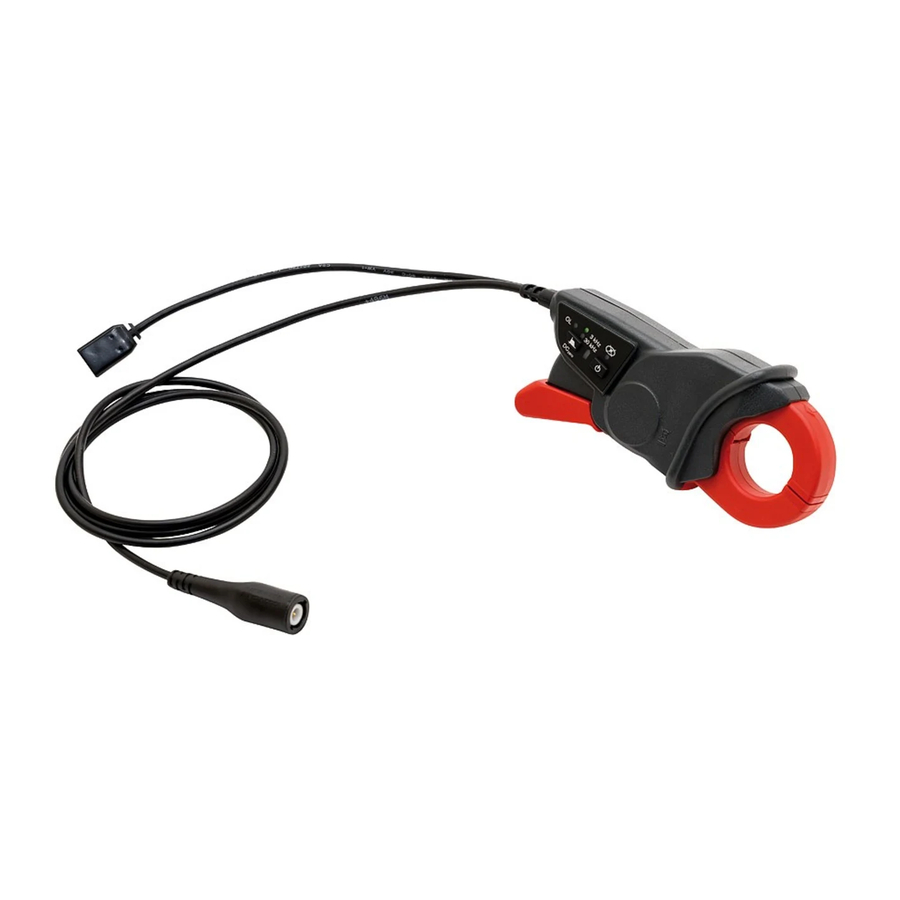
2. BESCHREIBUNG 1. Backen 2. Leiterposition 3. Rutschsicherer Handschutz 4. Tastatur (siehe unten) 5. Trigger zum Öffnen der Backen 6. Verbundene Leitungen: BNC 2m und USB 0,3m 3. TASTEN- UND LED-FUNKTIONEN Diese Tastatur ist in der Abbildung oben mit 4 markiert: Filter 3 kHz (grün) Symbol für Auto Off Filter 30 kHz (grün) -
Seite 38: Tastenfunktionen
3.1. TASTENFUNKTIONEN 3.1.1. START Zum Ausschalten drücken Sie lange auf die Taste . Der Zangenstromwandler MH60 bestätigt mit Daraufhin loslassen . Der eingeschaltete Zangenstromwandler MH60 „ON“ wird mit Leuchtdioden-Lauflicht angezeigt. 3.1.2. STOPP . Der Zangenstromwandler MH60 bestätigt Zum Ausschalten drücken Sie lange (2 s) auf die Taste langes Drücken zuerst mit einer flackernden LED , dann mit allen LEDs. -
Seite 39: Anzeige Der Led
3.2.2. DC NULL VORNEHMEN Der Zangenstromwandler darf nicht geklemmt sein, die Backen müssen geschlossen sein. Drücken Sie lange (2 s) auf die Taste Damit aktivieren Sie die Funktion DC-Null. Während diesem Vorgang leuchtet die LED Danach erlischt die LED wieder, solange kein ERR auftritt, in diesem Fall leuchtet sie weiter. -
Seite 40: Versorgung
1 NiMHAAA-Stab, 1,2 V mit verschweißter Klemme, Anschluss mit Stecker Lebensdauer: mind. 2 Jahre Anzahl Lade-/Entladezyklen: ≥ 300 Dieser Batterietyp kann von CHAUVIN ARNOUX geliefert werden „ Versorgung: mit μUSB-Anschluss, Typ B Höchstverbrauch mit Akku-Ladung): < 170 mA 4.1. GERÄTEAKKU AUFLADEN „... -
Seite 41: Benutzungshinweise
5. BENUTZUNGSHINWEISE 5.1. BENUTZUNG „ Bei nicht isoliertem Leiter die Spannung 300V CAT III bzw. 600V CAT II gegen Erde berücksichtigen. „ Den Zangenstromwandler nur an Leitern mit dem im Dauerbetrieb maximal zulässigen Wert verwenden, also 100 Arms bzw. 140 A Peak. „... -
Seite 42: Technische Spezifikationen
6. TECHNISCHE SPEZIFIKATIONEN 6.1. REFERENZBEDINGUNGEN Einflussgröße Referenzbedingungen Inbetriebnahme vor dem Messen 1 min Umgebungstemperatur 23°C ± 5 K Luftfeuchte 20 % HR bis 75 % HR Frequenz DC bei 400 Hz Leiterposition mittig zwischen den Backen Magnetfeldstärke AC Keines Magnetfeldstärke DC Erdmagnetfeld (<... -
Seite 43: Einsatzbereich
6.3. EINSATZBEREICH 6.3.1. UMGEBUNGSBEDINGUNGEN 1 = Referenzbereich 2 = Einsatzbereich 3 = Lagerbereich Aufgrund des Akkus ist der Lagerungsbereich kleiner. Bei hohen Temperaturen ist die Selbstentladung stärker. Eine vollständige Entleerung beschädigt den Akku. Bevor der Akku längere Zeit hohen Temperaturen ausgesetzt ist, muss er vollständig aufgeladen werden. Das ist in folgenden Fällen nötig: mehr als 3 Monate bei über 50°C, 6 Monate bei über 40°C, 24 Monate bei über 30°C. -
Seite 44: Schwankungen Innerhalb Des Einsatzbereichs
6.3.2. ELEKTROMAGNETISCHE EMPFINDLICHKEIT UND VERTRÄGLICHKEIT Störaussendung und Störimmunität im industriellen Umfeld gemäß IEC61326-1. 6.3.3. SCHUTZ GEGEN STROMSCHLAG Der Zangenstromwandler Typ A ist im Griffbereich bei Normalbetrieb durch eine doppelte oder verstärkte Isolierung geschützt, ebenso zwischen Primär und Sekundärausgang, sowie zwischen USB- Versorgungsanschluss und BNC-Ausgang. -
Seite 45: Grenzwertbedingungen
(1) Leiter liegt außerhalb der Backen aber parallel zur Leiterposition in den Backen. (2) Messung nach Entmagnetisierung des Zangenstromwandlers. Dafür AC I = 0 einstellen und schrittweise den Wert auf I = 40A steigern. Den Wert schrittweise auf I = 0 reduzieren. 6.4. -
Seite 46: Baudaten
7. BAUDATEN Betroffener Bauteil Technische Daten Hinweis Abmessungen 138 x 49 x 28 mm Gesamtmaße Zange Gewicht ca. 200 g mit Kabel und Akku Gehäuse V1 (UL94) Selbstverlöschender Backen V0 (UL94) Werkstoff Kabel V0 (UL94) BNC und USB max. Öffnung 27 mm Farbe rot 1 Kabel mit Ø... -
Seite 47: Akku Austauschen
7.1. AKKU AUSTAUSCHEN „ Bestellen Sie einen neuen Akku (Art. Nr. P01296049). „ USB-Ladegerät abnehmen und den Zangenstromwandler von allen Stromkreisen abtrennen. „ Die beiden Schrauben vom Gehäusedeckel abschrauben. „ Den 2-poligen Akkuanschluss suchen und abstecken. „ Den Akku horizontal herausnehmen und aus der Klammer nehmen. „... -
Seite 48: Justieren Der Verstärkung Am
7.2. JUSTIEREN DER VERSTÄRKUNG AM MH 60 Stellen Sie sicher, dass Sie für diesen Vorgang technisch versiert genug sind. Warnhinweis: Diese Einstellung ist nur vorzunehmen, wenn der Verstärkungskoeffizient eindeutig außerhalb der Toleranz liegt. Vorher überprüfen, dass die Backen sich frei bewegen können und dass die Spalte sauber ist. -
Seite 49: Garantie
8. GARANTIE Unsere Garantie erstreckt sich, soweit nichts anderes ausdrücklich gesagt ist, auf eine Dauer von zwölf Monaten ab dem Zeitpunkt der Bereitstellung des Geräts (Auszug aus unseren allg. Verkaufsbedingungen. Erhältlich auf Anfrage). Eine Garantieleistung ist in folgenden Fällen ausgeschlossen: „... -
Seite 50: Italiano
ITALIANO Avete appena acquistato une pinza per oscilloscopio MH 60 e vi ringraziamo della vostra fiducia. Per ottenere le migliori prestazioni dal vostro strumento: „ Leggete attentamente il presente manuale d’uso, „ Rispettate le precauzioni d’uso. ATTENZIONE, rischio di PERICOLO! L’operatore deve consultare il presente manuale d’uso ogni volta che vedrà... - Seite 51 7.1. Sostituzione dell’accumulatore ..63 3.2. Funzioni del tasto Filtro ..54 7.2. Procedura di regolazione del 3.3. Indicazione del LED ....55 guadagno della pinza MH 60 ..64 3.4. Indicazioni di LED BAT ....55 8. GARANZIA ..........65 4. ALIMENTAZIONE ........56 4.1. Ricarica dell’accumulatore interno ..........56...
-
Seite 52: Introduzione
1. INTRODUZIONE 1.1. PRESENTAZIONE La pinza è una sonda di corrente per oscilloscopio che utilizza una cella ad effetto Hall e che permette la misura di corrente continua o alternata fino a 100 Aeff senza intervento sull’impianto elettrico (interruzione della corrente da misurare). È un trasduttore a uscita tensione. Questa pinza amperometrica, a toro rotondo con traferro, permette una misura rapida della corrente nei conduttori ;... -
Seite 53: Descrizione
2. DESCRIZIONE 1. Ganasce 2. Passaggio del conduttore 3. Dispositivo anti-scivolo di protezione 4. Tastiera (v. più avanti) 5. Grilletto d’apertura 6. Cavi solidali: BNC 2 m e USB 0,3 m 3. FUNZIONI DEI TASTI E DEI LED Questa tastiera è il riferimento 4 della seguente figura: Filtro 3 kHz (verde) Simbolo Auto Off Filtro 30 kHz (verde) -
Seite 54: Funzioni Del Tasto
. La pinza MH 60 riscontra con il LED . Rilasciare allora . Lo statuto «ON» della pinza MH 60 è indicato dall’accensione sequenziale del LED «BAT». 3.1.2. ARRESTARE (2 s). La pinza MH 60 riscontra la pressione lunga con... -
Seite 55: Indicazione Del Led
3.2.2. EFFETTUARE IL DC-ZERO La pinza non deve essere clampata, le ganasce devono essere chiuse. Effettuare una pressione lunga sul tasto (2 s circa). La funzione DC-Zero è allora attivata. Durante il processo, il LED è acceso. Alla fine del processo, se non appare ERR, il LED si spegne. -
Seite 56: Alimentazione
Durata di vita: 2 anni minimo Numero di cicli di ricarica: ≥ 300 Questo tipo d’accumulatore può essere approvvigionato presso CHAUVIN ARNOUX. „ Alimentazione: mediante la presa µUSB, Tipo B Consumo maxi (con carica accumulatore): < 170 mA 4.1. RICARICA DELL’ACCUMULATORE INTERNO „... -
Seite 57: Modalità Operativa
5. MODALITÀ OPERATIVA 5.1. MESSA IN OPERA „ Rispettare la tensione di 300 V (CAT III) o 600 V CAT II) rispetto alla terra, di un conduttore non isolato. „ Utilizzare la pinza su conduttori la cui corrente è inferiore o uguale al valore massimo autorizzato in regime permanente, ossia 100 Aeff o 140 A cresta. -
Seite 58: Caratteristiche Tecniche
6. CARATTERISTICHE TECNICHE 6.1. CONDIZIONI DI RIFERIMENTO Grandezza d’influenza Condizioni di riferimento Messa in marcia prima della misura 1 mn Temperatura ambiente 23°C ± 5 K Umidità 20 % Ur al 75 % Ur Frequenza di DC a 400 Hz Posizione del conduttore centrato nelle ganasce Campo magnetico AC esterno... -
Seite 59: Campo Nominale D'utilizzo
6.3. CAMPO NOMINALE D’UTILIZZO 6.3.1. CONDIZIONI AMBIENTALI 1 = Campo di riferimento 2 = Campo di funzionamento 3 = Campo di stoccaggio Il campo di stoccaggio è ridotto a causa della presenza di un accumulatore. A temperatura elevata, la corrente di autoscarica è più forte. È la scarica profonda che deteriora l’accumulatore. Occorre quindi pre-caricare completamente l’accumulatore prima di un’esposizione durevole a temperature elevate. - Seite 60 6.3.2. COMPATIBILITÀ E SUSCETTIBILITÀ ELETTROMAGNETICHE Conforme all’IEC 61326-1 per l’emissione e l’immunità in uso industriale. 6.3.3. PROTEZIONE CONTRO LE SCOSSE ELETTRICHE Pinza di tipo A a doppio isolamento o isolamento rinforzato nella parte prensile in utilizzo normale, e doppio isolamento o isolamento rinforzato fra il primario e l’uscita secondaria e la parte collegata d’alimentazione USB e l’uscita BNC.
-
Seite 61: Condizioni - Limiti
6.4. CONDIZIONI - LIMITI - Sovraccarico: 1500 ADC per 1 mn. 6.5. LIMITI IN FREQUENZA SECONDO LA CORRENTE DI MISURA In utilizzo normale 100 Aeff permanente fino alla frequenza di 45 kHz. Derating in frequenza oltre 100 A 45 kHz. Secondo la formula:... -
Seite 62: Caratteristiche Meccaniche
7. CARATTERISTICHE MECCANICHE Tipo Parte interessata Caratteristiche Nota dimensioni 138 x 49 x 28 mm fuori tutto Pinza con cavo e peso circa 200 g accumulatore scatola V1 (UL94) Autospegnimento ganasce V0 (UL94) cavi V0 (UL94) BNC e USB Apertura massima 27 mm Colore: rosso 1 cavo di Ø... -
Seite 63: Sostituzione Dell'accumulatore
7.1. SOSTITUZIONE DELL’ACCUMULATORE „ Procurarsi l’accumulatore di ricambio (Rif. P01296049). „ Disinserire il caricatore USB e scollegare la pinza da qualsiasi circuito. „ Rimuovere le due viti di chiusura della scatola. „ Identificare il connettore Accumulatore due punti e scollegarlo. „... -
Seite 64: Procedura Di Regolazione Del Guadagno Della Pinza Mh 60
7.2. PROCEDURA DI REGOLAZIONE DEL GUADAGNO DELLA PINZA MH 60 Accertarsi che il proprio livello tecnico sia sufficiente per realizzare questa operazione. Avvertenza: Intraprendere questa regolazione solo se il coefficiente di guadagno è manifestamente fuori tolleranza. Verificare dapprima che i movimenti delle ganasce non siano ostacolati e che il traferro sia pulito. -
Seite 65: Garanzia
8. GARANZIA Salvo stipulazione espressa la nostra garanzia si esercita, dodici mesi a decorrere dalla data di messa a disposizione del materiale. L’estratto delle nostre Condizioni Generali di Vendita sarà comunicato su domanda. La garanzia non si applica in seguito a: „... -
Seite 66: Español
ESPAÑOL Usted acaba de adquirir una pinza para osciloscopio MH 60 y le agradecemos la confianza que ha depositado en nosotros. Para conseguir las mejores prestaciones de su instrumento: „ lea atentamente este manual de instrucciones, „ respete las precauciones de uso. -
Seite 67: Precauciones De Uso
3.1. Funciones de la tecla ..70 7.1. Cambio de acumulador ....79 7.2. Procedimiento de ajuste de 3.2. Funciones de la tecla Filtro la ganancia de la MH 60 ....80 3.3. Indicación del LED ....71 8. GARANTÍA ..........81 3.4. Indicaciones de LED BAT ..71... -
Seite 68: Introducción
1. INTRODUCCIÓN 1.1. PRESENTACIÓN La pinza MH 60 es una sonda de corriente para osciloscopio que utiliza une célula de efecto Hall que permite medir la corriente continua o alterna hasta 100 Arms sin intervenir en la instalación eléctrica (corte de la corriente a medir). Es un transductor con salida de tensión. -
Seite 69: Descripción
2. DESCRIPCIÓN 1. Mordazas 2. Paso del conductor 3. Protección antideslizamiento 4. Teclado (véase abajo) 5. Gatillo de abertura 6. Cables solidarios: BNC 2 m y USB 0,3 m 3. FUNCIONES DE LAS TECLAS Y DE LOS LED Este teclado es la referencia 4 de la figura más arriba: Filtro 3 kHz (verde) Símbolo Auto Off Filtro 30 kHz (verde) -
Seite 70: Funciones De La Tecla
Mantenga pulsada la tecla . La pinza MH 60 confirma con el LED . Suelte entonces El estado «ON» de la pinza MH 60 está indicado por el encendido secuencial del LED «BAT». 3.1.2. APAGAR Mantenga pulsada la tecla (2 s). La pinza MH 60 confirma la pulsación larga por el parpadeo rápido del LED... -
Seite 71: Indicación Del Led
De lo contrario, se queda encendido. El estado ERR lo causa normalmente la circulación de una corriente en un conductor abrazado. La pinza MH 60 integra un magnetómetro que reduce la influencia de los campos exteriores, en particular el campo terrestre. -
Seite 72: Fuente De Alimentación
Vida útil: 2 años mínimo Número de circos de carga: ≥ 300 Este tipo de acumulador se puede adquirir en CHAUVIN ARNOUX „ Fuente de alimentación: a partir de la toma µUSB, Tipo B Consumo máx. (con carga acumulador): < 170 mA 4.1. -
Seite 73: Modo Operativo
5. MODO OPERATIVO 5.1. PRIMERA PUESTA EN MARCHA „ Respete la tensión de 300 V (CAT III) o 600 V (CAT II) con respecto a la tierra, de un conductor no aislado. „ Utilice la pinza en conductores cuya corriente es inferior o igual al valor máximo autorizado en régimen permanente, 100 Arms o 140 Arms pico. -
Seite 74: Características Técnicas
6. CARACTERÍSTICAS TÉCNICAS 6.1. CONDICIONES DE REFERENCIA Magnitud de influencia Condiciones de referencia Puesta en marcha antes de una medida 1 mn Temperatura ambiente 23°C ± 5 K Humedad 20 % HR a 75 % HR Frecuencia del CC a 400 Hz Posición del conductor centrado dentro de las mordazas Campo magnético CA exterior... -
Seite 75: Rango Nominal De Utilización
6.3. RANGO NOMINAL DE UTILIZACIÓN 6.3.1. CONDICIONES AMBIENTALES 1 = Rango de referencia 2 = Rango de funcionamiento 3 = Rango de almacenamiento El rango de almacenamiento se muestra reducido por la presencia de un acumulador. A altas temperaturas, la corriente de autodescarga es más fuerte. La descarga profunda deteriora el acumulador. Por lo tanto se debe precargar el acumulador por completo previamente a una exposición duradera a altas temperaturas. - Seite 76 6.3.2. COMPATIBILIDAD Y SUSCEPTIBILIDAD ELECTROMAGNÉTICAS Conforme al IEC 61326-1 para la emisión e inmunidad en uso industrial. 6.3.3. PROTECCIÓN CONTRA LAS DESCARGAS ELÉCTRICAS Pinza de tipo A de doble aislamiento o aislamiento reforzado en la parte por la que se maneja en uso normal, y aislamiento doble o aislamiento reforzado entre el primario y la salida secundaria y la parte de conectores de alimentación USB y la salida BNC.
-
Seite 77: Condiciones Límites
6.4. CONDICIONES LÍMITES - Sobrecarga: 1.500 ACC durante 1 mn. 6.5. LÍMITES EN FRECUENCIA SEGÚN LA CORRIENTE DE MEDIDA En uso normal 100 Arms permanente hasta la frecuencia de 45 kHz. Derating en frecuencia más allá 100 A 45 kHz. Según la fórmula:... -
Seite 78: Características Mecánicas
7. CARACTERÍSTICAS MECÁNICAS Tipo Parte correspondiente Características Nota dimensiones 138 x 49 x 28 mm total Pinza con cable y peso 200 g aprox. acumulador carcasa V1 (UL94) Resistencia al fuego mordazas V0 (UL94) cables V0 (UL94) BNC y USB abertura máxima 27 mm color rojo... -
Seite 79: Cambio De Acumulador
7.1. CAMBIO DE ACUMULADOR „ Adquiera al acumulador de recambio (ref. P01296049). „ Desconecte el cargador USB y quite la pinza de cualquier circuito. „ Quite los dos tornillos de cierre de la carcasa. „ Identifique el conector del acumulador dos puntos y desconéctelo. „... -
Seite 80: Procedimiento De Ajuste De La Ganancia De La Mh 60
7.2. PROCEDIMIENTO DE AJUSTE DE LA GANANCIA DE LA MH 60 Asegúrese de tener un conocimiento técnico suficiente para realizar esta operación. Advertencia: Realice este ajuste sólo si el coeficiente de ganancia está evidentemente fuera de tolerancia. Compruebe previamente que nada obstaculiza las mordazas en sus movimientos y que el entrehierro está... -
Seite 81: Garantía
8. GARANTÍA Nuestra garantía tiene validez, salvo estipulación expresa, durante doce meses a partir de la fecha de entrega del material. El extracto de nuestras Condiciones Generales de Venta se comunica a quien lo solicite. La garantía no se aplicará en los siguientes casos: „... - Seite 82 FRANCE INTERNATIONAL Chauvin Arnoux Chauvin Arnoux 12-16 rue Sarah Bernhardt Tél : +33 1 44 85 44 38 92600 Asnières-sur-Seine Fax : +33 1 46 27 95 69 Tél : +33 1 44 85 44 85 Fax : +33 1 46 27 73 89 Our international contacts info@chauvin-arnoux.com...