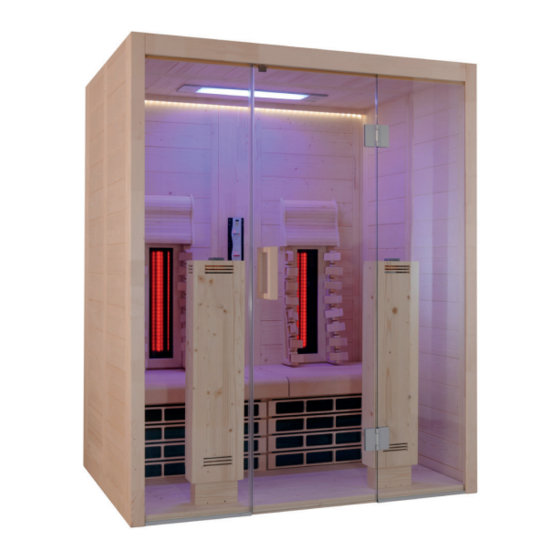
Seite 1
Infrared cabin VitaMy 164 164 x 120 x 202 cm INSTRUCTIONS FOR INSTALLATION AND USE English VITAMY-164-B / 1-037-765: VitaMy 164 Basic VITAMY-164-S&L / 1-037-768: VitaMy 164 S&L Version 03/21 ID no. 1-038-133...
3.3. Product functions 4. Installation of the VitaMy 164 infrared cabin 4.1. Necessary tools 4.2. Infrared cabine VitaMy 164 Basic / BT / S&L parts list 4.3. Cabin installation 4.4. Installation of the infrared control 4.5. Installing the LED strip 4.6.
These installation and operating instructions can also be found in the downloads section of our website: www.sentiotec.com/downloads. Symbols used for warning notices In these instructions for installation and use, a warning notice located next to an activity indicates that this activity poses a risk.
Instructions for installation and use p. 4/40 2. Important information for your safety The infrared cabin has been produced in accordance with the safety regulations applicable for technical units. However, hazards may occur during use. Therefore adhere to the following safety informa- tion and the specific warning notices in the individual chapters.
Instructions for installation and use p. 5/40 2.2. Safety information ● Installation and connection of the electrical parts (control unit, radiator, etc.) may only be performed when the power supply is disconnected. ● Also comply with the regulations applicable at the installation location.
Instructions for installation and use p. 6/40 3. Product description 3.1. Scope of delivery VitaMy 164 Basic (1-037-765) ● 1x Infrared cabine VitaMy 164 ● 1x 1-037-357 / Power unit wave.com4 Infra ● 1x 1-012-222 / Control panel wave.com4 Infra ●...
The control unit only supports the operating mode “Intensity mode”. sound & light colour light (only version VitaMy 164 S&L) The sound & light colour light lets music be played via a USB stick and the cabins be lit with different colours.
Instructions for installation and use p. 8/40 4. Installation of the VitaMy 164 infrared cabin Before you start work, check the parts list to see whether all the items have actually been delivered. If individual items are missing, notify your dealer within 14 days after receipt of the cabin.
Instructions for installation and use p. 9/40 4.2. Infrared cabine VitaMy 164 Basic / S&L parts list No.of Name Dimensions Items Base frame 1 Rear floor frame 164 x 9 x 4 cm 2 Floor frame 114 x 9 x 4 cm...
Instructions for installation and use p. 11/40 4.3. Cabin installation Observe the layout “floor plan” on page 39. Installing the floor frame Fig. 1: Placing the three floor frame elements Fig. 2: Connect the floor frame elements Hit the plastic swallows gently with a hammer at the two corners of the floor frame until they are flush with the groove of the element.
Seite 12
Instructions for installation and use p. 12/40 Wall element installation Begin the installation of the wall elements with Wall Elements W2 and W3 or W4 and W5 respectively (see the chapter Layout on page 43). The wall elements are connected with the "multi-clips" with the corner posts. Make sure that the elements with the opening for the infrared radiators W3 and W4 are used at the back of the cabin.
Seite 13
Instructions for installation and use p. 13/40 Fig. 4: Connect the wall element with the corner post Insert the corner post from top to bottom on the wall elements. When doing so, pay attention to the correct alignment of the "multi-clips" (see Fig. Abb. 4). The corner post has to be flush with the wall elements.
Seite 14
Instructions for installation and use p. 14/40 Fig. 6: Install the electrical element in place After you have put the electric element in place, continue with the second corner. Fig. 7: Pre-assembled rear wall...
Seite 15
Instructions for installation and use p. 15/40 Fig. 8: Installation of the two front corner- Installation of side wall elements posts with a groove for glass W1 and W6 Fig. 9: Installed wall elements...
Seite 16
Instructions for installation and use p. 16/40 Glass element installation Insert the U-profile flush to the glass plate. When doing so, pay attention to the flush meeting of the profiles with the glass on the side where the door will be. WARNING! After the cabin has been positioned correctly, glue the U-profiles with silicone or installation glue to the floor.
Seite 17
Instructions for installation and use p. 17/40 Fig. 11: Inserting the glass sheet in the groove of the corner post Slide the glass gently into the groove of corner post. Do this for both glass side panels. Fig. 12: Installing the skirting over the glass front To install the skirting, press the two front corner posts outwards and insert the skirting by means of dowel joints.
Seite 18
Instructions for installation and use p. 18/40 Fig. 13: Attaching the skirting Attach skirting by squeezing the side wall elements until the anchors are no longer visible. Roof element installation Check the right angle alignment of the cabin in the corners or use the measuring tape to measure the two diagonals of the cabin;...
Seite 19
Instructions for installation and use p. 19/40 Fig. 15: Roof support slats Fig. 16: Installing the roof element in the back with the fan cut-out Fig. 17: Installing the roof element in the front...
Seite 20
Instructions for installation and use p. 20/40 After the roof elements have been inserted, they have to be screwed in with the roof support slat. Fig. 18: Attaching the roof element Screws 14 units: 3.5 x 35 Door installation Fig. 19: Installing the door insulation strips The insulation is placed on the glass element which does not have any holes for the door fittings.
Seite 21
Instructions for installation and use p. 21/40 Fig. 20: Door handle installation First, set the two silicone inserts in the holes for the door handle in the glass element. Then, screw the two handles together carefully. Insert silicone rings into the holes. Screws 2 units: 3.5 x 70 The bottom hole of the door handle is at a height of 92.5 cm.
Seite 22
Instructions for installation and use p. 22/40 Fig. 21: Installation of Door Fitting 1 Screw the two door fittings onto the fix-glass element, making sure of the straight alignment of the fittings and that the door opens to the outside. The fittings are aligned through the adjustment/rotation of the two plastic rings.
Seite 23
Instructions for installation and use p. 23/40 Fig. 23: Door magnet installation The magnet for the door has to be on the side to which the door opens. Mount the magnet on the appropriate side, if appropriate. Cut the door insulation over the recess for the magnet with a sharp knife and expose the recess.
Seite 24
Instructions for installation and use p. 24/40 Fig. 25: Completed wall elements and roof elements...
Seite 25
Instructions for installation and use p. 25/40 Fig. 26: Put the cabin floor in place Front radiator installation Fig. 27: Attach the front radiator in place Make sure that the cables of the front radiator are exposed at the bottom and are not pinched or damaged by the cabin floor.
Seite 26
Instructions for installation and use p. 26/40 After the radiators are locked in at the bottom, attach each one firmly with a 90° rotation on the Allen screws in a clockwise direction at the four attachment points. Fig. 28: Attach the front radiator in place Fig.
Seite 27
Instructions for installation and use p. 27/40 Installation of the bench cushion and the IR thermal plate Fig. 30: Installation of the bench cushion Screws 6 units: 5 x 70 Screw in the bench cushion left and right in the cabin as well as the bench cushion bar on the electric element with 2 screws each.
Seite 28
28/40 Fig. 32: Installation of the IR thermal plate VitaMy 164 Install the two IR thermal plates VitaMy 164 in the U-strips. The recess is used to perform the management of the front beam (see Fig. 35) When inserting the IR thermal plate, pay attention to the cable of the switch;...
Seite 29
Instructions for installation and use p. 29/40 Fig. 35: Inserting the bench Place the bench on the support slats. Ventilation installation Fig. 34: Ventilation installation Screw together the base element of the Then screw the wooden plate into place vent and the 3 enclosed screws. and secure the screw from the outside with the plastic cap.
Seite 30
Instructions for installation and use p. 30/40 Installation of the read radiator Fig. 36: Install the rear radiator (infrared radiator ECO 350) Screws 8 units: 3 x 18 Put the two radiators into the cutout from inside. Screw the radiators into place with 4 screws each.
Instructions for installation and use p. 31/40 4.4. Installation of the infrared control For the installation, commissioning and operation, follow the instructions which are included which the control unit. The control unit only supports the operating mode “Intensity mode”. Installing the control panel Install the control panel in the designated place on the back wall of the cabin.
Seite 32
Instructions for installation and use p. 32/40 Connecting the power supply The power supply of the control unit is placed under the bench of the cabin and is connected as follows. Fig. 39: Power supply connections Plug Description wave.com4 Infra control panel IR Heating Group 1 IR Heating Group 2 Mains connection...
Seite 33
Instructions for installation and use p. 33/40 Arrangement of the heating groups The power supply of the control unit is placed under the bench of the cabin and is connected as follows. Heating Group 1: Front radiator left, read radiator left, wall radiator left (above switch) Heating Group 2: Front radiator right, read radiator right, wall radiator right (above switch)
Instructions for installation and use p. 34/40 4.5. Installing the LED strip Fig. 41: Attaching the LED strip 3 Screws: 3.5 x 50 mm Screw the LED cover strip tight from above (pre-drilled) LED-SET WC4-INFRA 1-052-935 Connecting the LED RGBW WHITE Fig.
Instructions for installation and use p. 35/40 4.6. Installation of the sound & light (only VitaMy 164 S&L) For the installation, commissioning and operation, follow the instructions which are included which the sound & light colour light. Installing the control panel and the USB dock Install the control panel and the USB dock in the designated place on the back wall of the cabin.
Instructions for installation and use p. 36/40 4.7. Installation of the bench After the control unit has been connected, the bench can be fully installed. Fig. 45: Attaching the bench Screws 4 units: 4 x 70 Place the bench on the support slats. Push the seating areas forward. CAUTION! Secure the bench against sliding by using the locking screws on the left and right of the bench cushion as well as on the bench support rail.
Instructions for installation and use p. 37/40 4.9. Installation of the backrests and headrests of the bench Screw in the multi-clips using the mounting template with the accompanying screws. Fig. 48: Installing the backrests of the bench Remove the mounting template and insert the backrests downwards from above onto the brackets until they fit into place.
● Do not use too much moisture when cleaning the cabin and the electronic components. 5.2. Maintenance The VitaMy 164 infrared cabin is maintenance-free. 6. Troubleshooting ● For your own safety, consult your supplier in the event of problems that are not explained in sufficient detail in the installation instructions.
- 25 °C to + 70 °C Ambient temperature: 20 °C to + 30 °C Relative humidity: max. 95% 9. Floor plan Since wood is a natural product, slight dimensional deviations are possible. VitaMy 164 Basic / S&L 164 x 120 x 202 cm Electrical Element...
Seite 40
Instructions for use for the user p. 40/40...
Seite 41
Infrarotkabine VitaMy 164 164 x 120 x 202 cm MONTAGE- UND GEBRAUCHSANWEISUNG Deutsch VITAMY-164-B / 1-037-765: VitaMy 164 Basic VITAMY-164-S&L / 1-037-768: VitaMy 164 S&L Version 03/21 Ident-Nr. 1-038-133...
Seite 42
4.2. Stückliste Infrarotkabine VitaMy 164 Basic / S&L 4.3. Montage der Kabine 4.4. Einbau der Infrarot-Steuerung 4.5. Montage der LED-Leiste 4.6. Einbau der sound & light (nur VitaMy 164 S&L) 4.7. Montage der Bank 4.8. Montage der Abstandleisten der Rückwand 4.9. Montage der Rückenlehnen und Kopfstützen 5.
Sie sie in der Nähe der Infrarotkabine auf. So können Sie jederzeit Informationen zu Ihrer Sicherheit und zur Bedienung nachlesen. Sie finden diese Montage- und Gebrauchsanweisung auch im Download- bereich unserer Webseite auf www.sentiotec.com/downloads. Symbole in Warnhinweisen In dieser Montage- und Gebrauchsanweisung ist vor Tätigkeiten, von denen eine Gefahr ausgeht, ein Warnhinweis angebracht.
Montage- und Gebrauchsanweisung S. 4/40 2. Wichtige Hinweise zu Ihrer Sicherheit Die Infrarotkabine ist nach anerkannten sicherheitstechnischen Regeln gebaut. Dennoch können bei der Verwendung Gefahren entstehen. Befolgen Sie deshalb die folgenden Sicherheitshinweise und die speziellen Warnhinweise in den einzelnen Kapiteln. 2.1.
Montage- und Gebrauchsanweisung S. 5/40 2.2. Sicherheitshinweise ● Montage- und Anschlussarbeiten an elektrischen Teilen (Steue- rung, Strahler,...) dürfen nur im spannungsfreien Zustand durch- geführt werden. ● Beachten Sie auch die örtlichen Bestimmungen am Aufstellort. ● Bei Problemen, die in den Montageanweisungen nicht ausführ- lich genug behandelt werden, wenden Sie sich zu Ihrer eigenen Sicherheit an Ihren Lieferanten.
Dimmen von Licht und einem optionalen Lüfter. Diese Steuerung unterstützt lediglich die Betriebsart „Intensitätsregelung“. sound & light Farblampe (nur Ausführung VitaMy 164 S&L) Die Farblampe sound & light ermöglicht das Abspielen von Musik mittels USB- Stick und Beleuchtung der Kabinen mit verschiedensten Farben.
Montage- und Gebrauchsanweisung S. 8/40 4. Montage der Infrarotkabine VitaMy 164 Kontrollieren Sie, bevor Sie mit der Arbeit beginnen, anhand der Stückliste, ob alle Einzelteile auch tatsächlich mitgeliefert wurden. Sollten Einzelteile aus- nahmsweise fehlen, benachrichtigen Sie spätestens 14 Tage nach Erhalt der Kabine Ihren Händler.
Montage- und Gebrauchsanweisung S. 9/40 4.2. Stückliste Infrarotkabine VitaMy 164 Basic / S&L Az Bezeichnung Maß Bodenrahmen 1 Bodenrahmen hinten 164 x 9 x 4 cm 2 Bodenrahmen 114 x 9 x 4 cm Wandelemente 4 Wandelemente A/A mit Multiclip, W1,W2,W5,W6 193 x 54 x 4 cm 1 Elektroelement je nach Type (siehe Ende Stück-...
Seite 50
13,5 x 2 x 2 cm 1 Schablone für Multiclip Montage Rückenlehne 1 Schablone für Multiclip Montage Glasfront 2 Abstandsleiste Rückwand 202 x 5 x 4 cm 1 Montagematerial 1 Montageanleitung Elektroelement VitaMy 164 Basic 2 Ausschnitte Elektroelement VitaMy 164 - S&L 4 Ausschnitte...
Montage- und Gebrauchsanweisung S. 11/40 4.3. Montage der Kabine Beachten Sie den Grundriss auf Seite 39. Montage des Bodenrahmens Abb. 1: Auflegen der drei Bodenrahmen-Elemente Abb. 2: Bodenelemente verbinden Schlagen Sie die Kunstoffschwalben vorsichtig mit einem Hammer, an den beiden Ecken des Bodenrahmens ein, bis diese bündig mit der Nut des Elements sind.
Seite 52
Montage- und Gebrauchsanweisung S. 12/40 Montage der Wandelemente Beginnen Sie die Montage der Wandelemente mit den Wandelementen W2 und W3 bzw. W4 und W5 (siehe Kapitel Grundriss auf Seite 43). Die Wandelemente werden mit den „Multiclips“ mit den Eckstehern verbunden. Achten Sie darauf, dass die Elemente mit der Öffnung für den Infrarotstrahler W3 u.
Seite 53
Montage- und Gebrauchsanweisung S. 13/40 Abb. 4: Wandelemente mit Ecksteher verbinden Stecken Sie den Ecksteher von oben nach unten auf die Wandelemente. Ach- ten Sie dabei auf die korrekte Ausrichtung der „Multiclips“ (siehe Abb. 4). Der Ecksteher muss bündig mit den Wandelementen sein. Abb.
Seite 54
Montage- und Gebrauchsanweisung S. 14/40 Abb. 6: Elektroelement einsetzen Nachdem Sie das Elektroelement eingesetzt haben, fahren Sie mit der zweiten Ecke fort. Abb. 7: Fertig montierte Rückwand...
Seite 55
Montage- und Gebrauchsanweisung S. 15/40 Abb. 8: Abb. 9: Montage seitliche Wandelemente Montage der beiden vorderen Eck- W1 und W6 steher mit Nut für Glas Abb. 10: Montierte Wandelemente...
Seite 56
Montage- und Gebrauchsanweisung S. 16/40 Montage der Glaselemente Stecken Sie das U-Profil bündig auf die Glasplatte. Achten Sie dabei auf den bün- digen Abschluss der Profile mit dem Glas an jener Seite, an der die Tür sein wird. WARNUNG! Kleben Sie nachdem die Kabine korrekt positioniert ist, die U-Profile mit Silikon oder Montagekleber an den Boden.
Seite 57
Montage- und Gebrauchsanweisung S. 17/40 Abb. 12: Einsetzen der Glasscheibe in die Nut des Eckstehers Schieben Sie das Glas vorsichtig in die Nut des Eckstehers. Führen Sie dies für beide Glas-Seitenteile durch. Abb. 13: Montage Massivleiste über der Glasfront Für die Montage der Massivleiste die beiden vorderen Ecksteher nach außen drücken und die Massivleiste mittles Dübelverbindungen einsetzen.
Seite 58
Montage- und Gebrauchsanweisung S. 18/40 Abb. 14: Fixieren der Massivleiste Die Massivleiste durch zusammendrücken der seitlichen Wandelemente fixieren, bis die Dübel nicht mehr sichtbar sind. Montage der Dachelemente Kontrollieren Sie die rechtwinkelige Ausrichtung der Kabine in den Ecken oder messen mit dem Rollband die beiden Diagonalen der Kabine, wenn diese gleich lang sind, ist die Kabine korrekt ausgerichtet.
Seite 59
Montage- und Gebrauchsanweisung S. 19/40 Abb. 16: Dachauflageleisten Abb. 17: Einlegen Dachelement hinten mit Lüfterausschnitt Abb. 18: Einlegen Dachelemente vorne...
Seite 60
Montage- und Gebrauchsanweisung S. 20/40 Nachdem die Dachelemente eingelegt wurden, müssen diese mit der Dachauf- lageleiste verschraubt werden. Abb. 19: Befestigen der Dachelemente Schrauben 14 Stk: 3,5 x 35 Montage der Türe Abb. 20: Aufsetzen der Türdichtung Die Dichtung wird auf das Glaselement aufgesetzt, welches keine Bohrungen für die Türbeschläge besitzt.
Seite 61
Montage- und Gebrauchsanweisung S. 21/40 Abb. 21: Montage Türgriff Setzen Sie zuerst die beiden Silikoneinlagen in die Bohrungen für den Türgriff am Glaselement ein. Danach verschrauben Sie die beiden Griffe vorsichtig miteinander. Silikonringe in die Bohrungen einlegen Schrauben 2 Stk: 3,5 x 70 Die untere Bohrung des Türgriffs ist in 92,5 cm Höhe.
Seite 62
Montage- und Gebrauchsanweisung S. 22/40 Abb. 22: Montage Türbeschläge 1 Schrauben Sie die beiden Türbeschläge am Fix-Glaselement fest, achten sie dabei auf die gerade Ausrichtung der Beschläge und darauf, dass die Öffnung der Türe nach außen erfolgt. Die Ausrichtung der Beschläge wird durch die Justierung / Drehung der beiden Kunstoffringe vorgenommen.
Seite 63
Montage- und Gebrauchsanweisung S. 23/40 Abb. 24: Montage Türmagnet Der Magnet für die Tür muss auf jener Seite sein, an der die Türe öffnet. Montieren Sie den Magnet ggfs. auf die entsprechende Seite. Schneiden Sie die Türdichtung über der Ausnehmung für den Magnet mit einem scharfen Messer durch und legen die Ausnehmung frei.
Seite 64
Montage- und Gebrauchsanweisung S. 24/40 Abb. 26: Fertige Kabinenwände und Dachelemente...
Seite 65
Montage- und Gebrauchsanweisung S. 25/40 Abb. 27: Kabinenboden einlegen Montage der Frontstrahler Abb. 28: Frontstrahler fixieren Achten Sie darauf, dass die Kabel der Frontstrahler frei am Boden liegen und nicht durch den Kabinenboden eingeklemmt oder beschädigt werden.
Seite 66
Montage- und Gebrauchsanweisung S. 26/40 Nachdem die Strahler am Boden eingerastet sind, fixieren Sie diese jeweils mit einer Drehung um 90° an den Imbusschrauben im Uhrzeigersinn an den vier Befestigungspunkten. Abb. 29: Fronstrahler fixieren Abb. 30: Einlegen der Specksteinschalen...
Seite 67
Montage- und Gebrauchsanweisung S. 27/40 Montage der Bankauflage und der IR-Wärmeplatten Abb. 31: Montage der Bankauflage Schrauben 6 Stk: 5 x 70 Schrauben Sie links und rechts in der Kabine die Bankauflagen und am Elekt- roelement die Bankauflage-Leiste mit je 2 Schrauben fest. Abb.
Seite 68
S. 28/40 Abb. 33: Einsetzen der IR-Wärmeplatte VitaMy 164 Setzen Sie die den beide IR-Wärmeplatten VitaMy 164 in die U-Leisten ein. Die Ausnehmung dient zur Durchführung der Leitung des Frontstrahles (siehe Abb. 35) Achten Sie beim Einsetzen der IR-Wärmeplatte auf die Kabel der Schalter, diese dürfen nicht eingeklemmt oder beschädigt werden.
Seite 69
Montage- und Gebrauchsanweisung S. 29/40 Abb. 36: Einlegen der Sitzbank Legen Sie die Bank auf die Auflageleisten. Montage der Entlüftung Abb. 35: Montage der Entlüftung Schrauben Sie das Basiselement der Schrauben Sie anschließend das Holz- Entlüftung mit den 3 beiliegend Schrau- teller ein und sichern Sie die Schraube ben fest.
Seite 70
Montage- und Gebrauchsanweisung S. 30/40 Montage der Rückenstrahler Abb. 37: Rückenstrahler (Infrarot-Strahler ECO 350) montieren Schrauben 8 Stk: 3 x 18 Setzten Sie die beiden Strahler von innen in den Ausschnitt ein. Schrauben Sie die Strahler mit je 4 Schrauben fest. VORSICHT! Achten Sie darauf, dass der Anschlusskasten der Strahler auf der Oberseite ist!
Montage- und Gebrauchsanweisung S. 31/40 4.4. Einbau der Infrarot-Steuerung Beachten Sie für die Montage, Inbetriebnahme und Bedienung die An- leitung, welche der Steuerung beiliegt. Diese Steuerung unterstützt lediglich die Betriebsart „Intensitätsregelung“. Montage des Bedienteils Montieren Sie das Bedienteil an die vorgesehene Stelle in der Rückwand der Kabine.
Montage- und Gebrauchsanweisung S. 32/40 Anschluss des Leistungsteils Das Leistungsteil der Steuerung wird unter der Bank der Kabine platziert und wie folgt angeschlossen. Abb. 40: Anschlüsse Leistungsteil Stecker Beschreibung wave.com4 Infra Bedienteil IR-Heizgruppe 1 IR-Heizgruppe 2 Netzanschluss Lüfteranschluss (schwarz) - optional Lichtanschluss (grün)
Seite 73
Montage- und Gebrauchsanweisung S. 33/40 Zuordnung der Heizgruppen Das Leistungsteil der Steuerung wird unter der Bank der Kabine platziert und wie folgt angeschlossen. Heizgruppe 1: Frontstahler links, Rückenstrahler links, Wadenstrahler links (über Schalter) Heizgruppe 2: Frontstahler rechts, Rückenstrahler rechts, Wadenstrahler rechts (über Schalter) Die Anordnung kann beinahe beliebig den eigenen Wünschen angepasst werden.
Montage- und Gebrauchsanweisung S. 34/40 4.5. Montage der LED-Leiste Abb. 42: LED-Leiste fixieren 3 Schrauben: 3.5 x 50 mm Schrauben Sie die LED Abdeckleiste von oben fest (vorgebohrt) LED-SET WC4-INFRA 1-052-935 Anschluss des LED RGBW WHITE Abb. 43: Verbinden des LED RGBW mit der Steuerung WC4 Infra LED Dimmer Leistungsteil...
Montage- und Gebrauchsanweisung S. 35/40 4.6. Einbau der sound & light (nur VitaMy 164 S&L) Beachten Sie für die Montage, Inbetriebnahme und Bedienung die An- leitung welche der sound & light Farblampe beiliegt. Montage des Bedienteils und des USB-Docks Montieren sie das Bedienteil und das USB-Dock an die vorgesehen Stellen in der Rückwand der Kabine.
Montage- und Gebrauchsanweisung S. 36/40 4.7. Montage der Bank Nachdem die Steuerung fertig angeschlossen ist, kann die Bank fertig montiert werden. Abb. 46: Fixieren der Sitzbank Schrauben 4 Stk: 4 x 70 Legen Sie die Bank auf die Auflageleisten. Schieben Sie die Sitzflächen nach vorne.
Montage- und Gebrauchsanweisung S. 37/40 4.9. Montage der Rückenlehnen und Kopfstützen Schrauben Sie die Multiclips mit Hilfe der Montageschablone mit den beiliegen- den Schrauben fest. Abb. 49: Montage Rückenlehnen Stecken Sie abschließend die Rückenlehnen von oben nach unten auf die Hal- terungen bis diese einrasten.
Wasser. ● Reinigen Sie die Kabine und die elektronischen Komponenten nicht zu feucht. 5.2. Wartung Die Infrarotkabine VitaMy 164 ist wartungsfrei. 6. Problemlösung ● Bei Problemen, die in den Montageanweisungen nicht ausführlich genug behandelt werden, wenden Sie sich zu Ihrer eigenen Sicherheit an Ihren Lieferanten.
Lagertemperatur: - 25 °C bis + 70 °C Umgebungstemperatur: 20 °C bis + 30 °C Luftfeuchtigkeit: max. 95% 9. Grundriss Da Holz ein Naturprodukt ist, sind geringfügige Maßabweichungen möglich. VitaMy 164 Basic / S&L 164 x 120 x 202 cm...
Seite 80
Gebrauchsanweisung für den Anwender S. 40/40...
Seite 81
Cabine infrarouge VitaMy 164 164 x 120 x 202 cm INSTRUCTIONS DE MONTAGE ET MODE D’EMPLOI Français VITAMY-164-B / 1-037-765 : VitaMy 164 Basic VITAMY-164-S&L / 1-037-768 : VitaMy 164 S&L Version 03/21 d’ident. 1-038-133...
Seite 82
4.3. Montage de la cabine 4.4. Montage de la commande infrarouge 4.5. Montage de la barre à LED 4.6. Montage de la lampe sound & light (uniquement VitaMy 164 S&L) 34 4.7. Montage du banc 4.8. Montage des barres d’écartement de la paroi arrière 4.9.
à votre sécurité. Ces instructions de montage et ce mode d’emploi sont également dis- ponibles dans la rubrique de téléchargement de notre site Internet www.sentiotec.com/downloads. Symboles d’avertissement Dans les instructions de montage et le mode d’emploi, un avertissement précède les activités représentant un danger.
Instructions de montage et mode d‘emploi p. 4/40 2. Remarques importantes pour votre sécurité La cabine infrarouge est conçue selon des règles techniques de sécurité reconnues. Cependant, des dangers peuvent survenir lors de l’utilisation. C’est pourquoi vous devez suivre les consignes de sécurité...
Instructions de montage et mode d‘emploi p. 5/40 2.2. Consignes de sécurité ● Les travaux de montage et de raccordement sur les parties électriques (commande, radiateurs...) doivent être effectués uniquement lorsque l’appareil n’est pas sous tension. ● Respectez également les dispositions légales du lieu d’installation. ●...
Instructions de montage et mode d‘emploi p. 6/40 3. Description du produit 3.1. Étendue de la livraison VitaMy 164 Basic (1-037-765) ● 1x cabine infrarouge VitaMy 164 ● 1x 1-037-357 / Module de puissance wave.com4 Infra ● 1x 1-012-222 / Module de commande wave.com4 Infra ●...
Cette commande prend en charge uniquement le mode « Régulation d’intensité ». Lampe couleur sound & light (uniquement version VitaMy 164 S&L) La lampe couleur sound & light permet de jouer de la musique au moyen d’une clé USB et d’éclairer les cabines avec une grande variété de couleurs.
Instructions de montage et mode d‘emploi p. 8/40 4. Montage de la cabine infrarouge VitaMy 164 Avant de commencer les travaux, vérifiez au moyen de la nomenclature si toutes les pièces ont bien été livrées. S’il devait s’avérer que des pièces manquent, informez votre revendeur dans les 14 jours suivant la réception de la cabine.
Instructions de montage et mode d‘emploi p. 9/40 4.2. Nomenclature cabine infrarouge VitaMy 164 Basic / S&L Az Désignation Dimensions Cadre de plancher 1 Cadre de plancher arrière 164 x 9 x 4 cm 2 Cadre de plancher 114 x 9 x 4 cm Éléments muraux...
Seite 90
1 Gabarit pour montage multiclip partie vitrée 2 Barre d’écartement paroi arrière 202 x 5 x 4 cm 1 Matériel de montage 1 Instructions de montage Élément électrique VitaMy 164 Basic 2 découpes Élément électrique VitaMy 164 - S&L 4 découpes...
Instructions de montage et mode d‘emploi p. 11/40 4.3. Montage de la cabine Respectez le plan à la page 39. Montage du cadre de plancher Fig. 1 : Pose des trois éléments de cadre de plancher Fig. 2 : Raccorder les éléments du plancher Tapez doucement sur les barrettes en plastique avec un marteau aux deux coins du cadre de plancher jusqu’à...
Seite 92
Instructions de montage et mode d‘emploi p. 12/40 Montage des éléments muraux Commencez le montage des éléments muraux par les éléments muraux W2 et W3 ou W4 et W5 (voir chapitre Plan à la page 43). Les éléments muraux sont fixés aux montants d’angle au moyen des «...
Seite 93
Instructions de montage et mode d‘emploi p. 13/40 Fig. 4 : Raccorder les éléments muraux avec les montants d’angle Placez le montant d’angle du haut vers le bas sur les éléments muraux. Assurez-vous que l’orientation des « multiclips » est correcte (voir Fig. 44). Le montant d’angle doit être à...
Seite 94
Instructions de montage et mode d‘emploi p. 14/40 Fig. 6 : Insérer l’élément électrique Après avoir inséré l’élément électrique, continuez avec le deuxième coin. Fig. 7 : Paroi arrière montée...
Seite 95
Instructions de montage et mode d‘emploi p. 15/40 Fig. 8 : Fig. 9 : Montage des éléments muraux la- Montage des deux montants ’angle téraux W1 et W6 avant avec rainure pour verre Fig. 10 : Éléments muraux montés...
Seite 96
Instructions de montage et mode d‘emploi p. 16/40 Montage des éléments en verre Placez le profil en U affleurant sur la plaque de verre. Ce faisant, assurez-vous que les profils affleurent le verre du côté où se trouvera la porte. AVERTISSEMENT ! Une fois la cabine correctement positionnée, collez les profilés en U sur le plancher à...
Seite 97
Instructions de montage et mode d‘emploi p. 17/40 Fig. 12 : Insertion de la vitre dans la rainure du montant d’angle Poussez doucement le verre dans la rainure du montant d’angle. Effectuez cette opération pour les deux parois latérales en verre. Fig.
Seite 98
Instructions de montage et mode d‘emploi p. 18/40 Fig. 14 : Fixer la barre pleine Fixez la barre pleine en serrant les éléments latéraux de la paroi jusqu’à ce que les chevilles ne soient plus visibles. Montage des éléments de toit Vérifiez que les coins de la cabine sont bien à...
Seite 99
Instructions de montage et mode d‘emploi p. 19/40 Fig. 16 : Baguettes d’appui de toit Fig. 17 : Insertion de l’élément de toit arrière avec la découpe du ventilateur Fig. 18 : Insertion de l’élément de toit avant...
Seite 100
Instructions de montage et mode d‘emploi p. 20/40 Une fois les éléments de toit insérés, ils doivent être boulonnés sur la baguette d’appui de toit. Fig. 19 : Fixation des éléments de toit 14 pièces : 3,5 x 35 Montage des portes Fig.
Seite 101
Instructions de montage et mode d‘emploi p. 21/40 Fig. 21 : Montage de la poignée de porte Insérez d’abord les deux inserts en silicone dans les trous de la poignée de porte sur l’élément en verre. Ensuite, vissez soigneusement les deux poignées ensemble.
Seite 102
Instructions de montage et mode d‘emploi p. 22/40 Fig. 22 : Montage des ferrures de portes 1 Vissez les deux ferrures de porte à l’élément en verre fixe en vous assurant que les ferrures sont au niveau de la porte et que la porte s’ouvre vers l’extérieur. L’orientation des ferrures est effectuée en ajustant/tournant les deux bagues en plastique.
Seite 103
Instructions de montage et mode d‘emploi p. 23/40 Fig. 24 : Montage de l’aimant de la porte L’aimant de la porte doit être sur le côté où la porte s’ouvre. Montez l’aimant sur le côté approprié si nécessaire. Coupez le joint de la porte au-dessus du renfoncement pour l’aimant avec un couteau bien aiguisé...
Seite 104
Instructions de montage et mode d‘emploi p. 24/40 Fig. 26 : Murs de cabine et éléments de toit finis...
Seite 105
Instructions de montage et mode d‘emploi p. 25/40 Fig. 27 : Poser le plancher de la cabine Montage du radiateur avant Fig. 28 : Fixer le radiateur avant Assurez-vous que les câbles des radiateurs avant sont librement posés au sol et ne sont pas pincés ou endommagés par le plancher de la cabine.
Seite 106
Instructions de montage et mode d‘emploi p. 26/40 Une fois que les radiateurs sont enclenchés dans le plancher, fixez-les par une rotation de 90° par rapport aux vis Allen dans le sens des aiguilles d’une montre sur les quatre points de fixation. Fig.
Seite 107
Instructions de montage et mode d‘emploi p. 27/40 Montage du support du banc et des plaques chauffantes IR Fig. 31 : Montage du support du banc 6 pièces : 5 x 70 Vissez les supports de banc à gauche et à droite de la cabine et la barre de support de banc à...
Seite 108
28/40 Fig. 33 : Insertion de la plaque chauffante IR VitaMy 164 Placez les deux plaques chauffantes IR VitaMy 164 dans les barres en U. Le renfoncement sert à faire passer le câble du radiateur avant (voir fig. 35) Lors de l’insertion de la plaque chauffante IR, faites attention aux câbles...
Seite 109
Instructions de montage et mode d‘emploi p. 29/40 Fig. 36 : Pose du banc Placez le banc sur les barres de support. Montage de la ventilation Fig. 35 : Montage de la ventilation Vissez l’élément de base de la ventilation Vissez ensuite la plaque en bois et fixez avec les 3 vis fournies.
Seite 110
Instructions de montage et mode d‘emploi p. 30/40 Montage des radiateurs arrière Fig. 37 : Monter le radiateur arrière (radiateur infrarouge ECO 350) 8 pièces : 3 x 18 Placez les deux radiateurs par l’arrière dans la découpe. Vissez les radiateurs avec chacun 4 vis.
Instructions de montage et mode d‘emploi p. 31/40 4.4. Montage de la commande infrarouge Pour le montage, la mise en service et l’exploitation, observez les ins- tructions fournies avec la commande. Le mode « Régulation de la température ambiante » n’est pas disponible sur la commande fournie.
Seite 112
Instructions de montage et mode d‘emploi p. 32/40 Raccordement du bloc de puissance Le bloc de puissance de la commande est placé sous le banc de la cabine et raccordé comme suit. Fig. 40 : Raccordements du bloc de puissance Connecteur Description Élément de commande wave.com4 infra...
Seite 113
Instructions de montage et mode d‘emploi p. 33/40 Affectation des groupes de chauffage Le bloc de puissance de la commande est placé sous le banc de la cabine et raccordé comme suit. Groupe chauffant 1 : radiateur avant gauche, radiateur arrière gauche, radiateur mollets gauche (avec interrupteur) Groupe chauffant 2 : radiateur avant droite, radiateur arrière droite, radiateur mollets droite (avec interrupteur)
Instructions de montage et mode d‘emploi p. 34/40 4.5. Montage de la barre à LED Fig. 42 : Fixer la barre à LED 3 vis: 3.5 x 50 mm Vissez la baguette de recouvrement LED par en haut (préperçage) LED-SET WC4-INFRA 1-052-935 Raccordement de la bande LED WHITE...
Instructions de montage et mode d‘emploi p. 35/40 4.6. Montage de la lampe sound & light (uniquement VitaMy 164 S&L) Pour le montage, la mise en service et l’exploitation, observez les ins- tructions fournies avec la lampe couleur sound & light.
Instructions de montage et mode d‘emploi p. 36/40 4.7. Montage du banc Une fois la commande entièrement connectée, le banc peut être assemblé. Fig. 46 : Fixation du banc 4 pièces : 4 x 70 Placez le banc sur les barres de support. Poussez les sièges vers l’avant. PRUDENCE ! Fixez le banc contre le glissement avec les boulons de fixation sur les supports du banc à...
Instructions de montage et mode d‘emploi p. 37/40 4.9. Montage des dossiers et des appui-têtes Vissez les multiclips en place avec les vis fournies en utilisant le gabarit de montage. Fig. 49 : Montage des dossiers Retirez le gabarit de montage et insérez ensuite les dossiers de haut en bas sur les supports jusqu’à...
● Ne nettoyez pas la cabine et les composants électroniques en utilisant trop d’humidité. 5.2. Entretien La cabine infrarouge VitaMy 164 ne nécessite pas d’entretien. 6. Dépannage ● En cas de problèmes insuffisamment traités dans les instructions de montage, adressez-vous à votre fournisseur pour votre propre sécurité.
Température ambiante : 20 °C à +30 °C Humidité de l’air : max. 95 % 9. Plan Comme le bois est un produit naturel, des écarts mineurs sont possibles. VitaMy 164 Basic / S&L 164 x 120 x 202 cm...
Seite 120
Mode d’emploi pour l’utilisateur p. 40/40...
Seite 121
Cabina a infrarossi VitaMy 164 164 x 120 x 202 cm ISTRUZIONI DI MONTAGGIO E PER L’USO Italiano VITAMY-164-B / 1-037-765: VitaMy 164 Basic VITAMY-164-S&L / 1-037-768: VitaMy 164 S&L Versione 03/21 N. ident. 1-038-133...
Seite 122
3.3. Funzioni del prodotto 4. Montaggio della cabina a infrarossi VitaMy 164 4.1. Attrezzi necessari 4.2. Elenco dei pezzi della cabina a infrarossi VitaMy 164 Basic / S&L 4.3. Montaggio della cabina 4.4. Installazione del comando a infrarossi 4.5. Montaggio del listello a LED 4.6.
Le presenti istruzioni di montaggio e d’uso si trovano anche nell’area di download della nostra pagina web all’indirizzo: www.sentiotec.com/downloads. Simboli nelle avvertenze Nelle presenti istruzioni di montaggio e d’uso, prima di ogni attività che genera un pericolo è...
Istruzioni di montaggio e per l’uso P. 4/40 2. Importanti indicazioni per la sicurezza personale La cabina a infrarossi è costruita secondo le regole tecniche di sicu- rezza riconosciute. Tuttavia, durante l’utilizzo possono presentarsi pericoli. Osservare pertanto le seguenti indicazioni di sicurezza e le avvertenze speciali riportate nei singoli capitoli.
Istruzioni di montaggio e per l’uso P. 5/40 2.2. Indicazioni di sicurezza ● I lavori di montaggio e di collegamento dei componenti meccanici (comando, irradiatori,...) possono essere eseguiti solo in assenza di tensione. ● Osservare anche le disposizioni locali valide sul luogo di instal- lazione.
P. 6/40 3. Descrizione del prodotto 3.1. Dotazione VitaMy 164 Basic (1-037-765) ● 1x cabina a infrarossi VitaMy 164 ● 1x 1-037-357 / Unità di potenza wave.com4 Infra ● 1x 1-012-222 / Unità di comando wave.com4 Infra ● 1x 1-009-265 / Cavo di collegamento alla rete a raggi infrarossi 2,5 m ●...
Questo comando supporta solo la modalità di funzionamento “Regola- zione dell’intensità”. Lampada a colori sound & light (solo versione VitaMy 164 S&L) La lampada a colori sound & light consente la riproduzione di musica tramite chiavetta USB e l’illuminazione delle cabine con vari colori.
Istruzioni di montaggio e per l’uso P. 8/40 4. Montaggio della cabina a infrarossi VitaMy 164 Prima di iniziare i lavori, controllare in base all’elenco dei pezzi se tutti i singoli componenti sono stati effettivamente forniti. Se eccezionalmente dovessero mancare dei singoli componenti, contattare il proprio fornitore entro 14 giorni dal ricevimento della cabina.
Istruzioni di montaggio e per l’uso P. 9/40 4.2. Elenco dei pezzi della cabina a infrarossi VitaMy 164 Basic / S&L Pz. Denominazione Dimensioni Telaio di base 1 Telaio di base posteriore 164 x 9 x 4 cm 2 Telaio di base...
Seite 130
1 Dima per montaggio con multiclip dell’elemento frontale in vetro 2 Asta respingente pannello posteriore 202 x 5 x 4 cm 1 Materiale di montaggio 1 Istruzioni di montaggio Elemento elettrico VitaMy 164 Basic 2 aperture Elemento elettrico VitaMy 164 - S&L 4 aperture...
Istruzioni di montaggio e per l’uso P. 11/40 4.3. Montaggio della cabina Fare attenzione alla piantaa pagina 39. Montaggio del telaio di base Fig. 1: Posizionamento di tre elementi del telaio di base Fig. 2: Collegamento degli elementi del pavimento Battere con cautela i supporti a coda di rondine con un martello su entrambi gli angoli del telaio di base fino a quando non sono a filo con la scanalatura dell’elemento.
Seite 132
Istruzioni di montaggio e per l’uso P. 12/40 Montaggio degli elementi parete Iniziare il montaggio degli elementi parete con gli elementi parete W2 e W3 o W4 e W5 (vedi capitolo Pianta a pagina 43). Gli elementi parete vengono collegati ai montanti angolari mediante “multiclip”.
Seite 133
Istruzioni di montaggio e per l’uso P. 13/40 Fig. 4: Collegamento degli elementi parete con il montante angolare Innestare i montanti angolari dall’alto verso il basso sugli elementi parete. Nel farlo, prestare attenzione all’orientamento corretto delle “multiclip” (vedere Fig. 44). I montanti devono essere a filo con gli elementi parete. Fig.
Seite 134
Istruzioni di montaggio e per l’uso P. 14/40 Fig. 6: Inserimento dell’elemento elettrico Dopo aver inserito l’elemento elettrico, continuare con il secondo angolare. Fig. 7: Pannello posteriore montato...
Seite 135
Istruzioni di montaggio e per l’uso P. 15/40 Fig. 8: Fig. 9: Montaggio degli elementi parete Montaggio dei due montanti angolari laterali W1 e W6 anteriori con scanalatura per il vetro Fig. 10: Elementi parete montati...
Seite 136
Istruzioni di montaggio e per l’uso P. 16/40 Montaggio degli elementi in vetro Inserire il profilo a U a filo sul pannello in vetro. Assicurarsi che i profili siano a filo con il vetro sul lato dove ci sarà la porta. AVVERTENZA! Incollare i profili a U al pavimento con silicone o collante di fissaggio dopo che la cabina è...
Seite 137
Istruzioni di montaggio e per l’uso P. 17/40 Fig. 12: Inserimento della lastra di vetro nella scanalatura del montante angolare Far scorrere con attenzione il vetro nella scanalatura del montante angolare. Eseguire questa operazione per entrambe le parti laterali in vetro. Fig.
Seite 138
Istruzioni di montaggio e per l’uso P. 18/40 Fig. 14: Fissaggio del listello massiccio Fissare il listello massiccio premendo insieme gli elementi parete laterali fino a quando i tasselli non sono più visibili. Montaggio degli elementi tetto Controllare l’allineamento ortogonale della cabina negli angoli o misurare le due diagonali della cabina con il metro a nastro, se sono della stessa lunghezza, la cabina è...
Seite 139
Istruzioni di montaggio e per l’uso P. 19/40 Fig. 16: Listelli di supporto del tetto Fig. 17: Inserimento dell’elemento del tetto posteriore con apertura per il ventilatore Fig. 18: Inserimento dell’elemento tetto anteriore...
Seite 140
Istruzioni di montaggio e per l’uso P. 20/40 Dopo che gli elementi tetto sono stati inseriti, devono essere avvitati al listello di supporto del tetto. Fig. 19: Fissaggio degli elementi tetto Viti 14 pezzi: 3,5 x 35 Montaggio della porta Fig.
Seite 141
Istruzioni di montaggio e per l’uso P. 21/40 Fig. 21: Montaggio della maniglia della porta Per prima cosa inserire i due inserti in silicone nei fori per la maniglia della porta sull’elemento in vetro. Poi avvitare attentamente le due maniglie insieme. Inserimento degli anelli in silicone nei fori Viti 2 pezzi:...
Seite 142
Istruzioni di montaggio e per l’uso P. 22/40 Fig. 22: Montaggio delle guarnizioni della porta 1 Avvitare entrambe le guarnizioni della porta all’elemento di fissaggio al vetro, assicurandosi che le guarnizioni siano allineate longitudinalmente e che la porta si apra verso l’esterno. L’orientamento delle guarnizioni viene eseguito regolando/ruotando i due anelli in plastica.
Seite 143
Istruzioni di montaggio e per l’uso P. 23/40 Fig. 24: Montaggio del magnete della porta Il magnete della porta deve essere sul lato in cui la porta si apre. Se necessario, montare il magnete sul lato corrispondente. Tagliare la guarnizione della porta sopra la rientranza per il magnete con un coltello affilato ed esporre la rientranza.
Seite 144
Istruzioni di montaggio e per l’uso P. 24/40 Fig. 26: Pareti della cabina ed elementi tetto montati...
Seite 145
Istruzioni di montaggio e per l’uso P. 25/40 Fig. 27: Inserimento del pavimento della cabina Montaggio degli irradiatori anteriori Fig. 28: Fissaggio degli irradiatori anteriori Assicurarsi che i cavi degli irradiatori anteriori poggino liberi sul pavimento e non siano schiacciati o danneggiati dal pavimento della cabina.
Seite 146
Istruzioni di montaggio e per l’uso P. 26/40 Dopo che gli irradiatori sono scattati in posizione sul pavimento, fissare ciascuno di essi ai quattro punti di fissaggio ruotando in senso orario le viti a brugola di 90°. Fig. 29: Fissaggio degli irradiatori anteriori Fig.
Seite 147
Istruzioni di montaggio e per l’uso P. 27/40 Montaggio del supporto della panca e dei pannelli radianti IR Fig. 31: Montaggio del supporto della panca Viti 6 pezzi: 5 x 70 Avvitare i supporti della panca sul lato sinistro e destro interni della cabina e il listello del supporto della panca sull’elemento elettrico con 2 viti ciascuno.
Seite 148
P. 28/40 Fig. 33: Inserimento del pannello radiante IR VitaMy 164 Inserire i due pannelli radianti IR VitaMy 164 nei listelli a U. La rientranza serve a far passare il cavo dell’irradiatore anteriore (vedi fig. 35). Quando si inserisce il pannello radiante IR, fare attenzione ai cavi degli interruttori che non devono essere schiacciati o danneggiati.
Seite 149
Istruzioni di montaggio e per l’uso P. 29/40 Fig. 36: Inserimento della panca Posizionare la panca sui listelli di supporto. Montaggio della ventilazione Fig. 35: Montaggio della ventilazione Avvitare l’elemento base della ventila- Poi avvitare il coperchio in legno e fis- zione con le 3 viti in dotazione.
Seite 150
Istruzioni di montaggio e per l’uso P. 30/40 Montaggio degli irradiatori posteriori Fig. 37: Montaggio degli irradiatori posteriori (irradiatore a infrarossi ECO 350) Viti 8 pezzi: 3 x 18 Inserire entrambi gli irradiatori nell’apertura dall’interno. Stringere gli irradiatori con 4 viti ciascuno. ATTENZIONE! Assicurarsi che la morsettiera degli irradiatori sia montata sul lato su- periore!
Istruzioni di montaggio e per l’uso P. 31/40 4.4. Installazione del comando a infrarossi Per il montaggio, la messa in funzione e il funzionamento, seguire le istruzioni in dotazione con il comando. Questo comando supporta solo la modalità di funzionamento “Regola- zione dell’intensità”.
Seite 152
Istruzioni di montaggio e per l’uso P. 32/40 Collegamento dell’unità di potenza L’unità di potenza del comando è posizionata sotto la panca della cabina e col- legata come segue. Fig. 40: Collegamenti dell’unità di potenza Connettore Descrizione Unità di comando wave.com4 Infra Gruppo riscaldamento IR 1 Gruppo riscaldamento IR 2 Collegamento alla rete...
Seite 153
Istruzioni di montaggio e per l’uso P. 33/40 Assegnazione dei gruppi riscaldamento L’unità di potenza del comando è posizionata sotto la panca della cabina e col- legata come segue. Gruppo riscaldamento 1: irradiatore anteriore sinistro, irradiatore posteriore sinistro, irradiatore a sinistra ad altezza polpaccio (tramite interruttore) Gruppo di riscaldamento 2: irradiatore anteriore destro, irradiatore posteriore destro, irradiatore destro ad altezza polpaccio (tramite interruttore) La disposizione può...
Istruzioni di montaggio e per l’uso P. 34/40 4.5. Montaggio del listello a LED Fig. 42: Fissaggio del listello a LED 3 viti: 3.5 x 50 mm Avvitare il listello di copertura dei LED dall’alto (preforato) LED-SET WC4-INFRA 1-052-935 Collegamento del LED RGBW WHITE Fig.
Istruzioni di montaggio e per l’uso P. 35/40 4.6. Installazione della sound & light (solo VitaMy 164 S&L) Per il montaggio, la messa in funzione e il funzionamento, osservare le istruzioni in dotazione con la lampada a colori sound & light.
Istruzioni di montaggio e per l’uso P. 36/40 4.7. Montaggio della panca Dopo aver collegato il comando, la panca può essere montata. Fig. 46: Fissaggio della panca Viti 4 pezzi: 4 x 70 Posizionare la panca sui listelli di supporto. Spingere il piano di seduta in avanti. ATTENZIONE! Per evitare che la panca scivoli, fissarla con le viti di bloccaggio ai sup- porti della panca a sinistra, a destra e al listello di supporto della panca.
Istruzioni di montaggio e per l’uso P. 37/40 4.9. Montaggio degli schienali e dei poggiatesta Avvitare le multiclip con l’aiuto della dima di montaggio usando le viti in dotazione. Fig. 49: Montaggio degli schienali Infine, spingere gli schienali sui supporti dall’alto verso il basso finché non scat- tano in posizione.
● Non bagnare la cabina e i componenti elettronici con acqua. ● Non pulire la cabina e i componenti elettronici con troppa acqua. 5.2. Manutenzione La cabina a infrarossi VitaMy 164 non richiede manutenzione. 6. Risoluzione dei problemi ● Qualora si presentassero problemi non trattati in modo esaustivo nelle presenti istruzioni di montaggio, per la vostra sicurezza vi preghiamo di rivolgervi al vostro fornitore.
- 25 °C a + 70 °C Temperatura ambiente: da 20 °C a + 30 °C Umidità dell’aria: max 95% 9. Pianta Poiché il legno è un prodotto naturale, sono possibili leggeri scostamenti dimensionali. VitaMy 164 Basic / S&L 164 x 120 x 202 cm...
Seite 160
Istruzioni d’uso per l’utilizzatore P. 40/40...
Seite 161
Infraroodcabine VitaMy 164 164 x 120 x 202 cm MONTAGE- EN GEBRUIKSAANWIJZING Nederlands VITAMY-164-B / 1-037-765: VitaMy 164 Basic VITAMY-164-S&L / 1-037-768: VitaMy 164 S&L Versie 03/21 Identificatienr. 1-038-133...
Seite 162
4.3. Montage van de cabine 4.4. Inbouwen van de infraroodbesturing 4.5. Montage van de led-afdeklijst 4.6. Inbouw van de sound & light (alleen VitaMy 164 S&L) 4.7. Montage van de bank 4.8. Montage van de afstandslijsten van de achterwand 4.9. Montage van de rugleuningen en hoofdsteunen 5.
Zo kunt u te allen tijde informatie over uw veiligheid en de bediening nalezen. U vindt deze montage- en gebruiksaanwijzing ook in het downloadbereik van onze website www.sentiotec.com/downloads. Symbolen in waarschuwingsaanwijzingen In deze montage- en gebruiksaanwijzing staat bij werkzaamheden die gevaarlijk kunnen zijn een waarschuwingsaanwijzing.
Montage- en gebruiksaanwijzing Pag. 4/40 2. Belangrijke aanwijzingen voor uw veiligheid De infraroodcabine is gebouwd conform de erkende veiligheidstech- nische voorschriften. Toch kunnen bij het gebruik gevaren ontstaan. Neem daarom de volgende veiligheidsaanwijzingen en de speciale waarschuwingsaanwijzingen in de afzonderlijke hoofdstukken in acht. 2.1.
Montage- en gebruiksaanwijzing Pag. 5/40 2.2. Veiligheidsaanwijzingen ● Montage- en aansluitwerkzaamheden aan elektrische delen (besturing, straler...) mogen uitsluitend in stroomloze toestand worden uitgevoerd. ● Neem ook de plaatselijke bepalingen op de plaats van opstelling in acht. ● Raadpleeg voor problemen die in de montageaanwijzingen niet uitvoerig genoeg werden behandeld in het belang van uw eigen veiligheid uw leverancier.
Deze besturing ondersteunt alleen de bedrijfsmodus „Intensiteitsregeling”. Kleurenlamp sound & light (alleen uitvoering VitaMy 164 S&L) Met de kleurenlamp sound & light is het mogelijk om muziek met een USB-stick af te spelen en de cabine in vele verschillende kleuren te verlichten.
Montage- en gebruiksaanwijzing Pag. 8/40 4. Montage van de infraroodcabine VitaMy 164 Controleer alvorens met de montage te beginnen aan de hand van de stuklijst of alle afzonderlijke delen werden geleverd. Als er delen ontbreken, neem dan uiterlijk 14 dagen na ontvangst van de cabine contact op met uw handelaar.
Montage- en gebruiksaanwijzing Pag. 9/40 4.2. Stuklijst infraroodcabine VitaMy 164 Basic / S&L Aantal Benaming Maat Bodemframe 1 Bodemframe achter 164 x 9 x 4 cm 2 Bodemframe 114 x 9 x 4 cm Wandelementen 4 Wandelementen A/A met multiclip, W1, W2, W5, W6...
Seite 170
13,5 x 2 x 2 cm 1 Sjabloon voor multiclip montage rugleuning 1 Sjabloon voor multiclip montage glazen front 2 Afstandslijst achterwand 202 x 5 x 4 cm 1 Montagemateriaal 1 Montagehandleiding Elektro-element VitaMy 164 Basic 2 uitsparingen Elektro-element VitaMy 164 - S&L 4 uitsparingen...
Montage- en gebruiksaanwijzing Pag. 11/40 4.3. Montage van de cabine Neem de plattegrond op pagina 43 in acht. Montage van het bodemframe Afb. 1: Plaatsen van de drie bodemframe-elementen Afb. 2: Bodemelementen verbinden Sla de kunststofverbindingen er voorzichtig met een hamer aan beide hoeken van het bodemframe in tot deze vlak afsluiten met de groef van het element.
Seite 172
Montage- en gebruiksaanwijzing Pag. 12/40 Montage van de wandelementen Begin de montage van de wandelementen met de wandelementen W2 en W3 of W4 en W5 (zie hoofdstuk plattegrond op pagina 43). De wandelementen worden door middel van „multiclips” met de hoekstaanders verbonden. Zorg ervoor dat de elementen met de opening voor de infraroodstralers W3 en W4 aan de achterzijde van de cabine worden gebruikt.
Seite 173
Montage- en gebruiksaanwijzing Pag. 13/40 Afb. 4: Wandelementen met hoekstaanders verbinden Steek de hoekstaanders van boven naar beneden op de wandelementen. Let hierbij op de correcte uitlijning van de „multiclips” (zie Afb. 44). De hoekstaander moet vlak afsluiten met de wandelementen. Afb.
Seite 174
Montage- en gebruiksaanwijzing Pag. 14/40 Afb. 6: Elektro-element plaatsen Nadat u het elektro-element heeft geplaatst, gaat u verder met de tweede hoek. Afb. 7: Klaar gemonteerde achterwand...
Seite 175
Montage- en gebruiksaanwijzing Pag. 15/40 Afb. 8: Afb. 9: Montage van de twee voor- Montage zijdelingse wan- ste hoekstaanders met groef voor delementen W1 en W6 glas Afb. 10: Gemonteerde wandelementen...
Seite 176
Montage- en gebruiksaanwijzing Pag. 16/40 Montage van de glaselementen Steek het U-profiel op de glasplaat. Let hierbij op de vlakke afsluiting van de profielen met het glas aan de zijde waar de deur komt. WAARSCHUWING! Na de correcte positionering van de cabine de U-profielen met silicone of montagelijm aan de vloer plakken.
Seite 177
Montage- en gebruiksaanwijzing Pag. 17/40 Afb. 12: Glasplaat in de groef van de hoekstaander plaatsen Schuif het glas voorzichtig in de groef van de hoekstaander. Doe dit met beide glazen zijdelen. Afb. 13: Montage massieve lijst boven het glazen front Voor de montage van de massieve lijst de twee voorste hoekstaanders naar buiten drukken en de massieve lijst met plugverbindingen plaatsen.
Seite 178
Montage- en gebruiksaanwijzing Pag. 18/40 Afb. 14: Fixeren van de massieve lijst De massieve lijst door samendrukken van de zijdelingse wandelementen fixeren tot de pluggen niet meer zichtbaar zijn. Montage van de dakelementen Controleer de rechthoekige uitlijning van de cabine in de hoeken of meet met de rolmaat de twee diagonalen van de cabine.
Seite 179
Montage- en gebruiksaanwijzing Pag. 19/40 Afb. 16: Daksteunlijsten Afb. 17: Plaatsen van dakelement achter met ventilatoruitsparing Afb. 18: Plaatsen van dakelementen voorzijde...
Seite 180
Montage- en gebruiksaanwijzing Pag. 20/40 Nadat de dakelementen zijn geplaatst, moeten deze aan de daksteunlijst worden vastgeschroefd. Afb. 19: Bevestigen van de dakelementen Schroeven 14 stuks: 3,5 x 35 Montage van de deuren Afb. 20: Plaatsen van de deurafdichting De afdichting wordt geplaatst op het glaselement zonder boringen voor deurbe- slagen.
Seite 181
Montage- en gebruiksaanwijzing Pag. 21/40 Afb. 21: Montage deurgreep Plaats eerst de twee silicone vulstukken in de boringen voor de deurgreep op het glaselement. Schroef de twee grepen daarna voorzichtig aan elkaar. Silicone ringen in de boringen leggen Schroeven 2 stuks: 3,5 x 70 De onderste boring van de deurgreep bevindt zich op 92,5 cm hoogte.
Seite 182
Montage- en gebruiksaanwijzing Pag. 22/40 Afb. 22: Montage deurbeslagen 1 Schroef de twee deurbeslagen vast aan het fix-glaselement. Let hierbij op de rechte uitlijning van de bevestigingen. De deur moet naar buiten openen. De uitlijning van de beslagen wordt uitgevoerd door de twee kunststofrin- gen te draaien.
Seite 183
Montage- en gebruiksaanwijzing Pag. 23/40 Afb. 24: Montage deurmagneet De magneet voor de deur moet zich bevinden aan de zijde waar de deur opengaat. Monteer de magneet aan de desbetreffende zijde. Snij de deurafdichting via de uitsparing voor de magneet met een scherp mes door om de uitsparing bloot te leggen.
Seite 184
Montage- en gebruiksaanwijzing Pag. 24/40 Afb. 26: Klare cabinewanden en dakelementen Montage van de cabinevloer Montage van de cabinevloer Afb. 27: Afb. 27: Bevestiging voor cabinevloer monteren Bevestiging voor cabinevloer monteren...
Seite 185
Montage- en gebruiksaanwijzing Pag. 25/40 Afb. 28: Cabinevloer plaatsen Montage van de frontstraler Afb. 29: Frontstraler fixeren Zorg ervoor dat de kabels van de frontstraler vrij op de grond liggen en niet door de cabinebodem worden ingeklemd of beschadigd.
Seite 186
Montage- en gebruiksaanwijzing Pag. 26/40 Nadat de stralers op de bodem zijn vergrendeld, fixeert u deze door de inbus- schroeven op de vier bevestigingspunten 90° rechtsom te draaien. Afb. 30: Frontstralers fixeren Afb. 31: Plaatsen van de speksteenschalen...
Seite 187
Montage- en gebruiksaanwijzing Pag. 27/40 Montage van de banksteun en de IR-warmteplaten Afb. 32: Montage van de banksteun Schroeven 6 stuks: 5 x 70 Schroef links en rechts in de cabine de banksteunen en op het elektro-element de banksteunlijst met elk 2 schroeven vast. Afb.
Seite 188
Pag. 28/40 Afb. 34: Plaatsen van de IR-warmteplaat VitaMy 164 Plaats de twee IR-warmteplaten VitaMy 164 in de U-lijsten. De uitsparing is bedoeld als doorvoer voor de leiding van de frontstraler (zie afb. 35) Voorkom bij het plaatsen van de IR-warmteplaat dat de kabels van de schakelaar worden ingeklemd of beschadigd.
Seite 189
Montage- en gebruiksaanwijzing Pag. 29/40 Afb. 37: Plaatsen van de zitbank Plaats de bank op de steunlijsten. Montage van de ontluchting Afb. 36: Montage van de ontluchting Schroef vervolgens het houten bord erin Schroef het basiselement van de ont- en borg de schroef van buiten met de luchting met de 3 bijgeleverde schroeven kunststof kap.
Seite 190
Montage- en gebruiksaanwijzing Pag. 30/40 Montage van de rugstralers Afb. 38: Rugstralers (infraroodstraler ECO 350) monteren Schroeven 8 stuks: 3 x 18 Plaats de twee stralers van binnen in de uitsparing. Schroef de stralers met elk 4 schroeven vast. VOORZICHTIG! Zorg ervoor dat de aansluitkast van de straler aan de bovenzijde is! Afb.
Montage- en gebruiksaanwijzing Pag. 31/40 4.4. Inbouwen van de infraroodbesturing Neem voor de montage, inbedrijfstelling en bediening de bij de besturing geleverde handleiding in acht. De bedrijfsmodus „Ruimtetemperatuurregeling” wordt door de bijgeleverde besturing niet ondersteund. Montage van het bedieningspaneel Monteer het bedieningspaneel op de hiervoor bedoelde plek in de achterwand van de cabine.
Seite 192
Montage- en gebruiksaanwijzing Pag. 32/40 Aansluiting van de voedingseenheid De voedingseenheid van de besturing wordt onder de bank van de cabine aan- gebracht en als volgt aangesloten. Afb. 41: Aansluitingen voedingseenheid Stekker Beschrijving wave.com4 Infra bedieningspaneel IR-verwarmingsgroep 1 IR-verwarmingsgroep 2 Netaansluiting Ventilatoraansluiting (zwart) - optioneel Lichtaansluiting (groen)
Seite 193
Montage- en gebruiksaanwijzing Pag. 33/40 Toewijzing van de verwarmingsgroepen De voedingseenheid van de besturing wordt onder de bank van de cabine aan- gebracht en als volgt aangesloten. Verwarmingsgroep 1: frontstraler links, rugstraler links, kuitstraler links (via schakelaar) Verwarmingsgroep 2: frontstraler rechts, rugstraler rechts, kuitstraler rechts (via schakelaar) De toewijzing kan bijna willekeurig aan de eigen wensen worden aangepast.
Montage- en gebruiksaanwijzing Pag. 34/40 4.5. Montage van de led-afdeklijst Afb. 43: LED-Leiste fixieren 3 stuks:: 3.5 x 50 mm Schroef de led-afdeklijst met 3 schroeven van buiten aan het plafond vast. LED-SET WC4-INFRA 1-052-935 Aansluiting van de LED RGBW WHITE Afb.
Montage- en gebruiksaanwijzing Pag. 35/40 4.6. Inbouw van de sound & light (alleen VitaMy 164 S&L) Neem voor de montage, inbedrijfstelling en bediening de bij de sound & light kleurenlamp geleverde handleiding in acht. Montage van het bedieningspaneel en de USB-dock Monteer het bedieningspaneel en de USB-dock op de hiervoor bedoelde plekken in de achterwand van de cabine.
Montage- en gebruiksaanwijzing Pag. 36/40 4.7. Montage van de bank Nadat de besturing volledig is aangesloten, kan de bank klaar worden gemonteerd. Afb. 47: Fixeren van de zitbank Schroeven 4 stuks: 4 x 70 Plaats de bank op de steunlijsten. Schuif de zitvlakken naar voren. VOORZICHTIG! Borg de bank tegen verschuiven met de borgschroeven aan de bank- steunen links, rechts en op de banksteunlijst.
Montage- en gebruiksaanwijzing Pag. 37/40 4.9. Montage van de rugleuningen en hoofdsteunen Schroef de multiclips met behulp van de montagesjabloon met de bijgeleverde schroeven vast. Afb. 50: Montage rugleuningen Verwijder de montagesjabloon en steek vervolgens de rugleuningen van boven naar beneden op de houders tot deze vergrendelen. Afb.
● Giet geen water over de cabine en de elektronische componenten. ● Reinig de cabine en de elektronische componenten niet te vochtig. 5.2. Onderhoud De infraroodcabine VitaMy 164 is onderhoudsvrij. 6. Probleemoplossing ● Raadpleeg voor problemen die in de montageaanwijzingen niet uitvoerig ge- noeg werden behandeld in het belang van uw eigen veiligheid uw leverancier.
8. Technische gegevens Omgevingsomstandigheden Opslagtemperatuur: -25 °C tot +70 °C Omgevingstemperatuur: 20 °C tot +30 °C Luchtvochtigheid: max. 95% 9. Plattegrond Omdat hout een natuurproduct is, zijn geringe maatafwijkingen mogelijk. VitaMy 164 Basic / S&L 164 x 120 x 202 cm...
Seite 200
Gebruiksaanwijzing voor de gebruiker Pag. 40/40...
Seite 201
Cabina de infravermelhos VitaMy 164 164 x 120 x 202 cm MANUAL DE MONTAGEM E OPERAÇÃO Português VITAMY-164-B/1-037-765: VitaMy 164 Basic VITAMY-164-S&L/1-037-768: VitaMy 164 S&L Versão 03/21 N.º ident. 1-038-133...
Seite 202
3.3. Funções do produto 4. Montagem da cabina de infravermelhos VitaMy 164 4.1. Ferramentas necessárias 4.2. Lista de peças da cabina de infravermelhos VitaMy 164 Basic / S&L 8 4.3. Montagem da cabina 4.4. Montagem do comando de infravermelhos 4.5. Montagem da faixa de LED 4.6.
Este manual de montagem e operação também está disponível na área de transferências do nosso website em www.sentiotec.com/downloads. Símbolos nas advertências Neste manual de montagem e operação, as atividades que comportam riscos são precedidas de uma advertência.
Manual de montagem e operação Pág. 4/40 2. Indicações importantes sobre a sua segurança A cabina de infravermelhos foi construída de acordo com as regras de segurança técnicas reconhecidas. No entanto, podem surgir situações de perigo durante a utilização. Por conseguinte, respei- te as indicações de segurança e as advertências específicas dos vários capítulos.
Manual de montagem e operação Pág. 5/40 2.2. Indicações de segurança ● Os trabalhos de montagem e de ligação a componentes elétri- cos (comando, radiador, etc.) só podem ser realizados se estes estiverem isentos de tensão. ● Respeite também as regulamentações locais no local de instalação.
Manual de montagem e operação Pág. 6/40 3. Descrição do produto 3.1. Volume de fornecimento da VitaMy 164 Basic ● 1x Cabina de infravermelhos VitaMy 164 ● 1x 1-037-357/Unidade de potência wave.com4 Infra ● 1x 1-012-222/Unidade de comando wave.com4 Infra ●...
Este comando suporta exclusivamente o modo de operação “Regulação de intensidade”. Lâmpada colorida sound & light (apenas modelo VitaMy 164 S&L) A lâmpada colorida sound & light permite reproduzir música por meio de uma pen USB e iluminar as cabinas com as mais diversas cores.
Manual de montagem e operação Pág. 8/40 4. Montagem da cabina de infravermelhos VitaMy 164 Antes de começar a trabalhar, verifique, com base na lista de peças, se todas as peças individuais foram efetivamente fornecidas. Se, excecionalmente, faltarem peças individuais, informe o seu distribuidor num período máximo de 14 dias após a receção da cabina.
Manual de montagem e operação Pág. 9/40 4.2. Lista de peças da cabina de infravermelhos VitaMy 164 Basic / S&L Quant. Designação Medida Armação do chão 1 Armação do chão traseira 164 x 9 x 4 cm 2 Armação do chão...
Seite 210
1 Molde para multiclipe de montagem da porta envidraçada 2 Barra distanciadora para parede traseira 202 x 5 x 4 cm 1 Material de montagem 1 Manual de montagem Elemento elétrico VitaMy 164 Basic 2 aberturas Elemento elétrico VitaMy 164 - S&L 4 aberturas...
Manual de montagem e operação Pág. 11/40 4.3. Montagem da cabina Tenha em atenção o plano na Página 39. Montagem da armação do chão Fig. 1: Instalação dos três elementos da armação do chão Fig. 2: Unir os elementos do chão Introduza os encaixes de plástico nos dois cantos da armação do chão batendo cuidadosamente com um martelo até...
Seite 212
Manual de montagem e operação Pág. 12/40 Montagem dos elementos de parede Comece a montagem dos elementos de parede pelos elementos de parede W2 e W3 ou W4 e W5 (ver capítulo Plano na página 43). Os elementos parede são ligados aos suportes de canto através dos “multiclipes”.
Seite 213
Manual de montagem e operação Pág. 13/40 Fig. 4: Unir os elementos de parede aos suportes de canto Insira o suporte de canto nos elementos de parede, de cima para baixo. Ao fazê-lo, tenha em atenção o alinhamento correto dos “multiclipes” (ver Fig. 4). O suporte de canto tem de ficar alinhado com os elementos de parede.
Seite 214
Manual de montagem e operação Pág. 14/40 Fig. 6: Instalar o elemento elétrico Depois de ter instalado o elemento elétrico, prossiga com o segundo canto. Fig. 7: Parede traseira montada...
Seite 215
Manual de montagem e operação Pág. 15/40 Fig. 9: Fig. 8: Montagem dos dois suportes de canto Montagem dos elementos de pare- frontais com ranhura para vidro de laterais W1 e W6 Fig. 10: Elementos de parede montados...
Seite 216
Manual de montagem e operação Pág. 16/40 Montagem dos elementos de vidro Insira o perfil em U alinhado com a placa de vidro. Ao fazê-lo, certifique-se de que os perfis estão completamente encaixados no vidro do lado onde a porta vai ficar. AVISO! Depois de posicionar corretamente a cabina, cole os perfis em U ao chão com silicone ou adesivo de construção.
Seite 217
Manual de montagem e operação Pág. 17/40 Fig. 12: Inserção do painel de vidro na ranhura do suporte de canto Deslize com cuidado o vidro na ranhura do suporte de canto. Repita o procedi- mento no outro painel lateral de vidro. Fig.
Seite 218
Manual de montagem e operação Pág. 18/40 Fig. 15: Fixação da barra maciça Fixe a barra maciça pressionando os elementos de parede laterais até que as buchas deixem de estar visíveis. Montagem dos elementos de teto Verifique o alinhamento em ângulo reto da cabina nos cantos ou meça com a fita métrica as duas diagonais da cabina.
Seite 219
Manual de montagem e operação Pág. 19/40 Fig. 16: Barras de apoio para o teto Fig. 17: Inserção do elemento de teto traseiro com abertura de ventilação Fig. 18: Inserção dos elementos de teto da frente...
Seite 220
Manual de montagem e operação Pág. 20/40 Depois de inserir os elementos de teto, estes devem ser aparafusados à barra de apoio para o teto. Fig. 19: Fixação dos elementos de teto Parafusos 14 unidades: 3,5 x 35 Montagem da porta Fig.
Seite 221
Manual de montagem e operação Pág. 21/40 Fig. 21: Montagem do puxador da porta Em primeiro lugar, introduza os dois encaixes de silicone nos orifícios para o puxador da porta no elemento de vidro. A seguir, parafuse com cuidado os dois puxadores entre si.
Seite 222
Manual de montagem e operação Pág. 22/40 Fig. 22: Montagem das ferragens da porta 1 Aparafuse as duas ferragens da porta ao elemento de vidro fixo, certificando-se de que ficam alinhadas de forma reta e de que a porta abre para fora. O alinhamento das ferragens é...
Seite 223
Manual de montagem e operação Pág. 23/40 Fig. 24: Montagem do íman da porta O íman para a porta deve ficar no lado para o qual a porta abre. Monte o íman no lado correspondente, se aplicável. Corte a vedação da porta por cima do entalhe para o íman com uma faca afia- da e deixe o entalhe exposto.
Seite 224
Manual de montagem e operação Pág. 24/40 Fig. 26: Paredes da cabina e elementos de teto concluídos Montagem do chão da cabina Montagem do chão da cabina Fig. 27: Fig. 27: Montar a fixação para o chão da cabina Montar a fixação para o chão da cabina...
Seite 225
Manual de montagem e operação Pág. 25/40 Fig. 28: Inserir o chão da cabina Montagem do radiador frontal Fig. 29: Fixar o radiador frontal Certifique-se de que os cabos do radiador frontal ficam livres sobre o chão e não são entalados ou danificados pelo chão da cabina.
Seite 226
Manual de montagem e operação Pág. 26/40 Depois de encaixar os radiadores no chão, fixe-os rodando a chave Allen 90° no sentido dos ponteiros do relógio nos quatro pontos de fixação. Fig. 30: Fixar o radiador frontal Fig. 31: Inserção das conchas em pedra-sabão...
Seite 227
Manual de montagem e operação Pág. 27/40 Montagem do apoio do banco e das placas de aquecimento por IV Fig. 32: Montagem do apoio do banco Parafusos 6 unidades: 5 x 70 Aparafuse os apoios do banco no lado esquerdo e direito da cabina e a barra do apoio do banco no elemento elétrico com 2 parafusos cada.
Seite 228
Pág. 28/40 Fig. 34: Instalação da placa de aquecimento por IV VitaMy 164 Instale as duas placas de aquecimento por IV VitaMy 164 nas barras em U. O entalhe destina-se à introdução do cabo do radiador frontal (ver Fig. 35) Ao instalar a placa de aquecimento por IV, certifique-se de que os cabos do interruptor não são entalados ou danificados.
Seite 229
Manual de montagem e operação Pág. 29/40 Fig. 37: Inserção do banco Coloque o banco sobre as barras de apoio. Montagem da ventilação Fig. 36: Montagem da ventilação Aparafuse o elemento de base da ven- A seguir, aparafuse o prato de madeira tilação com os 3 parafusos fornecidos.
Seite 230
Manual de montagem e operação Pág. 30/40 Montagem do radiador traseiro Fig. 38: Montar o radiador traseiro (radiador de infravermelhos ECO 350) Parafusos 8 unidades: 3 x 18 Encaixe os dois radiadores na abertura a partir do interior. Aparafuse os radia- dores com 4 parafusos cada.
Manual de montagem e operação Pág. 31/40 4.4. Montagem do comando de infravermelhos Para a montagem, colocação em funcionamento e operação, observe o manual que acompanha o comando. O comando fornecido não suporta o modo de operação “Regulação da temperatura ambiente”. Montagem da unidade de comando Monte a unidade de comando no local previsto para o efeito na parede traseira da cabina.
Seite 232
Manual de montagem e operação Pág. 32/40 Ligação da secção de potência A secção de potência do comando é colocada debaixo do banco da cabina e ligada da seguinte forma. Fig. 41: Ligações da secção de potência Conector Descrição Unidade de comando wave.com4 Infra Grupo de aquecimento por IV 1 Grupo de aquecimento por IV 2 Ligação à...
Seite 233
Manual de montagem e operação Pág. 33/40 Atribuição dos grupos de aquecimento A secção de potência do comando é colocada debaixo do banco da cabina e ligada da seguinte forma. Grupo de aquecimento 1: radiador frontal esquerdo, radiador traseiro esquerdo, radiador inferior esquerdo (através de interruptor) Grupo de aquecimento 2: radiador frontal direito, radiador traseiro direito, radiador inferior direito (através de interruptor)
Manual de montagem e operação Pág. 34/40 4.5. Montagem da faixa de LED Fig. 43: LED-Leiste fixieren Parafusos 3 unidades: 3.5 x 50 mm Aparafuse a barra de cobertura LED a partir de cima (pré-furada) LED-SET WC4-INFRA 1-052-935 Conexão do LED RGBW WHITE Fig.
Manual de montagem e operação Pág. 35/40 4.6. Montagem do sound & light (apenas VitaMy 164 S&L) Para a montagem, colocação em funcionamento e operação, observe o manual que acompanha a lâmpada colorida sound & light. Montagem da unidade de comando e da base USB Monte a unidade de comando e a base USB nos locais previstos para o efeito, na parede traseira da cabina.
Manual de montagem e operação Pág. 36/40 4.7. Montagem do banco Uma vez realizada a ligação do comando, o banco pode ser montado. Fig. 47: Fixação do banco Parafusos 4 unidades: 4 x 70 Coloque o banco sobre as barras de apoio. Empurre a superfície de assento para a frente.
Manual de montagem e operação Pág. 37/40 4.9. Montagem dos encostos e apoios de cabeça Aparafuse os multiclipes com ajuda do molde de montagem com os parafusos fornecidos. Fig. 50: Montagem dos encostos Por último, retire o molde de montagem e insira os encostos de cima para baixo nos suportes até...
● A limpeza da cabina e dos componentes eletrónicos não deve ser demasiado húmida. 5.2. Manutenção A cabina de infravermelhos VitaMy 164 não requer qualquer manutenção. 6. Resolução de problemas ● Para sua própria segurança, em caso de problemas que não sejam abordados de forma suficientemente detalhada nas instruções de montagem, contacte...
Temperatura ambiente: 20 °C até + 30 °C Humidade do ar: máx. 95% 9. Plano Uma vez que a madeira é um produto natural, as medidas podem variar ligeiramente. VitaMy 164 Basic / S&L 164 x 120 x 202 cm...
Seite 240
GmbH | Division of Harvia Group | Wartenburger Straße 31, A-4840 Vöcklabruck T +43 (0) 7672/22 900-50 | F -80 | info@sentiotec.com | www.sentiotec.com...