Werbung
Quicklinks
FRANÇAIS
Module pour redondance
1. Consignes de sécurité
Important : seul du personnel dûment qualifié est autorisé à procéder à l'installation.
L'installation, la mise en service et la maintenance du produit doivent être confiées uniquement à du
personnel formé autorisé par l'exploitant de l'installation. On entend par électricien qualifié toute
personne qui, du fait de sa formation, de ses connaissances et de son expérience, ainsi que de sa
connaissance des normes pertinentes, est capable d'évaluer le travail qui lui est confié et d'en détecter
les éventuel risques. Le personnel qualifié doit avoir lu et compris cette documentation et en respecter
les instructions. Respecter les prescriptions nationales en vigueur concernant le fonctionnement, le
contrôle du fonctionnement, la réparation et la maintenance des appareils électroniques.
IMPORTANT : décharge électrostatique
Les appareils contiennent des éléments pouvant être endommagés ou détruits par des décharges
électrostatiques. Lors de la manipulation des appareils, respecter les mesures de sécurité nécessaires
en matière de décharges électrostatiques (ESD) conformément à EN 61340-5-1 et EN 61340-5-2.
Important : exigence concernant l'alimentation en tension
Le module est conçu pour être utilisé exclusivement avec une très basse tension de sécurité (SELV)
conforme à EN/CEI 60950-1 et VDE 0805.
Avertissement : il s'agit d'un produit de classe A. La réception radio peut être soumise à des
perturbations en zone habitée. L'exploitant doit prendre les mesures appropriées.
Important : exigences concernant l'armoire électrique/le coffret de commande
Ce module d'encliquète sur un profilé normé à l'intérieur d'une armoire électrique ou d'un coffret de
commande. Cette armoire électrique/ce coffret de commande doit satisfaire aux exigences de la norme
EN 60950-1: 2006 relative aux revêtements ignifugés.
Exigences concernant la source de courant
Exploiter cet appareil uniquement avec des alimentations en tension répondant aux exigences de la
norme EN/IEC 60950-1 concernant les sources de courant de puissance limitée. Dans le cas contraire,
l'appareil doit être installé dans un boîtier conforme aux exigences de la norme EN/IEC 60950-1 en
matière de revêtements ignifugés.
Important : exigences concernant la terre de fonctionnement
Monter le module sur un profilé mis à la terre.
La mise à la terre du module est réalisée lors de l'encliquetage sur le profilé.
Important : exigences concernant la terre de fonctionnement lors du montage autre que sur profilé
S'assurer que la mise à la terre (de fonctionnement) des appareils est conforme aux instructions.
Important : exigences concernant le lieu de montage
Le switch doit être positionné perpendiculairement sur un profilé monté à l'horizontale. Les fentes
d'aération ne doivent pas être couvertes afin que l'air puisse circuler librement. Il est recommandé de
respecter un écart d'au moins 3 cm par rapport aux fentes d'aération du boîtier.
Le manuel concernant le produit se trouve sur l'appareil, sous forme de fichier PDF, et il est disponible
dans Internet, sous « Help & Documentation », pour être téléchargé.
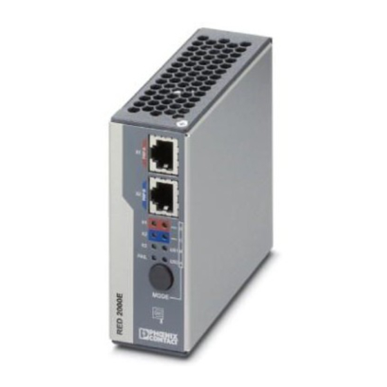
2. Légende ()
1 Contact d'alarme
2 Raccordement de tension d'alimentation
3 X3 : port SAN (Single Attached Node / équipement terminal)
4 Touche Mode pour le réglage de différents états préconfigurés
5 LED de diagnostic et d'état
6 X2 / PRP B : port réseau B
7 X1 / PRP A : port réseau A
3. Montage ()
Poser le module en plaçant le dispositif de guidage du profilé sur le bord supérieur du profilé et l'encliqueter
vers le bas.
4. Démontage ()
Insérer un outil adapté dans la languette (par ex. un tournevis pour vis à fente) et tirer celle-ci vers le bas (B1).
5. Dimensions du boîtier ()
6. Voyants de diagnostic et d'état ()
1 X1 / PRP A : port réseau A
2 X2 / PRP B : port réseau B
3 X3 : port SAN (Single Attached Node / équipement terminal)
4 FAIL : causes différentes
5 -D : diagnostic complémentaire pour port A
6 -C : diagnostic complémentaire pour port B
7 US1 : tension d'alimentation 1
8 US2 : tension d'alimentation 2
9 A (LED 8), B (LED 7), C (LED 6) et D (LED 5) en combinaison avec la touche de mode : indiquent le mode
sélectionné
7. Alimentation de l'appareil avec ne source de tension
Voir figure 6. ()
8. Alimentation redondante de l'appareil
Voir figure 7. ()
9. Raccordement du contact d'alarme
Voir fig. 8. ()
10. Caractéristiques techniques (tableau 1)
Tension de service DC
18 V DC à 58 V DC
Courant
200 mA (24 V DC) / 2701863 // 250 mA / 2701864
Puissance absorbée
4,8 W / 2701863 // 6 W / 2701864
Attribution d'adresse IP
Par défaut : BootP
Mot de passe
private
Contact d'alarme
48 V DC (18 ... 58 V DC) / 6 W
Article
Description
Description
Module de redondance Ethernet pour réseaux redondants avec protocole de
Ethernet redundancy module for redundant networks with the redundancy
redondance PRP et trois raccordements RJ45.
protocol PRP and three RJ45 connections.
Module de redondance Ethernet pour réseaux redondants avec protocole de
Ethernet redundancy module for redundant networks with the redundancy
redondance PRP
protocol PRP.
ENGLISH
Redundancy module
1. Safety notes
Caution: Installation only by qualified personnel
Installation, startup and maintenance of the product may only be performed by qualified specialist staff
who have been authorized for this by the system operator. An electrician is a person who, because of
their training, experience and instruction, and knowledge of relevant standards, can assess any required
operations and recognize any possible dangers. Specialist staff must read and understand this
documentation and comply with instructions. Observe the national regulations in force for the operation,
functional testing, repairs and maintenance of electronic devices.
Note: Electrostatic discharge
The devices contain components that can be damaged or destroyed by electrostatic discharge. When
handling the devices, observe the necessary safety precautions against electrostatic discharge (ESD)
in accordance with EN 61340-5-1 and EN 61340-5-2.
Caution: Requirement for power supply
The module is designed exclusively for operation with safety extra-low voltage (SELV) in accordance
with EN/IEC 60950-1 and VDE 0805.
Warning: This is a Class A product. In a domestic environment it may cause radio interference, in which
case the user may be required to take adequate measures.
Caution: Requirement for control cabinet/control box
This module snaps onto a DIN rail inside a control cabinet or control box. This control cabinet/box must
meet the requirements of EN 60950-1: 2006 with respect to fire protection enclosure.
Requirements for the current source
This device should only be operated with power supplies which meet the requirements of EN/IEC 60950-
1 for limited power sources. Otherwise the device is to be operated in a housing which meets the
requirements for fire protection enclosure according to EN/IEC 60950-1.
Caution: Functional grounding required
Mount the module on a grounded DIN rail. Grounding
of modules happens when they are snapped onto the DIN rail.
Caution: Requirements for functional grounding in non-DIN rail mounting
Ensure proper (functional) earthing of the device.
Caution: Requirement for mounting location
The prescribed mounting position is vertical on a horizontally mounted DIN rail. The vents may not be
covered so that air can circulate freely. A gap of 3 cm between the vents of the housing is recommended.
The product user manual is stored on the device as PDF and can be downloaded via web access under
"Help & Documentation".
2. Legend ()
1 Alarm contact
2 Connecting the supply voltage
3 X3: SAN-Port (Single Attached Node/termination device)
4 Mode button for setting various pre-configured states
5 Status and diagnostics LEDs
6 X2 / PRP B: Network port B
7 X1 / PRP A: Network port A
3. Mounting ()
Position the module with the DIN rail guide on the upper edge of the DIN rail, and snap it in with a downward
motion.
4. Removal ()
Use a suitable tool (e. g., flat-bladed screwdriver) to insert into the latch and pull it downwards (B1).
5. Housing dimensions ()
6. Status and diagnostics indicators ()
1 X1 / PRP A: Network port A
2 X2 / PRP B: Network port B
3 X3: SAN-Port (Single Attached Node/termination device)
4 FAIL: several causes
5 -D: additional diagnostics Port A
6 -C: additional diagnostics Port B
7 US1: Supply voltage 1
8 US2: Supply voltage 2
9 A (LED 8), B (LED 7), C (LED 6) and D (LED 5) in connection with the mode button: show the selected mode
7. Supplying the device using one voltage source
See figure 6. ()
8. Redundant device supply
See figure 7. ()
9. Connecting the alarm contact
See figure 8. ()
10. Technical data (table 1)
DC operating voltage
18 V DC to 58 V DC
Current
200 mA (24 V DC) / 2701863 // 250 mA / 2701864
Power consumption
4.8 W / 2701863 // 6 W / 2701864
IP address assignment
Default: BootP
Password
private
Alarm contact
48 V DC (18 ... 58 V DC) / 6 W
Article
Beschreibung
Ethernet-Redundanzmodul für redundante Netzwerke mit dem
Redundanzprotokoll PRP mit drei RJ45-Anschlüssen.
Ethernet-Redundanzmodul für redundante Netzwerke mit dem
Redundanzprotokoll PRP.
DEUTSCH
Redundanzmodul
1. Sicherheitshinweise
Achtung: Installation nur durch qualifiziertes Personal
Die Installation, Inbetriebnahme und Wartung des Produkts darf nur durch ausgebildetes Fachpersonal
erfolgen, das vom Anlagenbetreiber dazu autorisiert wurde. Elektrofachkraft ist, wer aufgrund seiner
fachlichen Ausbildung, Kenntnisse und Erfahrungen sowie Kenntnis der einschlägigen Normen die ihm
übertragenen Arbeiten beurteilen und mögliche Gefahren erkennen kann. Das Fachpersonal muss
diese Dokumentation gelesen und verstanden haben und die Anweisungen befolgen. Beachten Sie die
geltenden nationalen Vorschriften für Betrieb, Funktionsprüfung, Reparatur und Wartung von
elektronischen Geräten.
Achtung: Elektrostatische Entladung
Die Geräte enthalten Bauelemente, die durch elektrostatische Entladung beschädigt oder zerstört
werden können. Beachten Sie beim Umgang mit den Geräten die notwendigen Sicherheitsmaßnahmen
gegen elektrostatische Entladung (ESD) gemäß EN 61340-5-1 und EN 61340-5-2.
Achtung: Anforderung an die Spannungsversorgung
Das Modul ist ausschließlich für den Betrieb mit Sicherheitskleinspannung (SELV) nach EN/IEC 60950-
1 und VDE 0805 ausgelegt.
Warnung: Dies ist ein Klasse A-Erzeugnis. In Wohngebieten kann es zu Störungen des Funkempfanges
kommen. Der Betreiber soll entsprechende Schutzmaßnahmen treffen.
Achtung: Anforderung an den Schaltschrank/Schaltkasten
Dieses Modul wird innerhalb eines Schaltschranks oder –kastens auf eine Norm-Tragschiene
aufgerastet. Dieser Schaltschrank/-kasten muss den Anforderungen der EN 60950-1: 2006 bez. der
Brandschutzumhüllung genügen.
Anforderung an die Stromquelle
Das vorliegende Gerät darf nur mit Spannungsversorgungen betrieben werden, die die Vorgaben der
EN/IEC 60950-1 für Stromquellen begrenzter Leistung erfüllen. Andernfalls ist das Gerät in einem
Gehäuse zu betreiben, das den Anforderungen einer Brandschutzumhüllung nach EN/IEC 60950-1
genügt.
Achtung: Anforderung an die Funktionserdung
Montieren Sie das Modul auf einer geerdeten Tragschiene. Die Erdung
des Moduls erfolgt mit dem Aufrasten auf die Tragschiene.
Achtung: Anforderung an die Funktionserdung bei Nicht-Tragschienen-Montage
Sorgen Sie für eine bestimmungsgemäße (Funktions-) Erdung der Geräte.
Achtung: Anforderung an den Montageort
Die vorgeschriebene Einbaulage ist senkrecht auf einer horizontal montierten Tragschiene. Die
Lüftungsschlitze dürfen nicht bedeckt werden, so dass die Luft frei zirkulieren kann. Als Abstand zu den
Lüftungsschlitzen des Gehäuses werden mindestens 3 cm empfohlen.
Das Handbuch des Produktes befindet sich als PDF auf dem Gerät und kann über Web-Zugriff unter
„Help & Documentation" heruntergeladen werden.
2. Legende ()
1 Alarmkontakt
2 Anschluss der Versorgungsspannung
3 X3: SAN-Port (Single Attached Node / Endgerät)
4 Mode Taster zur Einstellung verschiedener vorkonfigurierter Zustände
5 Status- und Diagnose-LEDs
6 X2 / PRP B: Netzwerk-Port B
7 X1 / PRP A: Netzwerk-Port A
3. Montage ()
Setzen Sie das Modul mit der Tragschienenführung an die Oberkante der Tragschiene an und rasten Sie es
nach unten ein.
4. Demontage ()
Fassen Sie mit einem geeigneten Werkzeug (z. B. Schlitzschraubendreher) in die Lasche und ziehen Sie sie
nach unten (B1).
5. Gehäusemaße ()
6. Status- und Diagnoseanzeigen ()
1 X1 / PRP A: Netzwerk-Port A
2 X2 / PRP B: Netzwerk-Port B
3 X3: SAN-Port (Single Attached Node / Endgerät)
4 FAIL: verschiedene Ursachen
5 -D: ergänzende Diagnose zu Port A
6 -C: ergänzende Diagnose zu Port B
7 US1: Versorgungsspannung 1
8 US2: Versorgungsspannung 2
9 A (LED 8), B (LED 7), C (LED 6) und D (LED 5) in Verbindung mit dem Mode-Button: zeigen den gewählten
Mode
7. Versorgung des Gerätes mit einer Spannungsquelle
Siehe Bild 6. ()
8. Redundante Versorgung des Gerätes
Siehe Bild 7. ()
9. Anschluss des Alarmkontaktes
Siehe Bild 8. ()
10. Technische Daten (Tabelle 1)
Betriebsspannung DC
18 V DC bis 58 V DC
Strom
200 mA (24 V DC) / 2701863 // 250 mA / 2701864
Leistungsaufnahme
4,8 W / 2701863 // 6 W / 2701864
IP-Adress-Vergabe
Default: BootP
Passwort
private
Alarmkontakt
48 V DC (18 ... 58 V DC) / 6 W
Artikel
FL RED 2003E PRP
FL RED 2001E PRP 2LC
PHOENIX CONTACT GmbH & Co. KG
Flachsmarktstraße 8, 32825 Blomberg, Germany
Fax +49-(0)5235-341200, Phone +49-(0)5235-300
phoenixcontact.com
DE
Einbauanweisung für den Elektroinstallateur
EN
Installation notes for electricians
FR
Instructions d'installation pour l'électricien
FL RED 2003E PRP
FL RED 2001E PRP 2LC
X1
X2
X1
X2
X3
D
FA
C
IL
US
1
B
US
2
A
M O
D E
X3
3
2
1
B
A
A1
A2
40
109
X1
X2
X1
D
X2
C
X3
US1
B
FAIL
US2
A
MODE
X3
115
X4
24 V DC
X4
X5
24 V DC
2701863
2701864
© PHOENIX CONTACT 2016
PNR 105651 - 01
2016-09-14
2701863
2701864
7
6
5
4
B2
B1
in
out
Werbung

Verwandte Anleitungen für Phoenix Contact FL RED 2003E PRP


Inhaltszusammenfassung für Phoenix Contact FL RED 2003E PRP
- Seite 1 PHOENIX CONTACT GmbH & Co. KG FRANÇAIS ENGLISH DEUTSCH Flachsmarktstraße 8, 32825 Blomberg, Germany Module pour redondance Redundancy module Redundanzmodul Fax +49-(0)5235-341200, Phone +49-(0)5235-300 phoenixcontact.com 2016-09-14 1. Consignes de sécurité 1. Safety notes 1. Sicherheitshinweise Einbauanweisung für den Elektroinstallateur Important : seul du personnel dûment qualifié est autorisé à procéder à l'installation.
- Seite 2 PHOENIX CONTACT GmbH & Co. KG ESPAÑOL PORTUGUÊS ITALIANO Flachsmarktstraße 8, 32825 Blomberg, Germany Módulo de redundancia Módulo de redundância Modulo di ridondanza Fax +49-(0)5235-341200, Phone +49-(0)5235-300 phoenixcontact.com 2016-09-14 1. Advertencias de seguridad 1. Instruções de segurança 1. Indicazioni di sicurezza Istruzioni di montaggio per l'elettricista installatore IMPORTANTE: instalación solamente a cargo de personal cualificado...
- Seite 3 中文 PHOENIX CONTACT GmbH & Co. KG РУССКИЙ TÜRKÇE Flachsmarktstraße 8, 32825 Blomberg, Germany 冗余模块 Резервные модули Yedekleme modülü Fax +49-(0)5235-341200, Phone +49-(0)5235-300 phoenixcontact.com 2016-09-14 1. 安全提示 1. Правила техники безопасности 1. Güvenlik notları Elektrik personeli için montaj talimatı 小心:仅允许专业人员进行安装...
- Seite 4 PHOENIX CONTACT GmbH & Co. KG POLSKI ENGLISH DEUTSCH Flachsmarktstraße 8, 32825 Blomberg, Germany Moduł redundantny Redundancy module Redundanzmodul Fax +49-(0)5235-341200, Phone +49-(0)5235-300 phoenixcontact.com 2016-09-14 1. Wskazówki dotyczące bezpieczeństwa 1. Safety notes 1. Sicherheitshinweise Einbauanweisung für den Elektroinstallateur Uwaga: instalacja tylko przez wykwalifikowany personel...