Herunterladen Inhalt Inhalt Diese Seite drucken
Inhaltsverzeichnis

Werbung

Verfügbare Sprachen

Verfügbare Sprachen

Bedienungsanleitung
Stromzange
Best.-Nr. 2274366
Operating Instructions
Clamp meter
Item No. 2274366
Notice d'emploi
Pince ampèremétrique
N° de commande 2274366
Gebruiksaanwijzing
Stroomtang
Bestelnr. 2274366
Seite 2 - 31
Page 32 - 61
Page 62 - 91
Pagina 92 - 121

Werbung

Inhaltsverzeichnis
loading

Inhaltszusammenfassung für VOLTCRAFT 2274366

  • Seite 1 Bedienungsanleitung Stromzange Best.-Nr. 2274366 Seite 2 - 31 Operating Instructions Clamp meter Item No. 2274366 Page 32 - 61 Notice d’emploi Pince ampèremétrique N° de commande 2274366 Page 62 - 91 Gebruiksaanwijzing Stroomtang Bestelnr. 2274366 Pagina 92 - 121...
  • Seite 2: Inhaltsverzeichnis

    Inhaltsverzeichnis Seite 1. Einführung ...........................4 2. Symbol-Erklärung ........................4 a) Symbole in dieser Bedienungsanleitung ..............4 b) Symbole am Produkt ....................5 3. Bestimmungsgemäße Verwendung ..................6 4. Lieferumfang ........................7 5. Merkmale und Funktionen ....................7 6. Sicherheitshinweise ......................8 a) Allgemein ........................8 b) Angeschlossene Geräte ....................9 c) Batterien ........................9 d) Personen und Produkt ....................9 7.
  • Seite 3 Durchgangsprüfung ....................22 g) Diodentest ........................23 h) Kapazitätsmessung ....................23 Berührungslose Wechselspannungsdetektion „NCV“ ..........24 10. Zusatzfunktionen .......................25 a) Automatische Abschaltung ..................25 b) Beleuchtung .......................26 c) HOLD-Funktion ......................26 d) Taschenlampenfunktion ....................26 11. Wartung ..........................27 12. Pflege und Reinigung ......................27 13. Entsorgung ........................28 a) Produkt ........................28 b) Batterien ........................28 14.
  • Seite 4: Einführung

    1. Einführung Sehr geehrte Kundin, sehr geehrter Kunde, wir bedanken uns für den Kauf dieses Produkts. Dieses Produkt entspricht den gesetzlichen, nationalen und europäischen Anforderungen. Um diesen Zustand zu erhalten und einen gefahrlosen Betrieb sicherzustellen, müssen Sie als Anwender diese Bedienungsanleitung beachten! Diese Bedienungsanleitung gehört zu diesem Produkt.
  • Seite 5: Symbole Am Produkt

    b) Symbole am Produkt Symbol Bedeutung Dieses Symbol zeigt an, dass dieses Produkt nach Schutzklasse II aufge- baut ist. Es besitzt eine verstärkte oder doppelte Isolierung zwischen Netz- stromkreis und Ausgangsspannung. Erdpotential Das Symbol mit dem Ausrufezeichen im Dreieck wird verwendet, wenn Gefahr für Ihre Gesundheit besteht, z.B.
  • Seite 6: Bestimmungsgemäße Verwendung

    3. Bestimmungsgemäße Verwendung Das Produkt dient zum Messen und Anzeigen der elektrischen Größen im Bereich der Über- spannungskategorie CAT II bis max. 1000 V und CAT III bis max. 600 V gegen Erdpotential, gemäß EN 61010-1, EN 61010-2-032, EN 61010-2-033 und allen niedrigeren Kategorien. - Messen von Gleich- und Wechselspannung bis max.
  • Seite 7: Lieferumfang

    Alle enthaltenen Firmennamen und Produktbezeichnungen sind Warenzeichen der jeweiligen Inhaber. Alle Rechte vorbehalten. 4. Lieferumfang • Stromzange • Prüfleiter (1 Paar) • 2 x AA Batterie • Bedienungsanleitung • Tragetasche Aktuelle Bedienungsanleitungen Laden Sie aktuelle Bedienungsanleitungen über den Link www.conrad.com/downloads herunter oder scannen Sie den abgebildeten QR-Code. Befolgen Sie die Anweisungen auf der Webseite. 5.
  • Seite 8: Sicherheitshinweise

    6. Sicherheitshinweise Lesen Sie sich die Bedienungsanleitung aufmerksam durch und beachten Sie insbesondere die Sicherheitshinweise. Falls Sie die Sicherheitshinweise und die Angaben zur sachgemäßen Handhabung in dieser Bedienungsanleitung nicht befolgen, übernehmen wir für dadurch resultierende Personen-/ Sachschäden keine Haftung. Außerdem erlischt in solchen Fällen die Gewährleistung/Garantie.
  • Seite 9: Angeschlossene Geräte

    b) Angeschlossene Geräte • Beachten Sie auch die Sicherheitshinweise und Bedienungsanleitungen der übri- gen Geräte, an die das Produkt angeschlossen wird. c) Batterien • Achten Sie beim Einlegen der Batterien auf die richtige Polung. • Entfernen Sie die Batterien, wenn Sie das Gerät längere Zeit nicht verwenden, um Beschädigungen durch Auslaufen zu vermeiden.
  • Seite 10 • Verwenden Sie zum Messen nur die mitgelieferten Prüfleiter, da diese auf die Spezifikationen des Messgerätes abgestimmt sind. • In Schulen und Ausbildungseinrichtungen, Hobby- und Selbsthilfewerkstätten ist der Umgang mit Messgeräten durch geschultes Personal verantwortlich zu über- wachen. • In gewerblichen Einrichtungen sind die Unfallverhütungsvorschriften des Ver- bandes der gewerblichen Berufsgenossenschaften für elektrische Anlagen und Betriebsmittel zu beachten.
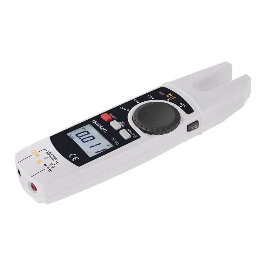
  • Seite 11: Bedienelemente Und Symbole

    • Beachten Sie bei jeder Messung die Beschreibung der Abbildungen in jedem Ka- pitel. Eine falsche Messung könnte das Produkt zerstören. • Entfernen Sie vor dem Anschluss der Prüfleiter die Staubschutzkappen von den Anschlusssteckern der Prüfleiter. Montieren Sie diese stets nach jeder Messung, um eine Verschmutzung der Kontakte zu vermeiden. • Beachten Sie auch die Sicherheitshinweise in den einzelnen Kapiteln. •...
  • Seite 12: Symbole Im Lc-Display

    b) Symbole im LC-Display Symbol Erklärung Ω Ohm (Einheit des elektrischen Widerstandes) kΩ, MΩ Kilo-Ohm (exp.3), Mega-Ohm (exp.6) Hertz (Einheit der elektrischen Frequenz) Milli-Volt (exp.–3) mA, μA Milli-Ampere (exp.–3), Micro-Ampere (exp.–6) Nano-Farad (exp.–9; Einheit der elektrischen Kapazität) μF Mikro-Farad (exp.–6) Milli-Farad (exp.-3) Volt (Einheit der elektrischen Spannung) Ampere (Einheit der elektrischen Stromstärke) Messwert-Anzeige...
  • Seite 13: Einlegen/Wechseln Der Batterien

    Symbol Erklärung Blitzsymbol zur Spannungsmessung Anzeige des Vorzeichens des Messwerts Gleichspannung/-strom Wechselspannung/-strom HOLD-Funktion ist aktiv, wenn das Symbol angezeigt wird Relativmessung ist eingestellt Nullstellung 8. Einlegen/Wechseln der Batterien a) Batterien einlegen Bei Anlieferung des Produktes sind üblicherweise keine Batterien eingesetzt. Der Ge- brauch von Akkus ist wegen der niedrigeren Spannung nicht empfohlen.
  • Seite 14: Batterien Wechseln

    Abb. 1 b) Batterien wechseln Ein Batteriewechsel ist erforderlich, wenn im LC-Display (5) das Symbol (D) aufleuchtet oder die Hintergrundbeleuchtung nur noch schwach oder gar nicht mehr leuchtet. Ersetzen Sie die Batterien möglichst bald wie im Abschnitt „a) Batterien einlegen“ beschrieben. Leuchtet nach dem Einschalten nur das Symbol auf, ersetzen Sie sofort die Batterien.
  • Seite 15: Ein-/Ausschalten / Messfunktion Wählen

    Messungen in Stromkreisen >33 V/AC und >42 V/DC dürfen nur von Fachkräften und eingewiesenen Personen durchgeführt werden, die mit den einschlägigen Vorschriften und den daraus resultierenden Gefahren vertraut sind. Beachten Sie die erforderlichen Sicherheitshinweise, Vorschriften und Schutzmaßnahmen zur Eigensicherung. Die Messwerte werden in der LC-Display (5) der Stromzange dargestellt. Die Polarität wird bei negativem Messwert automatisch mit Vorzeichen (-) dargestellt.
  • Seite 16: Relative Messung

    b) Relative Messung Sie können Messwerte absolut messen (normaler Messmodus) oder einen Wert in Beziehung zum vorhergehenden messen. • Um einen aktuell erfassten Messwert als Ausgangswert (Nullwert) zu übernehmen, drücken Sie im normalen Messmodus während einer Messung die Taste REL ZER (8). Die Displaya- (P) werden im LC-Display (5) angezeigt.
  • Seite 17 Messen von Wechselstrom A • Schalten Sie das Produkt am Drehschalter (3) ein und wählen den Messbereich A . Das Produkt ist im Messbereich für Wechselstrom und im LC-Display (5) erscheint „AC“ und „A“. • Der Wechselstrom-Messbereich wird vom Messgerät automatisch gewählt.
  • Seite 18 • Nach einem erfolgreichem Nullabgleich, führen Sie den einzelnen Stromleiter, der gemessen werden soll in die Stromzange ein. Positionieren Sie den Stromleiter entlang der beiden Richtungslinien am unteren Ende der U-förmigen Stromzange. • Der gemessene Strom wird im LC-Display angezeigt. •...
  • Seite 19: D) Spannungsmessung „V

    d) Spannungsmessung „V“ Messung von Wechselspannungen „AC“ (V • Schalten Sie das Produkt am Drehschalter (3) ein und wählen den Messbereich V . In der Anzeige erscheint „AC“ und „V“. • Stecken rote Messleitung V-Messbuchse (6), die schwarze Messleitung in die COM-Messbuchse (7).
  • Seite 20 Messung von Gleichspannungen „DC“ (V • Schalten Sie das Produkt am Drehschalter (3) ein und wählen den Messbereich V . Drücken Sie die Taste SELECT (9), um den Gleichstrommessbereich zu wählen. In der Anzeige erscheinen „DC“ und „V“ • Stecken rote Messleitung V-Messbuchse (6), die schwarze Messleitung in die...
  • Seite 21: Widerstandsmessung

    e) Widerstandsmessung Vergewissern Sie sich, dass alle zu messenden Schaltungsteile, Schaltungen und Bauelemente, z. B. Kondensatoren sowie andere Messobjekte unbedingt spannungslos und entladen sind. • Schalten Sie das Produkt am Drehschalter (3) ein und wählen den Messbereich . In der Anzeige erscheinen „Ω“ und „V“.
  • Seite 22: Durchgangsprüfung

    f) Durchgangsprüfung Vergewissern Sie sich, dass alle zu messenden Schaltungsteile, Schaltungen und Bauelemente sowie andere Messobjekte, z.B. Kondensatoren unbedingt spannungslos und entladen sind. • Schalten Sie das Produkt am Drehschalter (3) ein und wählen den Messbereich • Drücken Sie die Taste SELECT (9), um den Messbereich für die Durchgangsprüfung zu wählen.
  • Seite 23: Diodentest

    g) Diodentest Vergewissern Sie sich, dass alle zu messenden Schaltungsteile, Schaltungen und Bauelemente sowie andere Messobjekte, z.B. Kondensatoren, unbedingt spannungslos und entladen sind. • Schalten Sie das Produkt am Drehschalter (3) ein und wählen den Messbereich • Drücken Sie die Taste SELECT (9), um den Messbereich für den Diodentest zu wählen.
  • Seite 24: I) Berührungslose Wechselspannungsdetektion „Ncv

    • Schalten Sie das Produkt am Drehschalter (3) ein und wählen den Messbereich • Drücken Sie die Taste SELECT (9), um den Messbereich für den Kapazitätsmessung wählen. Im LC-Display erscheint • Stecken Sie die rote Messleitung in die V-Messbuchse (6), die schwarze Messleitung in die COM -Messbuchse (7).
  • Seite 25: Zusatzfunktionen

    Gehen Sie wie folgt vor: • Schalten Sie das Produkt am Drehschalter (3) ein und stellen Sie den Drehschalter (3) auf Position NCV. • Führen Sie den Magnetfeld-(NCV)-Sensor an der rechten Seite der Stromzange so nah wie möglich an einen Leiter. Der Abstand sollte bis ca.10 mm betragen.
  • Seite 26: Beleuchtung

    b) Beleuchtung • Für eine bessere Ablesbarkeit des LC-Displays (5) ist die Stromzange mit einer Hintergrundbeleuchtung ausgestattet. • Schalten Sie die Hintergrundbeleuchtung ein, indem Sie die Taste HOLD/ (4) drücken und für ca. 2 Sekunden festhalten, um in die Beleuchtung mit niedriger Intensität zu schalten. •...
  • Seite 27: Wartung

    11. Wartung • Die Stromzange ist bis auf eine gelegentliche Reinigung und dem Batteriewechsel wartungsfrei. • Es sind keinerlei für Sie zu wartende Bestandteile im Inneren des Produkts, öffnen Sie es deshalb niemals (bis auf die in dieser Bedienungsanleitung beschriebene Vorgehensweise beim Einlegen/Wechseln der Batterien).
  • Seite 28: Entsorgung

    13. Entsorgung a) Produkt Elektronische Geräte sind Wertstoffe und gehören nicht in den Hausmüll. Entsorgen Sie das Produkt am Ende seiner Lebensdauer gemäß den geltenden gesetzlichen Bestimmungen. Entnehmen Sie evtl. eingelegte Batterien und entsorgen Sie diese getrennt vom Produkt. b) Batterien Sie als Endverbraucher sind gesetzlich (Batterieverordnung) zur Rückgabe aller gebrauchten Batterien verpflichtet; eine Entsorgung über den Hausmüll ist untersagt.
  • Seite 29: B) Messtoleranzen

    Betriebsbedingungen ...... 0 bis 30 °C; <80 % +30 bis +40 °C, <75 % +40 bis +50 °C, <45 % relative Luftfeuchte (nicht kondensierend) Lagerbedingungen ......-20 bis +60 °C, <80% Betriebshöhe ........max. 2000 m Abmessungen (B x H x T) ....ca. 209 x 53 x 35 mm Gewicht ...........
  • Seite 30 Gleichspannung Bereich Auflösung Genauigkeit 6,0 V 0,001 V ± (0,8 % + 3) 60,0 V 0,01 V ± (0,8 % + 3) 600,0 V 0,1 V ± (0,8 % + 3) 1000,0 V ± (1 % + 5) Überlastschutz: 1000 V/DC, 200 A; Impedanz: >10 MΩ Widerstand Bereich Auflösung Genauigkeit...
  • Seite 31 Diodentest Bereich Auflösung Genauigkeit 6,00 V 0,001 V 0,5 - 0,8 V Überlastschutz: 1000 V/DC,750 V/AC, 200 A, Prüfspannung ca. 3,3 V Akustische Durchgangsprüfung Bereich Auflösung Genauigkeit 600,00 Ω 0,1 Ω <10 Ω Dauerton <10 Ω Dauerton >100 Ω (kein Ton) Überlastschutz: 1000 V/DC,750 V/AC, 200 A, Prüfspannung ca. 1,2 V Berührungslose Spannungsmessung Bereich Abstand...
  • Seite 32 Table of contents Page 1. Introduction ........................34 2. Description of symbols ......................34 a) Symbols in these operating instructions ..............34 b) Symbols on the product ....................35 3. Intended use ........................36 4. Package contents ......................37 5. Features and functions ......................37 6. Safety information ......................38 a) General information ....................38 b) Connected devices .....................38 c) Batteries ........................39...
  • Seite 33 Continuity testing ......................52 g) Diode testing ......................53 h) Capacitance measurement ..................53 Non-contact AC voltage detection (NCV) ..............54 10. Additional functions ......................55 a) Automatic shut-off ......................55 b) Backlight ........................56 c) ‘HOLD’ function ......................56 d) Torch function ......................56 11. Maintenance ........................57 12. Care and cleaning ......................57 13.
  • Seite 34: Introduction

    1. Introduction Dear customer Thank you for purchasing this product. This product complies with statutory, national and European regulations. To ensure that the product remains in this state and to guarantee safe operation, always follow the information in these operating instructions. These operating instructions are part of this product.
  • Seite 35: Symbols On The Product

    b) Symbols on the product Symbol Meaning This symbol indicates that this product is built according to protection class II. It is equipped with reinforced or dual insulation between the mains circuit and the output voltage. Earth potential The symbol with the exclamation mark in the triangle is used if there is a risk to your health, e.g.
  • Seite 36: Intended Use

    3. Intended use The product is intended for measuring and displaying electrical parameters in the range of the overvoltage categories CAT II to max. 1000 V and CAT III to max. 600 V against earth potential, in accordance with EN 61010-1, EN 61010-2-032, EN 61010-2-033 and all lower categories. - Measurement of direct and alternating voltages up to 1,000 V/DC, 750 V/AC - Measurement of direct and alternating currents up to a maximum of 200 A - Measurement of resistance...
  • Seite 37: Package Contents

    4. Package contents • Current clamp • Test lead (1 pair) • 2x AA battery • Operating instructions • Carrying case Up-to-date operating instructions Download the up-to-date operating instructions at www.conrad.com/downloads or scan the QR code shown. Follow the instructions on the website. 5.
  • Seite 38: Safety Information

    6. Safety information Read the operating instructions carefully and the safety information in particular. If you do not follow the safety information and information on proper handling in these operating instructions, we will assume no liability for any resulting personal injury or damage to property. Such cases will invalidate the warranty/guarantee.
  • Seite 39: C) Batteries

    c) Batteries • Check that the batteries are inserted with the correct polarity. • To prevent battery leakage, remove the batteries if you do not plan to use the product for an extended period. Leaking or damaged batteries may cause acid burns if they come into contact with your skin.
  • Seite 40 • Check the measuring device and its test leads for damage before each measure- ment. • Set the measuring device to the desired unit before each measurement. An incor- rect measurement may destroy the product! • The voltage between the connection points must not exceed the specified voltage. •...
  • Seite 41: Controls And Symbols

    7. Controls and symbols a) Current clamp Current clamp Torch button Rotary switch for selecting the measuring mode HOLD/ button LC display V measuring socket (  Ω) COM measuring socket REL ZERO button SELECT button 10 Battery compartment (back) 11 NCV signal display...
  • Seite 42: B) Symbols On Lc Display

    b) Symbols on LC display Symbol Meaning Ω Ohm (unit of electrical resistance) kΩ, MΩ Kiloohm (exp. 3), megaohm (exp. 6) Hertz (unit of electrical frequency) Millivolt (exp. –3) mA, μA Milliampere (exp. –3), micro-ampere (exp. –6) Nanofarad (exp. –9; unit of electrical capacitance) μF Microfarad (exp.
  • Seite 43: Inserting/Changing The Batteries

    Symbol Meaning Lightning icon for voltage measuring Displays the sign of the measured value Direct voltage/current Alternating voltage/current HOLD function is active when the symbol is displayed Relative measurement is set Zero reset 8. Inserting/changing the batteries a) Inserting the batteries Batteries are not normally inserted when the product is delivered to you.
  • Seite 44: Replacing The Batteries

    Fig. 1 b) Replacing the batteries The batteries need to be replaced if the symbol (D) lights up on the LC display (5) or the back- light is dim or does not come on at all. Replace the batteries as soon as possible as described in ‘a) Inserting the batteries’.
  • Seite 45: A) Switching On/Off And Selecting The Measuring Function

    Measurements in circuits rated at >33 V/AC and >42 V/DC may only be carried out  by  qualified  and  trained  personnel  who  are  familiar  with  the  relevant  regulations and the associated hazards. Pay attention to the requisite safety information, regulations and protective measures for your own safety.
  • Seite 46: Relative Measurement

    b) Relative measurement You can measure values absolutely (normal measuring mode) or measure a value in relation to the previous measurement. • To accept a currently recorded measured value as the output value (zero value), press the REL ZERO button (8) during a measurement in normal measuring mode. The display (P) are shown on the LC display (5).
  • Seite 47 AC current measurement A • Switch the product on at the rotary switch (3) and select measurement range A . The product is in the measurement range for alternating current and the LC display (5) shows ‘AC’ and ‘A’. • The measuring device automatically selects the AC measurement range.
  • Seite 48 • After a successful zero adjustment, route the individual conductor that is to be measured into the current clamp. Position the conductor along the two direction lines at the bottom end of the U-shaped current clamp. • The measured current is shown on the LC display. •...
  • Seite 49: D) Voltage Measurement 'V

    d) Voltage measurement ‘V’ AC voltage measurement (V • Switch the product on at the rotary switch (3) and select the measurement range V . ‘AC’ and ‘V’ appear on the display. • Insert the red test lead into the V socket (6) and the black test lead into the COM socket (7).
  • Seite 50 DC voltage measurement (V • Switch the product on at the rotary switch (3) and select the measurement range V . Press the SELECT button (9) to select the DC measurement range. ‘DC’ and ‘V’ appear on the display. • Insert the red test lead into the V socket (6) and the black test lead into the COM socket (7).
  • Seite 51: Resistance Measurement

    e) Resistance measurement Ensure that all objects that you wish to measure (including circuit components, circuits and component parts as well as other measured objects such as capacitors) are disconnected and discharged. • Switch the product on at the rotary switch (3) and select the measurement range .
  • Seite 52: Continuity Testing

    f) Continuity testing Ensure that all objects that you wish to measure (including circuit components, circuits and component parts as well as other measured objects, e.g. capacitors) are disconnected and discharged. • Switch the product on at the rotary switch (3) and select the measurement range •...
  • Seite 53: Diode Testing

    g) Diode testing Ensure that all objects that you wish to measure (including circuit components, circuits and component parts as well as other measured objects, e.g. capacitors) are disconnected and discharged. • Switch the product on at the rotary switch (3) and select the measurement range •...
  • Seite 54: I) Non-Contact Ac Voltage Detection (Ncv)

    • Switch the product on at the rotary switch (3) and select the measurement range • Press the SELECT button (9) to select the measurement range for the capacitance measurement appears on the LC display. • Insert the red test lead into the V socket (6) and the black test lead into the COM socket (7).
  • Seite 55: Additional Functions

    • Switch the product on at the rotary switch (3) and set the rotary switch (3) to position NCV. • Guide the magnetic field (NCV) sensor on the right- hand side of the current clamp, as close as possible to a conductor. The distance should be up to approx. 10 mm.
  • Seite 56: Backlight

    b) Backlight • The current clamp features a backlight so that the LC display (5) can be read more easily. • Switch on the backlight by pressing the HOLD/ button (4) and holding it for approx. 2 seconds to switch to low intensity lighting. •...
  • Seite 57: Maintenance

    11. Maintenance • The current clamp does not require maintenance apart from occasional cleaning and changing the battery. • Under no circumstances should you service any of the components in the interior of the device. For this reason, never open the product (except for inserting/changing the batteries as described in these operating instructions).
  • Seite 58: Disposal

    13. Disposal a) Product Electronic devices are recyclable waste and must not be placed in household waste. At the end of its service life, dispose of the product according to the relevant statutory regulations. Remove any inserted batteries and dispose of them separately from the product.
  • Seite 59: Measurement Tolerances

    Operating conditions ....... 0 to 30 °C; <80 % +30 to +40 °C, <75 % +40 to +50 °C, <45 % relative humidity (non-condensing) Storage conditions ......-20 to +60 °C, <80 % Operating altitude ......max. 2000 m Dimensions (W x H x D) ....approx. 209 x 53 x 35 mm Weight ..........
  • Seite 60 DC voltage Range Resolution Accuracy 6.0 V 0.001 V ± (0.8 % + 3) 60.0 V 0.01 V ± (0.8 % + 3) 600.0 V 0.1 V ± (0.8 % + 3) 1000.0 V ± (1 % + 5) Overload protection: 1000 V/DC, 200 A; Impedance: >10 MΩ Resistance Range Resolution...
  • Seite 61 Diode testing Range Resolution Accuracy 6.00 V 0.001 V 0.5 - 0.8 V Overload protection: 1000 V/DC,750 V/AC, 200 A, test voltage approx. 3.3 V Acoustic continuity test Range Resolution Accuracy 600.00 Ω 0.1 Ω < 10 Ω continuous <10 Ω continuous tone tone >100 Ω...
  • Seite 62 Table des matières Page 1. Introduction ........................64 2. Explication des symboles ....................64 a) Symboles dans ce mode d'emploi ................64 b) Symboles sur le produit ....................65 3. Utilisation prévue .......................66 4. Contenu d’emballage ......................67 5. Caractéristiques et fonctions .....................67 6. Consignes de sécurité .......................68 a) Généralités .........................68 b) Appareils connectés ....................69 c) Piles..........................69...
  • Seite 63 Contrôle de continuité ....................82 g) Test de diodes ......................83 h) Mesure de la capacité ....................83 Détection de tension alternative sans contact (NCV) ..........84 10. Fonctions supplémentaires ....................85 a) Mise hors tension automatique ..................85 b) Éclairage ........................86 c) Fonction HOLD ......................86 d) Fonction lampe de poche ...................86 11.
  • Seite 64: Introduction

    1. Introduction Chers clients, Nous vous remercions d’avoir choisi ce produit. Ce produit est conforme aux exigences des normes européennes et nationales en vigueur. Afin de maintenir l’appareil en bon état et d’en assurer un fonctionnement sans danger, l’utilisa- teur doit impérativement respecter ce mode d’emploi ! Ce mode d’emploi fait partie intégrante du produit.
  • Seite 65: Symboles Sur Le Produit

    b) Symboles sur le produit Symbole Signification Ce symbole indique que cet appareil est conforme à la classe de protection II. Il possède une isolation double ou renforcée entre le réseau d’alimentation et la tension de sortie. Potentiel de terre Le symbole avec le point d'exclamation placé...
  • Seite 66: Utilisation Prévue

    3. Utilisation prévue Ce produit sert à mesurer et afficher les valeurs électriques appartenant aux catégories de surtension CAT II jusqu’à 1000 V max. et CAT III jusqu’à 600 V max., par rapport au poten- tiel terrestre conformément aux normes EN 61010-1, EN 61010-2-032, EN 61010-2-033, ou à toutes les catégories inférieures.
  • Seite 67: Contenu D'emballage

    Pour des raisons de sécurité et d’homologation, toute transformation et/ou modification du produit est interdite. Si vous utilisez le produit à des fins autres que celles décrites précédem- ment, vous risquez de l’endommager. Par ailleurs, une utilisation incorrecte peut être source de dangers tels que les courts-circuits, les incendies, l'électrocution.
  • Seite 68: Consignes De Sécurité

    6. Consignes de sécurité Lisez attentivement le mode d’emploi dans son intégralité, en étant particulièrement attentif aux consignes de sécurité. Nous déclinons toute responsabilité en cas de dommage corporel ou matériel résultant du non- respect des consignes de sécurité et des instructions d’utilisation de ce mode d’emploi.
  • Seite 69: Appareils Connectés

    b) Appareils connectés • Respectez également les consignes de sécurité et le mode d’emploi des autres appareils connectés au produit. c) Piles • Respectez la polarité lors de l’insertion des piles. • Retirez les piles si vous ne comptez pas utiliser l’appareil pendant une période prolongée afin d’éviter des dommages dus à...
  • Seite 70 • N'utilisez pour la mesure que les conducteurs de test fournis car ils sont conformes aux caractéristiques de l'instrument de mesure. • Dans les écoles, les centres de formation, les ateliers de loisirs et de réinsertion, la manipulation d’un appareil de mesure doit se faire sous la surveillance d’un personnel responsable, spécialement formé...
  • Seite 71: Commandes Et Symboles

    • Lors de chaque mesure, observez la description des illustrations à chaque cha- pitre. Une erreur dans la mesure pourrait détruire le produit. • Avant de raccorder les conducteurs de test, retirez les capuchons de protection contre la poussière sur les fiches de raccordement des conducteurs de test. Ré- installez toujours ceux-ci après chaque mesure, afin d'éviter de salir les contacts.
  • Seite 72: B) Symboles À L'écran À Cristaux Liquides

    b) Symboles à l'écran à cristaux liquides N° Symbole Explication Ω Ohm (unité de résistance électrique) kΩ, MΩ Kilo-ohm (exp.3), mégaohm (exp.6) Hertz (unité de fréquence électrique) Millivolt (exp.–3) mA, μA Milliampère (exp.-3), microampère (exp.-6) Nano Farad (exp.-9 ; unité de capacité électrique) μF Micro Farad (exp.-6) Milli Farad (exp.-3)
  • Seite 73: Insertion/Remplacement Des Piles

    N° Symbole Explication Symbole d'éclair pour la mesure de la tension Affichage du signe de la valeur mesurée Tension continue/courant continu Tension alternée/courant alternatif La fonction HOLD est active lorsque le symbole est affiché La mesure relative est réglée Mise à zéro 8.
  • Seite 74: Remplacement Des Piles

    Fig. 1 b) Remplacement des piles Un remplacement des piles est nécessaire si le symbole (D) s'allume sur l'écran LCD (5) ou si le rétroéclairage est encore faible ou s'il n'est plus allumé. Changez les piles dans les plus brefs délais, voir section «...
  • Seite 75: A) Sélectionner Marche/Arrêt/Fonction De Mesure

    Les relevés de mesure sur les circuits électriques >33 V/CA et >42 V/CC doivent impérativement être effectués par des professionnels ou des personnes initiées, qui connaissent les consignes de sécurité et qui sont informés des dangers qui en résultent. Respectez les consignes de sécurité, les règlements et les mesures de protection applicables afin de garantir votre sécurité.
  • Seite 76: B) Mesure Relative

    b) Mesure relative Vous pouvez mesurer des valeurs de mesure absolues (mode de mesure normal) ou une valeur par rapport à la valeur précédente. • Pour accepter une valeur de mesure actuellement enregistrée comme valeur de sortie (va- leur zéro), appuyez sur la touche REL ZER (8) en mode de mesure normal pendant une (P) sont affichés sur mesure.
  • Seite 77 Mesure du courant alternatif A • Allumez l'appareil avec le bouton rotatif (3), et sélectionnez la gamme de mesure A . Le produit est dans la gamme de mesure pour le courant alternatif et sur l'écran LCD (5), « AC » et « A » apparaissent. •...
  • Seite 78 • Chaque pression brève sur la touche REL ZERO déclenche une nouvelle remise à zéro. Pour désactiver cette fonction, appuyez et maintenez la touche REL ZERO pendant env. 2 secondes. Le symbole « ZERO » disparaît. Vous vous trouvez à nouveau dans le mode de mesure normal sans égalisation à...
  • Seite 79: D) Mesure De La Tension « V

    d) Mesure de la tension « V » Mesure de tensions alternatives « CA » (V • Allumez l'appareil avec le bouton rotatif, et sélectionnez la plage de mesure V . L'écran indique « AC » et « V ». •...
  • Seite 80 Mesure de tensions continues « CC » (V • Allumez l'appareil avec le bouton rotatif (3), et sélectionnez la plage de mesure V . Appuyez sur la touche SELECT (9) pour sélectionner la gamme de mesure de courant continu. Sur l'écran d'affichage apparaissent «...
  • Seite 81: Mesure De La Résistance

    e) Mesure de la résistance Assurez-vous que tous les éléments du circuit, tous les circuits, tous les composants, tels que les condensateurs ainsi que les autres objets à mesurer soient impérativement hors tension et déchargés. • Allumez l'appareil avec le bouton rotatif (3), et sélectionnez la gamme de mesure .
  • Seite 82: Contrôle De Continuité

    f) Contrôle de continuité Assurez-vous que tous les éléments du circuit, tous les circuits, tous les composants ainsi que les autres objets à mesurer, tels que les condensateurs soient impérativement hors tension et déchargés. • Allumez l'appareil avec le bouton rotatif (3), et sélectionnez la gamme de mesure •...
  • Seite 83: Test De Diodes

    g) Test de diodes Assurez-vous que tous les éléments du circuit, tous les circuits, tous les composants ainsi que les autres objets à mesurer, tels que les condensateurs soient impérativement hors tension et déchargés. • Allumez l'appareil avec le bouton rotatif (3), et sélectionnez la gamme de mesure •...
  • Seite 84: I) Détection De Tension Alternative Sans Contact (Ncv)

    • Allumez l'appareil avec le bouton rotatif (3), et sélectionnez la gamme de mesure • Appuyez sur la touche SELECT (9) pour sélectionner la gamme de mesure pour la mesure de capacité apparaît sur l’écran à CL. • Enfichez le conducteur de mesure rouge dans la prise de mesure V (6) et le conducteur de mesure noir dans la prise de mesure COM (7).
  • Seite 85: Fonctions Supplémentaires

    Procédez comme suit : • Allumez le produit sur le commutateur rotatif (3) et réglez le commutateur rotatif (3) sur la position NCV. • Faites passer le capteur de champ magnétique (NCV) sur le côté droit de la pince ampèremétrique le plus près possible d'un conducteur.
  • Seite 86: B) Éclairage

    b) Éclairage • Pour une meilleure visibilité de l'écran LCD (5), la pince ampèremétrique est équipée d'un rétroéclairage. • Allumez le rétroéclairage en appuyant sur la touche HOLD/ (4) et en la maintenant enfoncée pendant environ 2 secondes pour allumer l'éclairage à faible intensité. •...
  • Seite 87: Maintenance

    11. Maintenance • Cette pince ne nécessite aucun entretien particulier mis à part un nettoyage occasionnel et le changement des piles. • Il n'y a pas de pièces et d'éléments à l'intérieur du produit qui présentent pour vous une maintenance. N’ouvrez jamais celui-ci (sauf pour les procédures d’insertion ou de remplacement des piles qui sont décrites dans ce mode d’emploi).
  • Seite 88: Élimination Des Déchets

    13. Élimination des déchets a) Produit Les appareils électroniques sont des matériaux recyclables et ne doivent pas être éliminés avec les ordures ménagères. En fin de vie, éliminez l’appareil conformément aux dispositions légales en vigueur. Retirez éventuellement les piles insérées et recyclez-les séparément du produit.
  • Seite 89: B) Tolérances De Mesure

    Impédance d'entrée ......DCV (≥10 MΩ) Conditions de service ..... 0 à 30 °C ; < 80 % +30 à +40 °C, < 75 % +40 à +50 °C, < 45 % humidité relative de l'air (sans condensation) Conditions de stockage ....de -20 à +60 ºC, < 80 % Altitude de fonctionnement .....2000 m max.
  • Seite 90 Tension continue Plage Résolution Précision 6,0 V 0,001 V ±(0,8 % + 3) 60,0 V 0,01 V ±(0,8 % + 3) 600,0 V 0,1 V ±(0,8 % + 3) 1000,0 V ±(1 % + 5) Protection contre les surcharges : 1000 V/CC, 200 A ; Impédance : >10 MΩ Résistance Plage Résolution...
  • Seite 91 Test de diodes Plage Résolution Précision 6,00 V 0,001 V 0,5 - 0,8 V Protection contre les surcharges : 1000 V/CC, 750 V/CA, 200 A, tension de test 3,3 V. Essai de continuité acoustique Plage Résolution Précision 600,00 Ω 0,1 Ω <10 Ω tonalité continue <10 Ω tonalité continue >...
  • Seite 92 Inhoudsopgave Pagina 1. Inleiding ..........................94 2. Verklaring van de symbolen ....................94 a) Symbolen die voorkomen in de gebruiksaanwijzing ...........94 b) Symbolen op het product ...................95 3. Doelmatig gebruik ......................96 4. Leveringsomvang ......................97 5. Eigenschappen en functies ....................97 6. Veiligheidsinstructies ......................98 a) Algemeen ........................98 b) Aangesloten apparaten ....................99 c) Batterijen ........................99...
  • Seite 93 Continuïteitstest ......................111 g) Diodetest ........................113 h) Capaciteitsmeting .....................113 Contactloze wisselspanningsdetectie "NCV”............114 10. Extra functies ........................115 a) Automatische uitschakeling ..................115 b) Verlichting .........................116 c) HOLD-functie ......................116 d) Zaklampfunctie ......................116 11. Onderhoud ........................117 12. Onderhoud en reiniging ....................117 13. Verwijdering ........................118 a) Product ........................118 b) Batterijen ........................118 14.
  • Seite 94: Inleiding

    1. Inleiding Geachte klant, Hartelijk dank voor de aankoop van dit product. Het product voldoet aan alle wettelijke, nationale en Europese normen. Om dit zo te houden en een veilig gebruik te garanderen, dient u als gebruiker de aanwijzingen in deze gebruiksaanwijzing op te volgen. Deze gebruiksaanwijzing behoort bij dit product.
  • Seite 95: Symbolen Op Het Product

    b) Symbolen op het product Symbool Betekenis Dit symbool geeft aan dat dit product volgens veiligheidsklasse II is op- gebouwd. Hij heeft versterkte of dubbele isolatie tussen stroomcircuit en uitgangsspanning. Aardpotentiaal Het symbool met een bliksemschicht in een driehoek wordt gebruikt als er gevaar voor uw gezondheid bestaat bijv.
  • Seite 96: Doelmatig Gebruik

    3. Doelmatig gebruik Stroomtang voor het meten en weergeven van de elektrische parameters in het bereik van over- spanningscategorie CAT II tot max. 1000 V en CAT III tot max. 600 V tegen aardingspotentieel, volgens EN 61010-1, EN 61010-2-032, EN 61010-2-033 en alle lagere categorieën. - Meten van gelijk- en wisselspanningen tot max.
  • Seite 97: Leveringsomvang

    Alle vermelde bedrijfs- en productnamen zijn handelsmerken van de respectievelijke eigenaren. Alle rechten voorbehouden. 4. Leveringsomvang • Stroomtang • Meetkabels (1 paar) • 2 AA-batterijen • Gebruiksaanwijzing • Draagtas Actuele gebruiksaanwijzingen Download de meest recente gebruiksaanwijzing via de link www.conrad.com/downloads of scan de afgebeelde QR-Code.
  • Seite 98: Veiligheidsinstructies

    6. Veiligheidsinstructies Lees de gebruiksaanwijzing zorgvuldig door en let vooral op de veiligheidsinstructies. Als u de veiligheidsinstructies en de aanwijzingen voor een juiste bediening in deze gebruiksaanwijzing niet opvolgt, kunnen wij niet aansprakelijk worden gesteld voor het daardoor ontstane persoonlijke letsel of schade aan voorwerpen.
  • Seite 99: Aangesloten Apparaten

    b) Aangesloten apparaten • Neem ook de veiligheidsaanwijzingen en gebruiksaanwijzingen in acht van de overige apparaten, waarop het product wordt aangesloten. c) Batterijen • Let op de juiste polariteit bij het plaatsen van de batterijen. • Verwijder batterijen als u het apparaat langere tijd niet gebruikt om beschadiging door lekken te voorkomen.
  • Seite 100 • Neem in industriële omgevingen de Arbo-voorschriften met betrekking tot het voorkomen van ongevallen in acht. • Het product is alleen geschikt voor gebruik in een droge omgeving. Het product mag niet vochtig of nat worden. Pak om beschadigingen te voorkomen het pro- duct nooit vast met natte handen.
  • Seite 101: Bedieningselementen En Symbolen

    7. Bedieningselementen en symbolen a) Stroomtang Stroomtang Zaklampknop Draaischakelaar om de gewenste meetfunctie te kiezen Knop HOLD/ Lcd-display V-meetbus (  Ω) COM-meetbus Knop REL ZERO Knop SELECT 10 Batterijvak (achterkant) 11 NCV-signaalaanduiding...
  • Seite 102: B) Symbolen Op Het Lcd-Display

    b) Symbolen op het lcd-display Symbool Verklaring Ω Ohm (eenheid van elektrische weerstand) kΩ, MΩ Kilo-ohm (exp.3), mega-ohm (exp.6) Hertz (eenheid van elektrische frequentie) Millivolt (exp.–3) mA, μA Milliampère (exp.–3), Microampère (exp.–6) Nanofarad (exp–9; eenheid van elektrische capaciteit) μF Microfarad (exp.–6) Millifarad (exp.-3) Volt (eenheid van elektrische spanning) Ampère (eenheid voor elektrische stroom) Meetwaarde-weergave...
  • Seite 103: Plaatsen/Vervangen Van De Batterijen

    Symbool Verklaring Bliksemsymbool voor spanningsmeting Weergave van het voorteken van de meetwaarde Gelijkspanning/-stroom Wisselspanning/-stroom HOLD-functie is actief als het symbool wordt weergegeven Relatieve meting is ingesteld Nulinstelling 8. Plaatsen/vervangen van de batterijen a) Batterijen plaatsen Bij levering bevat het product normaalgesproken geen batterijen. Gebruik van accu's wordt in verband met hun lagere spanning afgeraden.
  • Seite 104: Batterijen Vervangen

    Afb. 1 b) Batterijen vervangen Het vervangen van de batterij is noodzakelijk als op het lcd-display (5) het symbool (D) oplicht of de achtergrondverlichting nog zwak of helemaal niet meer brandt. Vervang de batterijen zo snel mogelijk als beschreven in paragraaf a) Batterijen plaatsen. Ziet u bij het aanzetten alleen het symbool , vervang de batterijen dan onmiddellijk.
  • Seite 105: A) Aan-/Uitzetten / Meetfunctie Kiezen

    Het meten van stroomkringen > 33 V/AC en > 42 V/DC mag alleen worden uitgevoerd door een vakman en door personen die vertrouwd zijn met de geldende voorschriften en alle daaruit voortvloeiende mogelijke gevaren. Houd voor uw eigen veiligheid rekening met alle relevante veiligheidsinstructies, voorschriften en veiligheidsmaatregelen.
  • Seite 106: B) Relatieve Meting

    b) Relatieve meting U kunt meetwaarden absoluut meten (normale meetmodus) of een waarde in verhouding tot de voorgaande meten. • Om een actueel gemeten meetwaarde als uitgangswaarde (nulwaarde) over te nemen, drukt u in de normale meetmodus tijdens een meting op de knop REL ZERO (8). De dis- (P) worden op het lcd-display (5) playweergave schakelt over naar "000".
  • Seite 107 Meten van wisselstroom A • Schakel het meetapparaat in met behulp van de draaischakelaar (3) en selecteer het meetbereik "A" . Het product is in het meetbereik voor wisselstroom en in het lcd-display (5) verschijnt "AC" en "A". • Het wisselstroommeetbereik wordt door...
  • Seite 108 • Na een succesvolle nulinstelling voert u de afzonderlijke stroomgeleider, die moet worden gemeten, in de stroomtang in. Plaats de stroomgeleider langs de beide richtingslijnen aan het onderste uiteinde van de u-vormige stroomtang. • De gemeten wisselstroom wordt weergegeven op het lcd-display.
  • Seite 109: D) Spanningsmeting "V

    d) Spanningsmeting "V" Meting van wisselspanningen "AC" (V • Schakel het product met behulp van de draaischakelaar (3) in en kies het meetbereik V . In de weergave verschijnt "AC" en "V". • Steek de rode meetkabel in de V-meetbus (6) en de zwarte meetkabel in de COM-meetbus (7).
  • Seite 110 Meting van gelijkspanningen "DC" (V • Schakel het product met behulp van de draaischakelaar (3) in en kies het meetbereik V . Druk op de knop SELECT (9) om het gelijkstroombereik te kiezen. Op het lcd-display verschijnt "DC" en "V" •...
  • Seite 111: E) Meten Van De Weerstand

    e) Meten van de weerstand Controleer of alle te meten onderdelen van de schakeling, schakelingen en componenten evenals andere te meten objecten volledig spanningsloos en ontladen zijn. • Schakel het meetapparaat in met behulp van de draaischakelaar (3) en selecteer het meetbereik Op het lcd-display verschijnt "Ω"...
  • Seite 112 • Schakel het meetapparaat in met behulp van de draaischakelaar (3) en selecteer het meetbereik • Druk op de knop SELECT (9) om het meetbereik voor continuïteitstest te kiezen. Op het lcd-display verschijnt . • Steek de rode meetkabel in de V-meetbus (6) en de zwarte meetkabel in de COM-meetbus (7).
  • Seite 113: Diodetest

    g) Diodetest Controleer of alle te meten onderdelen van de schakeling, schakelingen en componenten evenals andere te meten objecten (bijv. condensatoren) volledig spanningsloos en ontladen zijn. • Schakel het meetapparaat in met behulp van de draaischakelaar (3) en selecteer het meetbereik •...
  • Seite 114: I) Contactloze Wisselspanningsdetectie "Ncv

    • Schakel het meetapparaat in met behulp van de draaischakelaar (3) en selecteer het meetbereik • Druk op de knop SELECT (9) om het meetbereik voor de capaciteitsmeting te kiezen. Op het lcd-display verschijnt • Steek de rode meetkabel in de V-meetbus (6) en de zwarte meetkabel in de COM-meetbus (7).
  • Seite 115: Extra Functies

    Ga als volgt te werk: • Schakel het product met de draaischakelaar (3) in en zet de draaischakelaar (3) op stand NCV. • Leid de magneetveld-(NCV)-sensor aan de rechterkant van de stroomtang zo dicht mogelijk bij een geleider. De afstand moet tot ca. 10 mm bedragen. - Zolang er geen wisselspanning wordt herkend, wordt "EF"...
  • Seite 116: B) Verlichting

    b) Verlichting • Voor een betere leesbaarheid van het lcd-display (5) is de stroomtang voorzien van een achtergrondverlichting. • Schakel de achtergrondverlichting in door op de knop HOLD/ (4) te drukken en gedurende ca. 2 seconden vast te houden om in de verlichting met lage intensiteit te schakelen. •...
  • Seite 117: Onderhoud

    11. Onderhoud • De stroomtang is, afgezien van een regelmatige reiniging en het vervangen van de batterij, onderhoudsvrij. • In het product bevinden zich geen onderdelen die door u onderhouden moeten worden, open het dus nooit (met uitzondering van de in deze gebruiksaanwijzing beschreven procedure voor het plaatsen/vervangen van de batterijen).
  • Seite 118: Verwijdering

    13. Verwijdering a) Product Elektronische apparaten zijn recyclebare stoffen en horen niet bij het huisvuil. Voer het product aan het einde van zijn levensduur volgens de geldende wettelijke bepalingen af. Verwijder de eventueel geplaatste batterijen en gooi deze afzonderlijk van het product weg. b) Batterijen U bent als eindverbruiker volgens de KCA-voorschriften wettelijk verplicht alle lege batterijen in te leveren;...
  • Seite 119: B) Meettolerantie

    Bedrijfscondities ......0 tot 30 °C; <80 % +30 tot +40 °C, <75 % +40 tot +50 °C, <45 % relatieve luchtvochtigheid (niet condenserend) Opslagcondities ......-20 tot +60 °C, <80 % Gebruikshoogte ......max. 2000 m Afmetingen (B x H x D) ....ca. 209 x 53 x 35 mm Gewicht ...........
  • Seite 120 Gelijkspanning Bereik Resolutie Nauwkeurigheid 6,0 V 0,001 V ± (0,8 % + 3) 60,0 V 0,01 V ± (0,8 % + 3) 600,0 V 0,1 V ± (0,8 % + 3) 1000,0 V ± (1 % + 5) Overbelastingsbeveiliging: 1000 V/DC, 200 A; impedantie: >10 MΩ Weerstand Bereik Resolutie...
  • Seite 121 Diodetest Bereik Resolutie Nauwkeurigheid 6,00 V 0,001 V 0,5 - 0,8 V Overbelastingsbeveiliging: 1000 V/DC, 750 V/AC, 200 A, testspanning ca. 3,3 V Akoestische continuïteitstest Bereik Resolutie Nauwkeurigheid 600,00 Ω 0,1 Ω <10 Ω continue toon <10 Ω Continue toon >100 Ω...
  • Seite 124 Dies ist eine Publikation der Conrad Electronic SE, Klaus-Conrad-Str. 1, D-92240 Hirschau (www.conrad.com). Alle Rechte einschließlich Übersetzung vorbehalten. Reproduktionen jeder Art, z.B. Fotokopie, Mikroverfilmung, oder die Erfassung in elektronischen Daten- verarbeitungsanlagen, bedürfen der schriftlichen Genehmigung des Herausgebers. Nachdruck, auch auszugsweise, verboten. Die Publikation entspricht dem technischen Stand bei Drucklegung.

Inhaltsverzeichnis