Werbung
Quicklinks
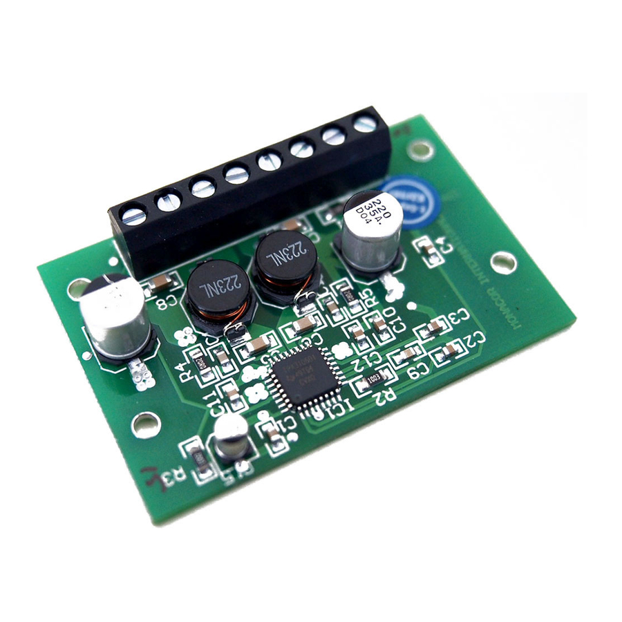
IPA-25D
Bestell-Nr. • Order No. 03.0790
ELECTRONICS FOR SPECIALISTS
ELECTRONICS FOR SPECIALISTS
Digital-Hi-Fi-Endstufenmodul
Diese Anleitung richtet sich an Anwender mit
Grundkenntnissen in der Elektronik. Bitte lesen Sie
die Anleitung vor dem Betrieb gründlich durch und
heben Sie sie für ein späteres Nachlesen auf.
1 Verwendungsmöglichkeiten
Das Modul IPA-25D eignet sich zum Aufbau von
Hi-Fi-Endverstärkern, Vollverstärkern mit Vorverstär-
kern und Aktiv-Lautsprecherboxen. Zum Aufbau
eines Stereoverstärkers sind zwei Module erforderlich.
Der IPA-25D ist ein Klasse-D-Verstärker, wodurch
ein hoher Wirkungsgrad (> 90 %) und geringe Ab-
messungen (kein Kühlkörper erforderlich) erreicht
werden. Der Lautsprecherausgang ist kurzschlussfest
und das IC gegen Überhitzung geschützt.
2 Wichtige Hinweise für den Gebrauch
Das Modul entspricht allen relevanten Richtlinien der
EU und trägt deshalb das
-Zeichen.
•
Das Modul i st nach der EMV-Richtlinie 2014 / 30/ EU
aufgebaut (EMV = Elektromagnetische Verträg-
lichkeit). Damit das Modul auch im Betrieb diese
Richtlinie erfüllt, muss es in ein abgeschirmtes Ge-
häuse eingesetzt und der Eingang über eine ab-
geschirmte Leitung angeschlossen werden. Wird
Digital Hi-Fi Power Amplifier Module
These instructions are intended for users with basic elec-
tronic knowledge. Please read the instructions carefully
prior to operation and keep them for later reference.
1 Applications
The module IPA-25D is designed to build Hi-Fi power
amplifiers, amplifiers with preamplifiers, and active
speaker systems. To build a stereo amplifier, two
modules are necessary.
The IPA-25D is a Class D amplifier; thus, it pro-
vides a high level of efficiency (> 90 %) and takes up
only little space (no heat sink required). The speaker
output is short-circuit proof and the IC is protected
against overheating.
2 Important Notes
The module corresponds to all relevant directives of
the EU and is therefore marked with
•
The module has been designed according to the
EMC directive 2014 / 30/ EU (EMC = electromag-
netic compatibility). To conform to this directive
while in operation, the module must be placed
into a shielded housing and the input must be con-
nected by means of a shielded cable. If the EMC
1
32
IC 1
C 14
L 2
L 1
STB COM IN
COM
LS-
LS+ VCC+ GND
1
Mute
Stand-by
IN
12 – 24 V
➀
ELECTRONICS FOR SPECIALISTS
die EMV-Richtlinie nicht eingehalten, erlischt die
Konformitätserklärung.
•
Wird das Modul zweckentfremdet, nicht richtig
angeschlossen oder nicht fachgerecht repariert,
kann keine Haftung für daraus resultierende Sach-
oder Personenschäden und keine Garantie für das
Modul übernommen werden.
Soll das Modul endgültig aus dem Betrieb
genommen werden, übergeben Sie es zur
umweltgerechten Entsorgung einem ört-
lichen Recyclingbetrieb.
3 Aufbau und Anschluss
Das Modul kann mithilfe von vier Abstandhaltern
durch die Bohrungen der Platine in ein Gehäuse ein-
gebaut werden. Beim Anschluss (siehe auch Abb. 1)
möglichst kurze Leitungen verwenden.
1 STB
Stummschalten und Stand-by-Betrieb
2 COM
Masse für die Stummschaltung
3 IN
Eingangssignal
4 COM
Masse für das Eingangssignal
5 LS−
Minuspol für den Lautsprecher
6 LS+
Pluspol für den Lautsprecher
7 VCC+
Betriebsspannung 12 – 24 V (⎓)
8 GND
Masse für die Betriebsspannung
directive is not complied with, the declaration of
conformity will no longer apply.
•
No guarantee claims for the module and no liability
for any resulting personal damage or material dam-
age will be accepted if the module is used for other
purposes than originally intended, if it is not correctly
connected or if it is not repaired in an expert way.
If the module is to be put out of operation
definitively, take it to a local recycling plant
for a disposal which is not harmful to the
environment.
3 Setup and Connection
To install the module into a housing, insert four
spacers through the drill holes of the PCB. For the
connections (also see fig. 1), use cables that are as
short as possible.
1 STB
Muting and standby operation
2 COM
Ground for muting
.
3 IN
Input signal
4 COM
Ground for the input signal
5 LS−
Negative pole for the speaker
6 LS+
Positive pole for the speaker
7 VCC+
Operating voltage 12 – 24 V (⎓)
8 GND
Ground for operating voltage
+12 V ... +24 V
Mute/Stand-by
Input
C 13
8
4 – 8 Ω
➁
MONACOR INTERNATIONAL GmbH & Co. KG • Zum Falsch 36 • 28307 Bremen • Germany
Copyright
by MONACOR INTERNATIONAL. All rights reserved.
©
ELECTRONICS FOR SPECIALISTS
7 VCC+
C15
R3
10µ
10k
1 STB
2 COM
32
31
30
C4
1µ
A VCC
FAULT
MUTE
3 IN
1
IN+
Input
4 COM
2
IN-
C2
R1
3
A GND
1µ
100k
4
A GND
5
GAIN0
6
GAIN1
7
MST/SLV
8
SYNC
R_OSC
VREG
VBYP
9
10
11
R2
C9
8 GND
100k
10n
ELECTRONICS FOR SPECIALISTS
ELECTRONICS
Wichtig! Keiner der beiden Lautsprecheranschlüsse
darf mit Masse verbunden werden (Brückenschal-
tung).
4 Technische Daten
Ausgangsleistung
Sinusleistung
bei Vcc = 24 V:. . . . . . 25 W
bei Vcc = 12 V:. . . . . . 15 W
Musikleistung
bei Vcc = 24 V:. . . . . . 45 W
bei Vcc = 12 V:. . . . . . 25 W
Klirrfaktor: . . . . . . . . . . . . < 0,2 % bei 1 W
Lastimpedanz: . . . . . . . . . 4 – 8 Ω
Frequenzbereich: . . . . . . . 10 – 20 000 Hz, −3 dB
Eingangsempfindlichkeit: . 140 mV
Eingangsimpedanz: . . . . . 12 kΩ
Störabstand: . . . . . . . . . . > 100 dB (A-bewertet)
Stromversorgung: . . . . . . 12 – 24 V (⎓), 2,5 A
Ruhestrom
Normalbetrieb: . . . . . . . 14 mA
Stand-by: . . . . . . . . . . . < 0,25 mA
Abmessungen: . . . . . . . . . 65 × 13 × 40 mm
Gewicht: . . . . . . . . . . . . . 25 g
Änderungen vorbehalten.
Important! Do not connect any of the two speaker
connections to ground (bridge circuit).
4 Specifications
Output power
RMS power
at Vcc = 24 V: . . . . . . 25 W
at Vcc = 12 V: . . . . . . 15 W
Music power
at Vcc = 24 V: . . . . . . 45 W
at Vcc = 12 V: . . . . . . 25 W
THD: . . . . . . . . . . . . . . . . < 0.2 % at 1 W
Load impedance: . . . . . . . 4 – 8 Ω
Frequency range: . . . . . . . 10 – 20 000 Hz, −3 dB
Input sensitivity: . . . . . . . 140 mV
Input impedance: . . . . . . . 12 kΩ
S / N ratio: . . . . . . . . . . . . > 100 dB (A-weighted)
Power supply: . . . . . . . . . 12 – 24 V (⎓), 2.5 A
Quiescent current
standard operation: . . . . 14 mA
standby operation: . . . . < 0.25 mA
Dimensions: . . . . . . . . . . . 65 × 13 × 40 mm
Weight: . . . . . . . . . . . . . . 25 g
Subject to technical modification.
C13
C1
C11
220µ
1µ
1µ
30 V
29
28
27
26
25
SD2
P VCC
P VCC
P VCC
P GND
24
P GND
23
BS P
22
OUT P
21
OUT P
IC1
TPA3106D1
20
OUT N
19
OUT N
18
BS N
17
P GND
A GND VCL AMP P VCC
P VCC
P GND
12
13
14
15
16
C14
C3
C10
C12
220µ
1µ
1µ
1µ
30 V
A-1548.99.02.02.2017
an 4 Ω
an 8 Ω
30 W
8 W
45 W
12 W
at 4 Ω
at 8 Ω
30 W
8 W
45 W
12 W
R4
20R
C16
1n
C5
µ22
LS+ 6
L2
22µ
C8
680n
Speaker
4 – 8 Ω
C7
L1
680n
22µ
LS- 5
C6
µ22
C17
1n
R5
20R
Werbung

Verwandte Anleitungen für Monacor IPA-25D


Inhaltszusammenfassung für Monacor IPA-25D
- Seite 1 P GND 12 – 24 V 220µ 8 GND 100k 1µ 1µ 1µ 30 V ➀ ➁ MONACOR INTERNATIONAL GmbH & Co. KG • Zum Falsch 36 • 28307 Bremen • Germany A-1548.99.02.02.2017 Copyright by MONACOR INTERNATIONAL. All rights reserved. ©...
- Seite 2 P GND 12 – 24 V 220µ 8 GND 100k 1µ 1µ 1µ 30 V ➀ ➁ MONACOR INTERNATIONAL GmbH & Co. KG • Zum Falsch 36 • 28307 Bremen • Germany A-1548.99.02.02.2017 Copyright by MONACOR INTERNATIONAL. All rights reserved. ©...