Toshiba MMU-AP0071MH Installations-Handbuch
Raumeinheit
Vorschau ausblenden
Andere Handbücher für MMU-AP0071MH:
- Betriebsanleitung (29 Seiten) ,
- Betriebsanleitung (230 Seiten)
Inhaltsverzeichnis
Werbung
Verfügbare Sprachen
Verfügbare Sprachen
Quicklinks
VOLUME-1
INSTALLATION MANUAL
MANUEL D’INSTALLATION
INSTALLATIONS-HANDBUCH
MANUALE DI INSTALLAZIONE
MANUAL DE INSTALACIÓN
AIR CONDITIONER
CLIMATISEUR
KLIMASYSTEM
CONDIZIONATORE D'ARIA
AIRE ACONDICIONADO
Indoor Unit
Strictly for commercial use only
Uniquement à usage commercial
Unité intérieure
Nur für den gewerblichen Bebrauch
Raumeinheit
Assolutamente solo per uso commerciale
Unità interna
Únicamente para uso comercial
Unidad interior
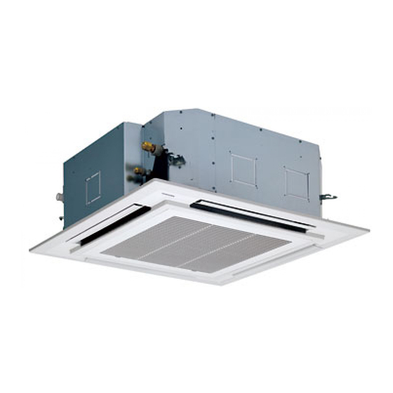
[4-way Air Discharge Cassette Type]
[Type cassette à 4 voies de soufflage]
[4-Wege-Kassetten-Modell]
[Tipo a cassetta per mandata d'aria a 4 vie]
[Modelo de cassette con descarga de aire de 4 vías]
MMU-AP0071MH
MMU-AP0091MH
MMU-AP0121MH
MMU-AP0151MH
MMU-AP0181MH
Downloaded from
www.Manualslib.com
manuals search engine
Werbung
Inhaltsverzeichnis
Fehlerbehebung

Verwandte Anleitungen für Toshiba MMU-AP0071MH


Inhaltszusammenfassung für Toshiba MMU-AP0071MH
- Seite 1 Unidad interior [4-way Air Discharge Cassette Type] [Type cassette à 4 voies de soufflage] [4-Wege-Kassetten-Modell] [Tipo a cassetta per mandata d'aria a 4 vie] [Modelo de cassette con descarga de aire de 4 vías] MMU-AP0071MH MMU-AP0091MH MMU-AP0121MH MMU-AP0151MH MMU-AP0181MH Downloaded from www.Manualslib.com...
- Seite 2 We would like to express our deepest thanks to your purchase this Air ADOPTION OF NEW REFRIGERANT Conditioner. This manual describes the details of installation method of the indoor This Air Conditioner adopts a new HFC refrigerant unit. (R410A) which does not destruct the ozone layer. Prior to installation, please read this manual thoroughly to understand the contents.
-
Seite 3: Inhaltsverzeichnis
VOLUME-1 CONTENTS Accessory parts and Parts to be procured locally ..1 ELECTRIC WORK ..........14 PRECAUTIONS FOR SAFETY ......2 APPLICABLE CONTROLS ....... 18 SELECTION OF INSTALLATION PLACE ... 3 TEST RUN ............21 INSTALLATION OF INDOOR UNIT ..... 5 TROUBLESHOOTING ........ -
Seite 4: Accessory Parts And Parts To Be Procured Locally
Accessory parts and Parts to be procured locally H Accessory parts Part name Q’ty Shape Usage Installation Manual This manual (Ensure handover to customer) Heat insulating pipe For heat insulation of the pipe connecting section Installation pattern —— For checking of ceiling opening and the main unit position For positioning of the ceiling position Installation gauge (To be used with the installation pattern) -
Seite 5: Precautions For Safety
PRECAUTIONS FOR SAFETY • Ensure that all Local, National and International regulations are satisfied. • Important safety information are describes in this installation manual. Please ensure this manual is read thoroughly and kept for future reference. • After the installation work, perform a trial operation to check for any problem. Follow the Owner’s Manual to explain how to use and maintain the unit to the customer. -
Seite 6: Selection Of Installation Place
PRECAUTIONS FOR SAFETY • Install the air conditioner securely in a location where the base can sustain the weight of the unit adequately. • Perform the specified installation work to guard against an earthquake. If the air conditioner is not installed appropriately, accidents may occur due to the unit falling. •... -
Seite 7: Installation Space
Installation space Ensure there is sufficient space to install the unit and to perform maintenance work as and when required. Keep 15mm or more for clearance between top plate of the indoor unit and the ceiling surface. Installation space 1000 or more 1000 or more Obstacle Ceiling height... -
Seite 8: In Case Of Wireless Type
SELECTION OF INSTALLATION PLACE In case of wireless type The wireless remote controller can be operated up to a maximum of 8 m from the infra-red receiver. Therefore ensure that the remote controller will be mounted and used within this stated parameter. •... - Seite 9 Dimensional view 595 to 660 Ceiling open dimension 1000 or more Check port 450) Check port 450) Check port 450) Obustacle Drain-up standing-up size Indoor unit 1000 or more Bottom face of ceiling Note) As ABS is used for the drain discharge port of the main unit, the vinyl chlor paste cannot be used.
- Seite 10 INSTALLATION OF INDOOR UNIT Ceiling opening and installation of hanging bolts • Evaluate and determine the piping and wiring requirements inside the ceiling prior to the hanging of the unit. • After installation place of the indoor unit has been determined, create opening in ceiling and install the hanging bolts.
- Seite 11 Installation of indoor unit Hanging bolt M10 flat washer (W3/8 or M10) (Accessory) • Attach the nut (M10 or W3/8: Procured locally) and washer (Ø34 mm) to the hanging bolt. (W3/8 or M10) M10 flat washer • Put washers at either side of the T-groove on the hanging bracket of (Accessory) the indoor unit in order to hang the unit.
-
Seite 12: Drain Piping Work
DRAIN PIPING WORK CAUTION Pipe material/Insulator and size The following materials for piping work and insulation • Install the drain piping so that the water are to be procured locally. drains effectively. Hard vinyl chloride pipe socket for VP25 • Apply heat insulation to prevent dew condensation from forming. - Seite 13 Connection of drain pipe Check the draining • Connect the hard socket (Procured locally) to the After completion of drain piping, hard socket side of the supplied flexible hose which Check water drains away and that no water leaks from has been installed.
- Seite 14 DRAIN PIPING WORK Thermal insulating process • After checking of the draining, using the supplied thermal insulation fit to the flexible hose leaving no clearance at the connecting port of the indoor unit. • Fit locally procured thermal insulation to the drain pipe leaving no clearance between the supplied insulation. Flexible hose Hose band CAUTION...
-
Seite 15: Refrigerant Piping
REFRIGERANT PIPING WARNING • If refrigerant gas leaks during the installation work, ventilate the room immediately. • If the leaked refrigerant comes in contact with fire, noxious gas may generate. • After the installation work, confirm that refrigerant does not leak. •... - Seite 16 REFRIGERANT PIPING • Projection margin in flaring : Airtight test/Air purge, etc. B (Unit : mm) For carrying out airtight test, air purge, gas leak check and addition of refrigerant refer to the Installation Manual supplied with the outdoor unit. Rigid (Clutch type) R410A tool used Conventional tool used...
-
Seite 17: Electric Work
ELECTRIC WORK WARNING 1. Using the specified wires, ensure the wires are connected and securely fixed so that no external force can transmit to the connecting part of the terminals. Poor connection may cause risk of fire, etc. 2. Ensure connection of earth wire. (Grounding work) Do not connect the earth wire to a gas pipe, mains water pipe, lightning rod, or the earth wire of a telephone. -
Seite 18: Power Supply Specifications
ELECTRIC WORK Power supply specifications Power supply wiring and communication wiring are to be procured locally. For the power supply specification, follow the table below. Ensure power supply is adequate. An insufficient power supply could result in unit failure. For specification of the power capacity of the outdoor unit and the power supply wires, refer to the Installation Manual supplied with the outdoor unit. -
Seite 19: Cable Connection
Cable connection REQUIREMENT • Be sure to locate the cable through the cable connection port of the indoor unit. • Ensure additional wire length of approximately 100 mm at the indoor unit electric parts box. This is to enable ease of any service work in the future. •... -
Seite 20: Address Setup
ELECTRIC WORK Remote controller wiring • Strip approximately 14 mm of insulation off of the connecting wires. • As the remote controller wire has no polarity, there is no problem if connections to indoor unit terminal blocks A and B are reversed. Wiring diagram Terminal block for remote controller Terminal block... -
Seite 21: Applicable Controls
APPLICABLE CONTROLS NOTIFICATION When using the equipment for the first time, the remote controller will not accept any commands for a short period of time. • Automatic address • While automatic addressing no operations can be performed on the remote control. •... -
Seite 22: In Case Of Installation To High Ceiling
APPLICABLE CONTROLS In case of installation to high ceiling When the unit is to be installed at a height that exceeds the standard value, adjustment to the air volume is necessary. • For the operation procedure, refer to the item “To incorporate a filter sold separately”. •... -
Seite 23: Group Control
Change of lighting time of filter sign Group control Depending on the conditions of the installation, the In a group control, a remote controller can control up time period of the filter clean sign can be changed. to a maximum of 8 units. Follow to the basic operation procedure •... -
Seite 24: Test Run
TEST RUN Before test operation WARNING • Before turning on the power supply, carry out the following To protect the compressor at procedures. startup. Ensure the power supply 1) Using 500V-megger, check there is 1MΩ or more between the is left on for 12 or more hours terminal block of the power supply and the earth. -
Seite 25: In Case Of Wireless Remote Controller
In case of wireless remote controller Procedure Description Remove a small screw which fixes the nameplate of the receiver unit. Remove the nameplate of the sensor section by inserting a minus screwdriver, etc into the notch at the bottom of the plate, and set the Dip switch to [TEST RUN ON]. Execute a test operation with button on the wireless remote controller. -
Seite 26: Troubleshooting
TROUBLESHOOTING Confirmation and check When a fault occurs in the air conditioner, the check CODE No. code and the indoor unit No. will appear on the display UNIT No. part of the remote controller. R.C. The check code will only be displayed while the unit is in operation. - Seite 27 Check method On the remote controller (Main remote controller, Central control remote controller) and the interface P.C. board of the outdoor unit, a check display LCD (Remote controller) or 7-segment display (on the outdoor interface P.C. board) operation is provided. Therefore the operation status can be known. Using this self-diagnosis function, a fault and the location of this fault within the air conditioning system can be located, as shown in the table below.
- Seite 28 TROUBLESHOOTING Check code Wireless remote controller Main Sensor block display Outdoor 7-segment display Check code name Judging device remote AI-NET central of receiving unit controller control display display Timer Ready Flash Auxiliary code Operation ¤ ¤ — — ALT Indoor TCJ sensor error Indoor ¤...
- Seite 29 Differs according to error contents of unit with occurrence of alarm Group control branching unit error TCC-LINK — — (L20 is displayed.) Duplicated central control addresses Terminology TCC-LINK : TOSHIBA Carriea Cominication Link. Downloaded from www.Manualslib.com manuals search engine...
- Seite 30 TROUBLESHOOTING New check code 1. Difference between the new check code and the current system The displaying method of the check code will change from this model onwards. Check code in current system New check code Used characters Hexadecimal notation, 2 digits Alphabet + Decimal notation, 2 digits Characteristics of code classification Few classification of communication/incorrect setup system...
-
Seite 31: Daily Maintenance
MAINTENANCE Prior to maintenance, ensure the power supply is turned off. CAUTION Do not handle the buttons with wet hands as this will cause the risk of electric shock. Daily maintenance Cleaning of air filter CODE No. is displayed on the remote controller, maintenance to the air filter is required. -
Seite 32: Pièces Accessoires Et Pièces Non Fournies
Pièces accessoires et pièces non fournies H Pièces accessoires Nom de la pièce Quantité Forme Emploi Manuel d’installation Ce manuel (N’oubliez pas de le remettre au client) Pour la gaine de calorifugeage des sections de raccordement des Gaine de calorifugeage tuyaux Gabarit d’installation ——... -
Seite 33: Mesures De Securite
MESURES DE SECURITE • Assurez-vous de respecter toutes les règles locales, nationales et internationales. • Ce manuel contient des informations essentielles pour la sécurité. Lisez attentivement ce manuel et rangez-le soigneusement pour pouvoir le consulter par la suite. • Après l’installation, faites un essai de fonctionnement pour vous assurer de l’absence de problèmes. Reportez-vous au Manuel du propriétaire pour expliquer au client comment utiliser l’unité... -
Seite 34: Selection Du Lieu D'installation
MESURES DE SECURITE • Installez solidement le climatiseur dans un endroit qui supporte son poids de manière adéquate. • Effectuez l’installation spécifiée pour protéger le climatiseur contre un tremblement de terre. Si le climatiseur n’est pas installé de manière appropriée, il peut tomber et provoquer des accidents. •... - Seite 35 Espace requis pour l’installation Vérifiez s’il y a assez de place pour installer l’unité et pour effectuer sont entretien en cas de besoin. Laissez au moins 15 mm entre le haut de l’unité intérieure et le plafond. Espace requis pour l’installation 1000 ou davantage 1000 ou davantage Obstacle...
-
Seite 36: Installation De L'unite Interieure
SELECTION DU LIEU D’INSTALLATION Sur les types sans-fil Vous pouvez utiliser la télécommande à 8 m maximum de distance du récepteur infrarouge. Vérifiez donc si la télécommande est montée et utilisée dans le respect de ces conditions. • Pour éviter les risques de dysfonctionnement, la télécommande ne doit être montée et utilisée à... - Seite 37 Vue de l’encombrement De 595 à 660 1000 ou davantage Dimension de l’ouverture du plafond Trappe d’inspection 450) Trappe d’inspection Trappe 450) d’inspection 450) Obstacle Dimension maxi de l’évacuation montante 1000 ou Unité intérieure davantage Bas du plafond REMARQUE) Comme l’orifice d’évacuation de l’unité principale est en ABS, vous ne pouvez pas utiliser de pâte de chlorure de vinyle.
- Seite 38 INSTALLATION DE L’UNITE INTERIEURE Ouverture du plafond et installation des boulons de suspension • Examinez et décidez des dimensions de la tuyauterie et du câblage nécessaires à l’intérieur du plafond avant de suspendre l’unité. • Après l’installation, placez l’unité intérieure à l’endroit prévu, pratiquez l’ouverture dans le plafond et installez les boulons de suspension.
- Seite 39 Installation de l’unité intérieure • Fixez l’écrou (M10 ou W3/8 : acheté sur place) et la rondelle jointe Rondelle plate Boulon de suspension M10 (accessoire) (Ø34 mm) au boulon de suspension. (W3/8 ou M10) • Posez des rondelles des deux côtés de la rainure du support de Ecrou suspension de l’unité...
-
Seite 40: Installation Des Tuyaux D'evacuation
INSTALLATION DES TUYAUX D’EVACUATION ATTENTION Tuyauterie/Isolant et dimension Les matériaux suivants servant aux travaux de • Montez le tuyau d’évacuation afin que l’eau plomberie et d’isolation doivent être achetés sur place. s’évacue correctement, • Posez de l’isolant thermique pour éviter la Manchon en chlorure de vinyle dur pour VP25 formation de condensats. - Seite 41 Raccordement du tuyau d’évacuation Vérification de l’évacuation • Raccordez le manchon dur (non fourni) sur le côté Au terme des travaux de plomberie. manchon dur du tuyau flexible fourni, déjà monté. Vérifiez si l’eau s’évacue correctement et s’il n’y a pas •...
- Seite 42 INSTALLATION DES TUYAUX D’EVACUATION Procédé de calorifugeage • Après avoir vérifié l’évacuation, posez de l’isolant thermique autour du tuyau flexible pour éliminer le jeu au niveau de l’orifice de raccordement sur l’unité intérieure. • Posez de l’isolant thermique acheté sur place autour du tuyau d’évacuation pour éliminer le jeu au niveau de l’isolant fourni.
-
Seite 43: Tuyaux De Réfrigérant
TUYAUX DE RÉFRIGÉRANT AVERTISSEMENT • Si le gaz réfrigérant fuit durant les travaux d’installation, aérez immédiatement la pièce. • Si le gaz réfrigérant qui a fui entre en contact avec le feu, un gaz nocif peut se dégager. • Après l’installation, vérifiez si le gaz réfrigérant ne fuit pas. •... - Seite 44 TUYAUX DE RÉFRIGÉRANT • Marge de projection de Test d’étanchéité/Purge d’air, etc. l’évasement : B (Unité : mm) Pour savoir comment effectuer le test d’étanchéité, la Rigide (de type à clabot) purge de l’air ou vérifier l’absence de fuites de gaz ou de réfrigérant, consultez le Manuel d’installation fourni avec l’unité...
-
Seite 45: Travaux D'électricité
TRAVAUX D’ÉLECTRICITÉ AVERTISSEMENT 1. Utilisez les conducteurs prescrits et vérifiez si les conducteurs sont solidement branchés de façon à ce qu’aucune force extérieure ne puisse se transmettre au raccordement des bornes. Les mauvais raccordements peuvent provoquer des incendies, etc. 2. Vérifiez le branchement du fil de terre. (Mise à la terre) Ne raccordez le fil de terre ni sur le tuyau de gaz, ni sur le tuyau de distribution d’eau, ni sur le paratonnerre, ni sur le fil de terre du téléphone. - Seite 46 TRAVAUX D’ÉLECTRICITÉ Caractéristiques de l’alimentation électrique Achetez sur place les fils électriques d’alimentation et les câbles de communication. Pour connaître les caractéristiques de l’alimentation électrique, consultez le tableau ci-dessous. Vérifiez si l’alimentation électrique est adéquate. Si l’alimentation électrique est insuffisante, l’unité risque de tomber en panne. Pour connaître la puissance de l’unité...
-
Seite 47: Raccordement Des Câbles
Raccordement des câbles CONDITIONS REQUISES • Assurez-vous de faire passer le câble à travers l’orifice de raccordement de l’unité intérieure. • Prévoyez une longueur de fil supplémentaire d’environ 100 mm au niveau du boîtier électrique de l’unité intérieure. Cela facilitera les par la suite les opérations d’entretien et de dépannage. •... - Seite 48 TRAVAUX D’ÉLECTRICITÉ Raccordement des télécommandes • Dénudez les fils de connexion sur environ 14 mm. • Le câble de la télécommande n’ayant pas de polarité, les connexions des bornes A et B de l’unité intérieure peuvent être inversées. Schéma de câblage Bornier de raccordement de la Bornier télécommande de l’unité...
-
Seite 49: Commandes Utilisables
COMMANDES UTILISABLES NOTIFICATION Lorsque vous utilisez l’appareil pour la première fois, la télécommande n’accepte les ordres qu’après un certain temps. • Adressage automatique • Pendant l’adressage automatique, la télécommande ne peut pas fonctionner. • L’adressage automatique dure au maximum 10 minutes (généralement 5 minutes). •... - Seite 50 COMMANDES UTILISABLES Pour le montage sur un haut plafond Si vous installez l’unité à une hauteur plus élevée que celle prévue, vous devez régler le débit d’air. • Pour connaître la procédure, consultez le paragraphe “Pour monter un filtre vendu séparément”. •...
-
Seite 51: Commande De Groupe
Modification du temps d’éclairage de la minuterie du filtre Vous pouvez modifier la durée de la minuterie de Paramètres Temps d’éclairage de nettoyage du filtre en fonction des conditions de de réglage la minuterie du filtre l’installation. Agissez conformément à la procédure de base 0000 Aucun →... -
Seite 52: Essai De Fonctionnement
ESSAI DE FONCTIONNEMENT Avant d’effectuer l’essai de fonctionnement AVERTISSEMENT • Avant de mettre le système sous tension, suivez la procédure ci-après. Pour protéger le compresseur 1) Avec un megohmmètre vérifiez s’il y a 1 MΩ ou davantage entre la au démarrage. N’oubliez pas borne de l’alimentation électrique et la terre. - Seite 53 Avec une télécommande sans-fil Procédure Description Enlevez toutes les petites vis de fixation de la plaque du constructeur du récepteur. Enlevez la plaque du constructeur du capteur en introduisant un petit tournevis dans l’encoche au bas de la plaque et placez l’interrupteur Dip sur [TEST RUN ON]. Exécutez un essai de fonctionnement à...
-
Seite 54: Dépannage
DÉPANNAGE Confirmation et vérification En cas de panne du climatiseur, le code de vérification CODE No. et le n° d’unité intérieure apparaissent sur l’afficheur de UNIT No. la télécommande. R.C. Le code de vérification ne s’affiche que pendant le fonctionnement de l’unité. Si l’affichage disparaît, faites fonctionner le climatiseur conformément au paragraphe suivant, Confirmation de Code de vérification... - Seite 55 Liste des codes de vérification La liste ci-dessous montre tous les codes de vérification. Trouvez sur la liste la vérification à effectuer sur la pièce à vérifier. • Dans le cas d’une vérification à partir de la télécommande intérieure : Consultez Affichage de la télécommande principale sur la liste.
- Seite 56 DÉPANNAGE Code de vérification Télécommande sans fil Afficheur du bloc capteur du Code auxiliaire Dispositif Afficheur de la Affichage de la récepteur Nom du code de vérification d’appréciation télécommande commande principale centrale AI NET Fonction Auxiliary code nement Minuterie Prête Clignote ¤...
- Seite 57 Alarme de groupe interface de commande appareils génériques Différent selon le contenu de la panne de l’unité en état d’alarme Panne branchement commande de groupe TCC-LINK — — (L20 s’affiche.) Adresses commande centrale doublées Terminologie TCC-LINK : TOSHIBA Carriea Cominication Link. Downloaded from www.Manualslib.com manuals search engine...
- Seite 58 DÉPANNAGE Nouveau code de vérification 1. Différence entre le nouveau code de vérification et le système courant La méthode d’affichage des codes de vérification change à partir de ce modèle. Code de vérification du système en cours Nouveau code de vérification Caractères utilisés Notation héxadécimale, 2 chiffres Alphabet + notation décimale, 2 chiffres...
-
Seite 59: Entretien Quotidien
ENTRETIEN Avant d’effectuer l’entretien, vérifiez si l’appareil est hors tension. ATTENTION Ne touchez pas les touches avec les mains humides pour ne pas vous électrocuter. Entretien quotidien Nettoyage du filtre à air CODE No. s’affiche sur la télécommande, procédez à l’entretien du filtre à... -
Seite 60: Zubehör Und Bauseits Bereitzustellende Teile
Zubehör und bauseits bereitzustellende Teile H Zubehör Teilebezeichnung Anzahl Form Anwendung Installations-Handbuch Dieses Handbuch (Für den Kunden) Wärmeisolierung Zur Isolierung der Rohrverbindungen Installationsvorlage — Zur Bestimmung der Deckenöffnung und der Position der Inneneinheit Zur Bestimmung der Deckenöffnung Installationslehre (gemeinsam mit der Installationsschablone) Montageschraube M5 ×... -
Seite 61: Sicherheitsvorkehrungen
SICHERHEITSVORKEHRUNGEN • Stellen Sie sicher, dass alle lokalen, nationalen und internationalen Vorschriften eingehalten werden. • Dieses Installationshandbuch enthält wichtige Sicherheitshinweise. Lesen Sie das Handbuch sorgfältig und verwahren Sie es für später. • Führen Sie nach der Installation einen Testlauf durch, um das System auf Fehler zu prüfen. Erklären Sie dem Kunden anhand der Betriebsanleitung, wie das Gerät bedient und gewartet wird. -
Seite 62: Auswahl Des Aufstellungsortes
SICHERHEITSVORKEHRUNGEN • Falls Sie in einem erdbebengefährdeten Gebiet leben, achten Sie bei der Installation auf eine entsprechende Auslegung der Befestigung. Ist das Klimagerät nicht richtig montiert, kann es herunter stürzen und so Verletzungen verursachen. • Ist während der Installation Kühlmittel ausgetreten, lüften Sie den Raum umgehend. Kommen Kühlmitteldämpfe in Kontakt mit Feuer, können sich gesundheitsschädliche Gase bilden. -
Seite 63: Liste Der Möglichen Raumhöhen
Platzbedarf Vergewissern Sie sich, dass der Platz für die Installation und der späteren Wartung des Geräts ausreicht. Sorgen Sie dafür, dass zwischen dem Deckel des Raumgeräts und der Decke mindesten 15 mm Platz sind. Platzbedarf 1000 oder größer 1000 oder größer Hindernis Deckenhöhe Modell MMU-... -
Seite 64: Für Drahtlose Fernbedienungen
AUSWAHL DES AUFSTELLUNGSORTES Für drahtlose Fernbedienungen Die Reichweite der Infrarotfernbedienung zum Empfänger beträgt maximal 8 m. Stellen Sie daher sicher, dass die Fernbedienung innerhalb dieses Abstands befestigt und benutzt wird. • Um eine sichere Funktion der Fernbedienung zu gewährleisten, darf Sie nicht im Bereich einer Leuchtstofflampe oder in direktem Sonnenlicht installiert werden. -
Seite 65: Maßzeichnungen
Maßzeichnungen 1000 oder größer Deckenöffnung 595 bis 660 mm Wartungsöffnung 450) Hindernis Höhe der Ablaufleitung 1000 Raumeinheit oder größer Unterseite der Decke HINWEIS) Wenn ABS als Ablaufrohr für das Hauptgerät verwendet wird, darf kein PVC-Kleber verwendet werden Verwenden sie den Platz für Installation beiliegenden flexiblen Schlauch (Schellenbefestigung) und Wartung... -
Seite 66: Deckenöffnung Und Montage Der Aufhängebolzen
INSTALLATION DER RAUMEINHEIT Deckenöffnung und Montage der Aufhängebolzen • Legen Sie die Führung der Rohrleitungen und Kabel innerhalb der Zwischendecke fest, bevor Sie das Gerät installieren. • Nachdem Sie den Platz für das Gerät festgelegt haben, erstellen Sie die Deckenöffnung und installieren Sie die Abhängebolzen. -
Seite 67: Xinstallation Der Fernbedienung (Getrennt Erhältlich)X
Installation der Raumeinheit Aufhängebolzen Unterlegscheibe, (W3/8 oder M10) flach M10 • Montieren Sie Muttern (W3/8 oder M10: Bauseits beizustellen) und (Zubehör) Unterlegscheiben (Ø34 mm) an den Abhängebolzen. Mutter (W3/8 oder M10) • Befestigen Sie Unterlegscheiben oberhalb und unterhalb der T-Nut der Unterlegscheibe, Abhängung der Inneneinheit und hängen Sie sie auf. -
Seite 68: Installation Des Kondenswasser-Ablaufs
INSTALLATION DES KONDENSWASSER-ABLAUFS VORSICHT Rohrmaterial/Isolation und Abmessung Die folgenden Materialien für die Verrohrung und die • Installieren Sie die Kondensatleitung so, dass Isolation müssen bauseits beigestellt werden. das Wasser problemlos abfließen kann. PVC-Rohranschluss VP25 • Isolieren Sie die Leitung, damit sich kein Kondenswasser bilden kann. -
Seite 69: Anschluss Des Ablaufschlauchs
Anschluss des Ablaufschlauchs Ablauf überprüfen • Verbinden Sie die PVC-Anschluss (bauseits Nach Montage der Kondensatleitung bereitgestellt) mit der PVC-Seite des installierten Prüfen Sie, ob das Wasser abläuft und an den Ablaufschlauchs. Verbindungsstellen nicht austritt. Prüfen Sie die • Schließen Sie danach die Ablaufrohre (bauseits Kondensatpumpe auf ungewöhnliche Geräusche. -
Seite 70: Wärmeisolierung
INSTALLATION DES KONDENSWASSER-ABLAUFS Wärmeisolierung • Nachdem Sie den Kondensatablauf überprüft haben, isolieren Sie den Schlauch und den Anschluss an der Inneneinheit mit dem mitgelieferten Isoliermaterial. • Isolieren Sie die Kondensatleitung mit bauseits beigestelltem Isoliermaterial, ohne dass Zwischenräume zwischen den Isolierungen entstehen. VORSICHT Flexibler Schlauch:... -
Seite 71: Kühlmittelleitungen
KÜHLMITTELLEITUNGEN WARNUNG • Belüften Sie den Raum sofort, wenn während der Installationsarbeiten Kältemittel austreten sollte. • Kommen Kältemitteldämpfe in Kontakt mit Feuer, können sich gesundheitsschädliche Gase bilden. • Vergewissern Sie sich daher nach der Installation noch einmal, dass kein Kältemittel austreten kann. •... - Seite 72 KÜHLMITTELLEITUNGEN • Bördelhöhe: B (Einheit: mm) Dichtetest/Entlüftung usw. Details zum Dichtigkeitstest, zur Entlüftung, zur Überprüfung auf Gaslecks und zum Auffüllen von Starr (Kupplung) Kältemittel finden Sie im Installationshandbuch der Außeneinheit. Spezielles R410A Herkömmliches Außendurchmesser Werkzeug Werkzeug des Kupferrohrs Öffnen Sie das Ventil der Außeneinheit R410A R410A ganz...
-
Seite 73: Elektroarbeiten
ELEKTROARBEITEN WARNUNG 1. Verwenden Sie nur spezifizierte Kabel und schließen Sie sie sicher an die Kontakte an. Achten Sie auf eine Zugentlastung, damit die Kontakte nicht belastet werden. Durch schlechte Anschlüsse kann es zu einem Brand kommen. 2. Stellen Sie sicher, dass die Masseleitung angeschlossen ist. (Erdung) Schließen Sie die Masseleitung nicht an Gas- oder Wasserrohre beziehungsweise Blitzableiter oder die Erdung der Telefonleitung an. -
Seite 74: Spezifikation Der Stromversorgung
ELEKTROARBEITEN Spezifikation der Stromversorgung Die Kabel der Stromversorgung und die Kommunikationskabel müssen bauseits beigestellt werden. Die Spezifikation der Stromversorgung finden Sie in der nachfolgenden Tabelle. Stellen Sie sicher, dass die Stromversorgung den Anforderungen entspricht. Durch eine falsche Versorgung kann es zu Schäden am Gerät kommen. Details zur Stromaufnahme und zu den Versorgungskabeln der Außeneinheit finden Sie im Installationshandbuch der Außeneinheit. -
Seite 75: Kabelanschlüsse
Kabelanschlüsse VORAUSSETZUNGEN • Führen Sie die Kabel durch die Kabeldurchführung der Raumeinheit. • Das Kabel muss am Schaltkasten der Inneneinheit eine Überlänge von etwa 100 mm haben. So werden spätere Wartungsarbeiten erleichtert. • Die Fernbedienung wird mit Niederspannung betrieben. • Entfernen Sie den Deckel des Schalkastens, indem sie die 3 Schrauben lösen und gegen die Haken drücken. (Der Deckel bleibt im Scharnier hängen.) •... - Seite 76 ELEKTROARBEITEN Verkabelung der Fernbedienung • Isolieren Sie die Verbindungskabel etwa 14 mm ab. • Da die Fernbedienungskabel keine Polarität haben, spielt es keine Rolle, wenn die Anschlussklemmen A und B vertauscht werden. Schaltplan Klemmenleiste für das Klemmenleiste Fernbedienungskabel der Inneneinheit Fernbedienung Kabel der Fernbedienung (bauseits beigestellt) Verbindungskabel zwischen Raum- und Außeneinheit...
-
Seite 77: Steuerungsmöglichkeiten
STEUERUNGSMÖGLICHKEITEN HINWEISE Wird das Gerät das erste Mal verwendet, reagiert die Fernbedienung für einige Zeit nicht auf das Drücken der Tasten. • Automatische Adressierung • Während die automatische Adressierung durchgeführt wird, kann die Fernbedienung nicht benutzt werden. • Die automatische Adressierung dauert maximal 10 Minuten (im Allgemeinen 5 Minuten). •... -
Seite 78: Installation Bei Großer Deckenhöhe
STEUERUNGSMÖGLICHKEITEN Installation bei großer Deckenhöhe Wenn die Einbauhöhe die Standardwerte überschreitet muss das Luftvolumen entsprechend eingestellt werden. • Die Vorgehensweise finden Sie um Absatz “Betrieb mit Zusatzfilter” in diesem Handbuch. • Wählen Sie die “Vorgabedaten” für Punkt aus der “Liste der möglichen Raumhöhen”. Bei fernbedienungsloser Steuerung (Gruppensteuerung) Soll das Gerät für hohe Einbauhöhen eingerichtet werden, wird die Stellung einer Brücke auf der Leiterplatte der Inneneinheit geändert. -
Seite 79: Änderung Der Zeitvorgabe Für Die Filterwarnleuchte
Änderung der Zeitvorgabe für die Filterwarnleuchte Die Zeitvorgabe für die Filterwarnleuchte kann den Einstelldaten Zeitvorgabe jeweiligen Installationsbedingungen angepasst werden. Folgen Sie den Vorgehensweisen 0000 Ohne → → → → → 0001 150H • Für den Code in Vorgehensweise geben Sie [01] ein. -
Seite 80: Vorbereitung
TESTLAUF Vorbereitung WARNUNG • Prüfen Sie folgende Punkte, ehe Sie die Stromversorgung einschalten: Zum Schutz des Verdichters 1) Prüfen Sie mit einem 500V Multimeter, ob zwischen den beim Start schalten Sie die Anschlüssen 1 bis 3 und Masse 1 MΩ oder mehr gemessen Stromversorgung mindestens 12 werden. -
Seite 81: Infrarot-Fernbedienung
Infrarot-Fernbedienung Vorgehensweise Beschreibung Entfernen Sie alle Schrauben des Typenschilds des Signalempfängers. Entfernen Sie das Typenschild des Sensors, indem Sie einen kleinen Schraubenzieher in die Nut unten auf der Platte drücken. Stellen Sie den DIP-Schalter auf [TEST RUN ON] ein. Führen Sie mit Hilfe der Taste auf der Infrarot-Fernbedienung einen Testlauf durch. -
Seite 82: Bestätigung Und Prüfung
FEHLERSUCHE Bestätigung und Prüfung CODE No. Tritt ein Fehler auf, erscheint in der Anzeige der Fernbedienung eine entsprechende Kennziffer und die UNIT No. Nummer der betroffenen Inneneinheit. R.C. Die Kennziffer wird nur angezeigt, wenn das Gerät arbeitet. Erlischt die Anzeige, gehen Sie wie in dem Absatz “Aufruf des Fehlerspeichers”... -
Seite 83: Liste Der Fehlercodes
Liste der Fehlercodes In der folgenden Liste finden Sie alle Fehlercodes. Finden Sie anhand der Liste den jeweiligen Prüfinhalt für die einzelnen Teile. • Fehleranzeige auf der Fernbedienung der Inneneinheit: Siehe “Anzeige Hauptfernbedienung” in der Liste. • Fehler an der Außeneinheit: Siehe “7-Segment-Anzeige, Außeneinheit” in der Liste. •... - Seite 84 FEHLERSUCHE Prüfcode Infrarot-Fernbedienung Sensorblockanzeige an Anzeigendes 7-Segmentanzeige, Außeneinheit Fehlercode-Bezeichnung Hauptfernbedienungs- AI-NET- Empfänger Gerät Anzeige Fernbedienungsanzeige Hilfscode Funktion Bereit Blinken ¤ ¤ — — Raumgerät TCJ-Sensorfehler Raumgerät ¤ ¤ — — Raumgerät TC2-Sensorfehler Raumgerät ¤ ¤ — — Raumgerät TC1-Sensorfehler Raumgerät ¡...
-
Seite 85: Fehler Durch Zentrale Überwachung Tcc-Link Erkannt
Allgemeiner Batch-Alarm durch Allgemeine Geräte — — — — Überwachungsschnittstelle Unterscheidet sich, abhängig vom Fehlerinhalt der fehlerhaften Einheit Gruppen-Überwachungsfehler TCC-LINK (L20 wird angezeigt.) — — Doppelte Adressierung Zentralsteuerung Terminologie TCC-LINK : TOSHIBA Carrier Communication Link. Downloaded from www.Manualslib.com manuals search engine... -
Seite 86: Neuer Prüfcode
FEHLERSUCHE Neuer Prüfcode 1. Unterschied zwischen dem neuen Prüfcode und dem bisherigen System Die Anzeige des Prüfcodes ändert sich mit diesem Modell und für zukünftige Modelle. Prüfcode bei bisherigen Systemen Neuer Prüfcode Verwendete Zeichen Hexadezimal, 2 Zeichen Alphanumerisch, 2 Zeichen Charakteristik der Geringe Klassifizierungen bei Kommunikation/ Zahlreiche Klassifizierungen bei Kommunikation/falscher... -
Seite 87: Wartung
WARTUNG Vergewissern Sie sich vor Wartungsarbeiten, dass die Stromversorgung abgeschaltet ist. VORSICHT Berühren Sie die Schalter nicht mit nassen Händen, da dies zu einem Stromschlag führen kann. Tägliche Wartung: Reinigen des Luftfilters CODE No. Wird auf der Fernbedienung angezeigt, muss der Luftfilter gereinigt werden. -
Seite 88: Accessori E Parti Da Acquistare Sul Posto
Accessori e parti da acquistare sul posto H Accessori Nome delle parti Q.tà Forma Utilizzo Manuale di installazione Questo manuale (Non mancare di consegnarlo ai clienti.) Tubo per isolamento da Per isolamento per riscaldamento della sezione di connessione dei tubi riscaldamento Sagoma per l’installazione ——... -
Seite 89: Precauzioni Per La Sicurezza
PRECAUZIONI PER LA SICUREZZA • Accertarsi che siano rispettate tutte le disposizioni vigenti a livello locale, nazionale e internazionale. • Questo manuale d’installazione contiene informazioni importanti ai fini della sicurezza. Assicurarsi che questo manuale venga letto attentamente e conservato per essere consultato in futuro. •... -
Seite 90: Scelta Del Posto D'installazione
PRECAUZIONI PER LA SICUREZZA • Installare il condizionatore d’aria saldamente in un posto in cui la base possa sostenerne adeguatamente il peso. • Eseguire il lavoro d’installazione specificato osservando le misure antisismiche. Se il condizionatore non è installato correttamente, l’apparecchio potrebbe cadere ed essere causa d’infortuni. •... - Seite 91 Spazio per l’installazione Assicurarsi che ci sia lo spazio necessario all’installazione dell’unità per eseguire gli interventi di assistenza tecnica come e quando necessari. Lasciare almeno 15 mm di spazio tra la piastra superiore dell'unità interna e la superficie del soffitto. Spazio per l’installazione 1000 o più...
-
Seite 92: Installazione Dell'unità Interna
SCELTA DEL POSTO D’INSTALLAZIONE Nel caso del tipo via radio Il telecomando via radio può essere usato in un raggio massimo di 8 m dal ricevitore d’infrarossi. Bisogna pertanto che il telecomando sia montato e usato rispettando questo parametro. • Per evitare problemi di funzionamento, non montare né... - Seite 93 Vista con dimensioni Grandezza apertura a soffitto, da 595 a 660 1000 o più Porta di controllo 450) Ostacolo Formato supporto con scarico in su Unità interna 1000 o più Facciata inferiore del soffitto NOTA) Siccome ABS è usato per la presa di mandata dello scarico dell’unità...
- Seite 94 INSTALLAZIONE DELL’UNITÀ INTERNA Apertura a soffitto e installazione dei bulloni di sospensione • Prima di appendere l’unità, valutare e determinare le necessità per tubazioni e collegamenti elettrici all’interno del soffitto. • Dopo aver stabilito la posizione d’installazione dell’unità interna, creare l’apertura nel soffitto e installare i bulloni di sospensione.
- Seite 95 Installazione dell'unità interna Bullone di Rondella • Attaccare il dado (M10 o W3/8: Da acquistare sul posto) e la rondella sospensione piatta M10 (W3/8 o M10) (Ø34 mm) al bullone di sospensione. (Accessorio) • Mettere le rondelle ai due lati della scanalatura a T sulla staffa di Dado sospensione dell’unità...
-
Seite 96: Lavoro Per Tubazione Di Scarico
LAVORO PER TUBAZIONE DI SCARICO AVVERTENZA Materiale per tubazioni/Isolamento e formato È necessario acquistare sul posto i seguenti materiali per • Installare il tubo dello scarico in modo che isolamento termico e posa in opera delle tubature. l’acqua sia scaricata senza problemi. •... - Seite 97 Connessione del tubo di scarico Controllare lo scarico • Collegare la presa rigida (da acquistare sul posto) Dopo aver completato il tubo di scarico, alla presa rigida del tubo flessibile, in dotazione, già Controllare che che l’acqua di scarico scorra e non ci installato.
- Seite 98 LAVORO PER TUBAZIONE DI SCARICO Procedura per isolamento termico • Dopo aver controllato lo scarico, utilizzando l’isolante termico, fornito in dotazione, avvolgere tutto il tubo flessibile senza lasciare spazi vuoti, partendo dall’attacco di connessione dell’unità interna. • Isolare termicamente il tubo di scarico usando l’isolante termico che deve essere acquistato sul posto e non lasciare spazi non isolati.
-
Seite 99: Tubazioni Del Refrigerante
TUBAZIONI DEL REFRIGERANTE TTENZIONE • In caso di perdite di gas refrigerante durante l’installazione, subito arieggiare il locale. • Il contatto fra il gas refrigerante, in caso di perdite, e il fuoco può produrre gas tossici. • Completato il lavoro d’installazione, accertarsi che non ci siano perdite di gas refrigerante. •... - Seite 100 TUBAZIONI DEL REFRIGERANTE • Margine di protezione in Prove di tenuta d’aria/Sfiato aria, ecc. svasatura: B (Unità mm] Rigido (Tipo a innesto) Per le prove di tenuta d’aria, spurgo dell’aria, perdita di gas, controlare e aggiungere refrigerante facendo riferimento al manuale d’installazione fornito insieme all’unità...
-
Seite 101: Collegamenti Elettrici
COLLEGAMENTI ELETTRICI TTENZIONE 1. Usando cavi da specifiche, fare i collegamenti e fissare i cavi in modo che pur sollecitate da forze esterne le parti di connessione dei terminali non siano danneggiate. Collegamenti incompleti possono causare incendi, ecc. 2. Non mancare di collegare il filo di messa a terra elettrica. (Collegamento elettrico di messa a terra) Non collegare il filo di messa terra a un tubo del gas o dell’acqua, al conduttore di un parafulmini o al filo di messa a terra dell’impianto telefonico. - Seite 102 COLLEGAMENTI ELETTRICI Dati tecnici per alimentazione elettrica I fili per i collegamenti d’alimentazione elettrica e per la trasmissione dei segnali di comunicazione devono essere acquistati sul posto. Per i dati tecnici per i collegamenti d’alimentazione elettrica, vedere la tabella riportata qui sotto. Controllare che la potenza d’alimentazione elettrica sia adeguata.
-
Seite 103: Collegamento Dei Cavi
Collegamento dei cavi REQUISITI • Il cavo deve passare attraverso la porta per collegamento cavi d’unità interna. • Assicurare una lunghezza di filo addizionale di circa 100 mm alla cassetta dei componenti elettrici dell’unità interna. Questo al fine di facilitare futuri interventi di assistenza tecnica. •... - Seite 104 COLLEGAMENTI ELETTRICI Posa in opera dei cavi per il telecomando • Spelare di circa 14 mm l’isolante dei fili di collegamento elettrico. • Siccome il filo del telecomando non è polarizzato, non ci sono rischi di guasti per inversione nelle connessioni alle morsettiere A e B dell’unità...
-
Seite 105: Comandi Applicabili
COMANDI APPLICABILI AVVISO Quando si utilizza l’apparecchio per la prima volta, per un breve periodo di tempo il telecomando non accetta comandi. • Indirizzamento automatico • Mentre è in corso l’indirizzamento automatico, non è possibile eseguire nessuna operazione sul telecomando. •... -
Seite 106: In Caso D'installazione A Soffitto Alto
COMANDI APPLICABILI In caso d’installazione a soffitto alto Quando l’unità deve essere installata ad un’altezza superiore al valore standard, bisogna regolare la portata dell’aria. • Per la procedura di funzionamento, fare riferimento al capitolo “Per inserire un filtro, da acquistare a parte”. •... - Seite 107 Modifica del tempo di accensione del simbolo del filtro A seconda delle condizioni di installazione, è possibile modificare il tempo di accensione del richiamo a pulire Dati da Tempo di accensione il filtro. impostare del simbolo del filtro Eseguire la procedura operativa di base 0000 None →...
-
Seite 108: Funzionamento Di Prova
FUNZIONAMENTO DI PROVA Prima del funzionamento di prova TTENZIONE • Prima di accendere l’alimentazione elettrica, eseguire la procedura Per proteggere il compressore seguente. all’avviamento. Assicurarsi che l’interruttore d’alimentazione resti 1) Usando un megger da 500 V, controllare che ci sia 1 MΩ o più acceso per 12 o più... - Seite 109 In caso di telecomando via radio Procedura Descrizione Rimuovere la piccola vite che fissa la targhetta dell’unità ricevente. Rimuovere la targhetta della sezione del sensore inserendo un cacciavite a testa piatta, ecc. nell’intaglio in fondo alla piastra e impostare il microinterruttore su [TEST RUN ON]. Eseguire un funzionamento di prova tramite il tasto del telecomando via radio.
-
Seite 110: Risoluzione Dei Problemi
RISOLUZIONE DEI PROBLEMI Conferma e controllo CODE No. In caso di problema di funzionamento del condizionatore d’aria, sul display del telecomando UNIT No. appaiono il codice di controllo e il No. d’unità interna. R.C. Il codice di controllo viene visualizzato solo durante il funzionamento dell’unità. - Seite 111 Lista dei codici di controllo La tabella seguente presenta i singoli codici di controllo. Individuare i contenuti dei controlli dalla lista in funzione della parte da controllare. • In caso di guasto dal telecomando di unità interna: Vedere la voce dell’elenco “Display del telecomando principale”. •...
- Seite 112 RISOLUZIONE DEI PROBLEMI Codice di controllo Telecomando via radio Display di Display del blocco sensore Dispositivo di Nome del codice di controllo Display del Display a 7 segmenti d’unità esterna comando di unità ricevente valutazione telecomando centralizzato principale Codice ausiliare AI-NET Funzionamento Timer Pronto Lampeggiante...
- Seite 113 Diverso in funzione di contenuti di errore di unità con evento di allarme Errore unità raggruppante controllo di gruppo TCC-LINK (L20 è visualizzato..) — — Indirizzi di controllo centralizzati ripetuti Terminologia TCC-LINK : TOSHIBA Carriea Cominication Link. Downloaded from www.Manualslib.com manuals search engine...
- Seite 114 RISOLUZIONE DEI PROBLEMI Nuovo codice di controllo 1. Differenza tra codice di controllo nuovo e sistema corrente Da questo modello in avanti il metodo di visualizzazione del codice di controllo cambia. Codici di controllo in sistema corrente Nuovo codice di controllo Caratteri usati Nota esadecimale, 2 cifre Alfabeto + Nota decimale, 2 cifre...
-
Seite 115: Manutenzione
MANUTENZIONE Prima di un intervento di manutenzione, accertarsi che l’unità sia spenta. AVVERTENZA Non toccare nessun interruttore con le mani bagnate, per evitare rischio di scossa elettrica. Manutenzione giornaliera Pulizia del filtro dell'aria CODE No. Se sul telecomando viene visualizzata l'indicazione è... -
Seite 116: Componentes Accesorios Y Componentes De Suministro Local
Componentes accesorios y componentes de suministro local H Componentes accesorios Nombre del componente Cantidad Forma Utilización Manual de instalación Este manual (Recuerde entregar al cliente) Para el aislamiento térmico de la sección de conexión de Tubo de aislamiento térmico tubos Patrón de instalación —... -
Seite 117: Precauciones Para Su Seguridad
PRECAUCIONES PARA SU SEGURIDAD • Asegúrese de que se cumplan todas las leyes locales, nacionales e internacionales. • En el presente manual se incluye información importante sobre la seguridad. Léalo con suma atención y guárdelo para referencia futura. • Una vez finalizada la instalación, efectúe una prueba de funcionamiento para comprobar si existe algún problema. Con ayuda del Manual del propietario, explique al cliente cómo debe utilizar y realizar el mantenimiento de la unidad. -
Seite 118: Selección Del Lugar De Instalación
PRECAUCIONES PARA SU SEGURIDAD • Instale el aparato de aire acondicionado de manera segura, en una ubicación en la que la base pueda aguantar perfectamente el peso de la unidad. • Realice las tareas de instalación específicas para proteger el aparato ante terremotos. Si el aparato de aire acondicionado no se instala correctamente, podrían producirse accidentes al caer la unidad. -
Seite 119: Espacio De Instalación
Espacio de instalación Observe que haya suficiente espacio para instalar la unidad y para realizar los trabajos de mantenimiento siempre que sean necesarios. Deje 15 mm o más de espacio entre la parte superior de la unidad interior y la superficie del techo. Espacio de instalación 1000 o más 1000 o más... -
Seite 120: Instalación De La Unidad Interior
SELECCIÓN DEL LUGAR DE INSTALACIÓN En el caso de mando a inalámbrico Se puede operar el control remoto inalámbrico hasta un máximo de 8 m de distancia del receptor infrarrojo. Verifique, por ello, que se instale y utilice el control remoto dentro de este parámetro. - Seite 121 Vista con dimensiones Dimensiones de la abertura de techo: 1000 o más entre 595 y 660 Orificio de inspección 450) Obstáculo Elevación total del drenaje ascendente Unidad interior 1000 o más Parte inferior del techo Nota) Dado que el ABS se utiliza en el puerto de descarga de drenaje de la unidad principal, no se puede utilizar pasta de cloruro vinílico.
- Seite 122 INSTALACIÓN DE LA UNIDAD INTERIOR Abertura del techo e instalación de los pernos de suspensión • Evalúe y determine los requisitos de la tubería y del cableado del techo, antes de colgar la unidad. • Después de haber decidido el sitio de instalación de la unidad interior, cree una abertura en el techo y coloque los pernos de suspensión.
- Seite 123 Instalación de la unidad interior • Coloque la tuerca (M10 o W3/8: De obtención local) y arandela Arandela plana M10 Perno de suspensión (Ø34 mm) al perno de suspensión. (accesorio) (W3/8 o M10) • Coloque arandelas de cada lado de la ranura en T de la ménsula Tuerca colgante de la unidad interior, para colgar la unidad.
-
Seite 124: Canalización De Drenaje
CANALIZACIÓN DE DRENAJE PRECAUCIÓN Material del tubo / Aislante y tamaño Los siguientes materiales para la canalización y • Instale la tubería de desagüe de modo que el aislación deberán adquirirse localmente. agua drene correctamente. • Aplique aislación térmica para evitar que se Manguito del tubo rígido de cloruro vinílico para VP25 forme condensación de vapor. - Seite 125 Conexión del tubo de drenaje Compruebe el drenaje • Conecte el manguito rígido (de suministro local) al Una vez realizada la tubería de desagüe. lado del manguito rígido de la manguera flexible Verifique que el agua salga y que no haya ninguna fuga (que ya ha sido instalada) incluida con el producto.
- Seite 126 CANALIZACIÓN DE DRENAJE Proceso de aislamiento térmico • Después de verificar el desagüe, acople la aislación térmica incluida a la manguera flexible, sin dejar espacio en el orificio de conexión de la unidad interior. • Ajuste la aislación térmica de adquisición local al tubo de desagüe, sin dejar separación entre la aislación provista. PRECAUCIÓN Manguera Abrazadera de...
-
Seite 127: Tubería De Regrigerante
TUBERÍA DE REGRIGERANTE ADVERTENCIA • Si hay un escape de gas refrigerante durante la instalación, ventile la habitación de inmediato. • Si el refrigerante del escape entra en contacto con fuego, podría generarse un gas nocivo. • Una vez finalizadas las tareas de instalación, asegúrese de que no hay escapes de refrigerante. •... - Seite 128 TUBERÍA DE REGRIGERANTE • Margen de proyección en el Prueba de hermetizado, purga de aire, etc. abocinado: B (unidad: mm) Para realizar pruebas de estanqueidad, purgar aire, comprobar si hay escapes de gas, y añadir Rígido (tipo embrague) refrigerante, consulte el Manual de instalación de la unidad exterior.
-
Seite 129: Instalación Eléctrica
INSTALACIÓN ELÉCTRICA ADVERTENCIA 1. Utilizando los cables especificados, asegúrese de conectar los cables y de unirlos bien, de manera que la fuerza externa no se transmita a la parte de conexión de los terminales. Una conexión deficiente puede crear riesgo de incendio, etc. 2. - Seite 130 INSTALACIÓN ELÉCTRICA Especificaciones de la alimentación eléctrica Debe adquirir localmente el cableado para la fuente de alimentación y para comunicaciones. Para conocer las especificaciones de la fuente de alimentación, consulte la tabla siguiente. Verifique que la alimentación eléctrica sea correcta. Si es insuficiente, puede provocar la falla de la unidad.
-
Seite 131: Conexión De Los Cables
Conexión de los cables REQUISITOS • Asegúrese de ubicar el cable por el orificio de conexión del cableado de la unidad interior. • Garantice una longitud de cable extra de unos 100 mm en la caja de componentes eléctricos de la unidad interior. - Seite 132 INSTALACIÓN ELÉCTRICA Cableado del mando a distancia • Quite aproximadamente 14 mm de la aislación de los cables de conexión. • Dado que el cable del mando a distancia no tiene polaridad, no pasa nada si se invierten las conexiones con los bloques de terminales A y B de la unidad interior.
-
Seite 133: Controles Aplicables
CONTROLES APLICABLES NOTIFICACIÓN Si utiliza el equipo por primera vez, el control remoto no acepta ningún comando por un breve lapso. • Identificación automática • Mientras se realiza la identificación automática, no se puede realizar ninguna operación desde el control remoto. •... - Seite 134 CONTROLES APLICABLES En el caso de instalar en un techo alto Cuando la altura del techo en el que se quiere instalar la unidad sea superior al valor estándar, debe ajustarse el volumen de aire. • Consulte el apartado “Para incorporar un filtro vendido por separado” para más información acerca del procedimiento de configuración.
- Seite 135 Cambiar momento de encendido de la señal de filtro Según las condiciones de la instalación, el período del Datos de Momento de encendido signo de limpieza del filtro puede cambiar. configuración de la señal de filtro Haga los ajustes necesarios siguiendo el 0000 Ninguno procedimiento...
-
Seite 136: Prueba De Funcionamiento
PRUEBA DE FUNCIONAMIENTO Antes de llevar a cabo la prueba ADVERTENCIA • Antes de encender la fuente de alimentación, siga los pasos siguientes: Para proteger el compresor en la puesta en marcha. Controle que 1) Compruebe, utilizando un megóhmetro de 500V, si hay 1MΩ o más se mantenga la alimentación entre el bloque de terminales de alimentación eléctrica y el suelo. -
Seite 137: Placa De Características
En el caso de mando a distancia inalámbrico Paso Descripción Retire el tornillo de pequeñas dimensiones que fija la placa de características de la unidad receptora. Retire la placa de características de la sección del sensor insertando un destornillador plano, o similar, en la ranura que se encuentra en la parte inferior, y coloque el conmutador DIP en la posición [TEST RUN ON]. -
Seite 138: Resolución De Problemas
RESOLUCIÓN DE PROBLEMAS Confirmación y verificación Cuando hay una falla del acondicionador de aire, el código CODE No. de verificación y el número de la unidad interior aparecen en la sección de indicadores del control remoto. UNIT No. Solamente se muestra el código de verificación cuando la R.C. - Seite 139 Lista de códigos de verificación La siguiente lista muestra todos los códigos de verificación. Encuentre los elementos a verificar en la lista de acuerdo con el componente que deba revisarse. • En el caso de un error desde el control remoto interior: Consulte el apartado “Pantalla de indicadores del mando a distancia principal”...
- Seite 140 RESOLUCIÓN DE PROBLEMAS Código de verificación Mando a distancia inalámbrico Pantalla de Pantalla de indicadores de Pantalla de Pantalla de indicadores del bloque Dispositivo Nombre del código de verificación indicadores del 7 segmentos del interior indicadores del sensor de la unidad de recepción de evaluación mando a distancia control central...
- Seite 141 Difiere según el contenido del error de la unidad en la que se ha generado la alarma. Error de la unidad de derivación del control grupal TCC-LINK — — (Aparece L20) Identificaciones de control central duplicadas Terminología TCC-LINK: Enlace de comunicación portadora Toshiba (Toshiba Carrier Communication Link) Downloaded from www.Manualslib.com manuals search engine...
- Seite 142 RESOLUCIÓN DE PROBLEMAS Nuevo código de verificación 1. Diferencia entre el nuevo código de verificación y el sistema actual El método de indicación del código de verificación cambia a partir de este modelo. Código de verificación actual Nuevo código de verificación Caracteres utilizados Notación hexadecimal, 2 dígitos Alfabeto + notación decimal, 2 dígitos...
-
Seite 143: Mantenimiento
MANTENIMIENTO Antes de realizar trabajos de mantenimiento, verifique que la alimentación eléctrica esté desconectada. PRECAUCIÓN No toque los botones con las manos húmedas porque podría recibir una descarga eléctrica. Mantenimiento diario Limpieza del filtro de aire CODE No. Si en el control remoto aparece , debe realizar el mantenimiento del filtro de aire. - Seite 144 WARNINGS ON REFRIGERANT LEAKAGE Important Refrigerant density limit Note 2 : The room in which the air conditioner is to be The standards for minimum room volume are as follows: installed should be designed or chosen such that in the event of a refrigerant gas leak the (1) No partition (shaded portion) density of gas should not exceed a set limit.
- Seite 145 EH99847001 Downloaded from www.Manualslib.com manuals search engine...