Inhaltsverzeichnis
Werbung
Verfügbare Sprachen
Verfügbare Sprachen
Quicklinks
Version 1.0
Published August 2014
Copyright©2014 ASRock INC. All rights reserved.
Copyright Notice:
No part of this documentation may be reproduced, transcribed, transmitted, or
translated in any language, in any form or by any means, except duplication of
documentation by the purchaser for backup purpose, without written consent of
ASRock Inc.
Products and corporate names appearing in this documentation may or may not
be registered trademarks or copyrights of their respective companies, and are used
only for identiication or explanation and to the owners' beneit, without intent to
infringe.
Disclaimer:
Speciications and information contained in this documentation are furnished for
informational use only and subject to change without notice, and should not be
constructed as a commitment by ASRock. ASRock assumes no responsibility for
any errors or omissions that may appear in this documentation.
With respect to the contents of this documentation, ASRock does not provide
warranty of any kind, either expressed or implied, including but not limited to
the implied warranties or conditions of merchantability or itness for a particular
purpose.
In no event shall ASRock, its directors, oicers, employees, or agents be liable for
any indirect, special, incidental, or consequential damages (including damages for
loss of proits, loss of business, loss of data, interruption of business and the like),
even if ASRock has been advised of the possibility of such damages arising from any
defect or error in the documentation or product.
his device complies with Part 15 of the FCC Rules. Operation is subject to the following
two conditions:
(1) this device may not cause harmful interference, and
(2) this device must accept any interference received, including interference that
may cause undesired operation.
CALIFORNIA, USA ONLY
he Lithium battery adopted on this motherboard contains Perchlorate, a toxic substance
controlled in Perchlorate Best Management Practices (BMP) regulations passed by the
California Legislature. When you discard the Lithium battery in California, USA, please
follow the related regulations in advance.
"Perchlorate Material-special handling may apply, see www.dtsc.ca.gov/hazardouswaste/
perchlorate"
ASRock Website: http://www.asrock.com
Downloaded from
www.Manualslib.com
manuals search engine
Werbung
Inhaltsverzeichnis

Verwandte Anleitungen für ASROCK X99 Extreme6


Inhaltszusammenfassung für ASROCK X99 Extreme6
- Seite 1 (including damages for loss of proits, loss of business, loss of data, interruption of business and the like), even if ASRock has been advised of the possibility of such damages arising from any defect or error in the documentation or product.
- Seite 2 Manufactured under license under U.S. Patent Nos: 5,956,674; 5,974,380; 6,487,535; 7,003,467 & other U.S. and worldwide patents issued & pending. DTS, the Symbol, & DTS and the Symbol together is a registered trademark & DTS Connect, DTS Interactive, DTS Neo:PC are trademarks of DTS, Inc. Product includes sotware. ©...
-
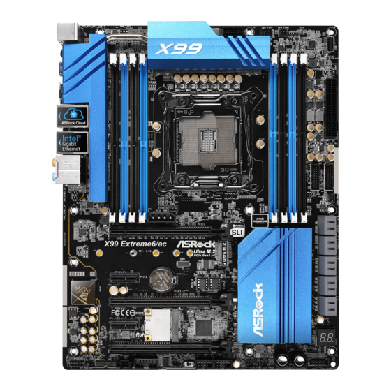
Seite 3: Motherboard-Layout
X99 Extreme6 Motherboard Layout CPU_FAN1 CPU_FAN2 ATX12V1 USB7 CLRC BTN1 USB 3.0 T: USB1 B: USB2 2011-3 Socket USB 3.0 Top: T: USB1 RJ-45 B: USB2 USB 3.0 Top: T: USB3 RJ-45 B: USB4 PCIE_PWR1 CHA_FAN3 PWR_FAN1 PCIE1 X99 Extreme6 Ultra M.2... - Seite 4 No. Description 2 x 284-pin DDR4 DIMM Slots (DDR4_A1, DDR4_B1) 2 x 284-pin DDR4 DIMM Slots (DDR4_A2, DDR4_B2) ATX 12V Power Connector (ATX12V1) CPU Fan Connector (CPU_FAN1) 2 x 284-pin DDR4 DIMM Slots (DDR4_D2, DDR4_C2) CPU Fan Connector (CPU_FAN2) 2 x 284-pin DDR4 DIMM Slots (DDR4_D1, DDR4_C1) Vertical Type A USB 2.0 (USB7) ATX Power Connector (ATXPWR1) USB 3.0 Header (USB3_7_8)
- Seite 5 X99 Extreme6 No. Description PCIe Power Connector (PCIE_PWR1) Power Fan Connector (PWR_FAN1) Downloaded from www.Manualslib.com manuals search engine...
- Seite 6 1.4 I/O Panel No. Description No. Description USB 2.0 Ports (USB12) Optical SPDIF Out Port LAN RJ-45 Port USB 3.0 Ports (USB3_34) (Qualcomm® Atheros® AR8171)* (ASMedia ASM1074 hub) LAN RJ-45 Port USB 3.0 Ports (USB3_12) (Intel® I218V)* (ASMedia ASM1074 hub) Central / Bass (Orange) eSATA Connector*** Rear Speaker (Black)
- Seite 7 X99 Extreme6 * here are two LEDs on each LAN port. Please refer to the table below for the LAN port LED indications. ACT/LINK LED SPEED LED LAN Port Activity / Link LED Speed LED Status Description Status Description No Link...
-
Seite 8: Package Contents
If you require technical support related to this mother- board, please visit our website for speciic information about the model you are using. You may ind the latest VGA cards and CPU support list on ASRock’s website as well. ASRock website http://www.asrock.com. - Seite 9 • 8 x DDR4 DIMM Slots • Supports DDR4 3000+(OC)*/2933+(OC)/2800(OC)/2400 (OC)/2133/1866/ 1600/1333/1066 non-ECC, un-bufered memory * Please refer to Memory Support List on ASRock's website for more information. (http://www.asrock.com/) • Supports non-ECC RDIMM (Registered DIMM) • Supports DDR4 ECC, un-bufered memory/RDIMM with Intel®...
- Seite 10 Rear Panel • 1 x Optical SPDIF Out Port • 1 x eSATA Connector • 2 x USB 2.0 Ports (Supports ESD Protection (ASRock Full Spike Protection)) • 4 x USB 3.0 Ports (ASMedia ASM1074 hub) (Supports ESD Protection (ASRock Full Spike Protection)) • 2 x USB 3.0 Ports (ASMedia ASM1042) (Supports ESD...
- Seite 11 • 10 x SATA3 6.0 Gb/s Connectors, support RAID (RAID Storage 0, RAID 1, RAID 5, RAID 10 and Intel Rapid Storage 13), NCQ, AHCI, Hot Plug and ASRock HDD Saver Technology (SSATA3_3 connector is shared with the eSATA port) (SSATA3_2 connector is shared with Ultra M.2 Socket) * RAID is supported on SATA3_0 ~ SATA3_5 ports only.
- Seite 12 Due to limitation, the actual memory size may be less than 4GB for the reservation for sys- tem usage under Windows® 32-bit operating systems. Windows® 64-bit operating systems do not have such limitations. You can use ASRock XFast RAM to utilize the memory that Windows® cannot use.
- Seite 13 X99 Extreme6 Chapter 2 Installation his is an ATX form factor motherboard. Before you install the motherboard, study the coniguration of your chassis to ensure that the motherboard its into it. Pre-installation Precautions Take note of the following precautions before you install motherboard components or change any motherboard settings.
-
Seite 14: Installing The Cpu
2.1 Installing the CPU 1. Before you insert the 2011-3-Pin CPU into the socket, please check if the PnP cap is on the socket, if the CPU surface is unclean, or if there are any bent pins in the socket. Do not force to insert the CPU into the socket if above situation is found. - Seite 15 X99 Extreme6 Downloaded from www.Manualslib.com manuals search engine...
- Seite 16 Please save and replace the cover if the processor is removed. he cover must be placed if you wish to return the motherboard for ater service. Downloaded from www.Manualslib.com manuals search engine...
- Seite 17 X99 Extreme6 2.2 Installing the CPU Fan and Heatsink Downloaded from www.Manualslib.com manuals search engine...
- Seite 18 2.3 Installation of Memory Modules (DIMM) his motherboard provides eight 284-pin DDR4 (Double Data Rate 4) DIMM slots, and supports Quad Channel Memory Technology. 1. For quad channel coniguration, you always need to install identical (the same brand, speed, size and chip-type) DDR4 DIMM pairs. 2.
- Seite 19 X99 Extreme6 Downloaded from www.Manualslib.com manuals search engine...
- Seite 20 2.4 Expansion Slots (PCI Express Slots) here are 5 PCI Express slots and 1 mini-PCI Express slot on the motherboard. Before installing an expansion card, please make sure that the power supply is switched of or the power cord is unplugged. Please read the documentation of the expansion card and make necessary hardware settings for the card before you start the installation.
- Seite 21 X99 Extreme6 PCIe Slot Conigurations (For CPU with 28 PCIe lanes) PCIE1 PCIE2 PCIE3 PCIE4 PCIE5 Single Graphics Card Two Graphics Cards in CrossFireX or SLI Mode hree Graphics Cards in 3-Way CrossFireX Mode *3-Way SLI Mode is not supported for CPU with 28 PCIe lanes.
- Seite 22 2.5 Jumpers Setup he illustration shows how jumpers are setup. When the jumper cap is placed on the pins, the jumper is “Short”. If no jumper cap is placed on the pins, the jumper is “Open”. he illustration shows a 3-pin jumper whose pin1 and pin2 are “Short” when a jumper cap is placed on these 2 pins.
- Seite 23 X99 Extreme6 2.6 Onboard Headers and Connectors Onboard headers and connectors are NOT jumpers. Do NOT place jumper caps over these headers and connectors. Placing jumper caps over the headers and connectors will cause permanent damage to the motherboard. System Panel Header...
- Seite 24 Serial ATA3 Connectors hese ten SATA3 (SSATA3_0_1: connectors support SATA see p.1, No. 13) data cables for internal (SSATA3_2_3: storage devices with up see p.1, No. 14) to 6.0 Gb/s data transfer (SATA3_0_3: rate. If the eSATA port see p.1, No. 15) on the rear I/O has been (SATA3_1_4: connected, the internal...
- Seite 25 X99 Extreme6 Front Panel Audio Header his header is for PRESENCE# MIC_RET (9-pin HD_AUDIO1) connecting audio devices OUT_RET (see p.1, No. 33) to the front audio panel. OUT2_L J_SENSE OUT2_R MIC2_R MIC2_L 1. High Deinition Audio supports Jack Sensing, but the panel wire on the chassis must sup- port HDA to function correctly.
- Seite 26 CPU Fan Connectors his motherboard pro- (4-pin CPU_FAN1) vides a 4-Pin CPU fan (see p.1, No. 4) (Quiet Fan) connector. +12V If you plan to connect a CPU_F AN_SPEED FAN_SPEED_CONTROL 3-Pin CPU fan, please (3-pin CPU_FAN2) connect it to Pin 1-3. (see p.1, No.
- Seite 27 X99 Extreme6 RRXD1 Serial Port Header his COM1 header DDTR#1 DDSR#1 (9-pin COM1) supports a serial port CCTS#1 (see p.1, No. 30) module. RRI#1 RRTS#1 TTXD1 DDCD#1 TPM Header his connector supports Trusted (17-pin TPMS1) Platform Module (TPM) system, (see p.1, No. 32)
-
Seite 28: Smart Switches
2.7 Smart Switches he motherboard has four smart switches: Power Switch, Reset Switch, Clear CMOS Switch and one BIOS Selection Switch, allowing users to quickly turn on/of the system, reset the system, clear the CMOS values or boot from diferent BIOS. Power Switch Power Switch allows users Power... - Seite 29 X99 Extreme6 2.8 Dr. Debug Dr. Debug is used to provide code information, which makes troubleshooting even easier. Please see the diagrams below for reading the Dr. Debug codes. Code Description Please check if the CPU is installed correctly and then clear CMOS.
- Seite 30 Problem related to USB devices. Please try removing all USB devices. Problem related to memory. Please re-install the CPU and memory then clear CMOS. If the problem still exists, please install only one memory module or try using other memory modules.
- Seite 31 X99 Extreme6 2.9 M.2_SSD (NGFF) Module Installation Guide he M.2, also known as the Next Generation Form Factor (NGFF), is a small size and versatile card edge connector that aims to replace mPCIe and mSATA. he Ultra M.2 Socket (M2) can accommodate either a M.2 SATA3 6.0 Gb/s module or a M.2 PCI Express module up to Gen3 x4 (32 Gb/s).
- Seite 32 Step 3 Move the standof based on the module type and length. he standof is placed at the nut location D by default. Skip Step 3 and 4 and go straight to Step 5 if you are going to use the default nut. Otherwise, release the standof by hand.
- Seite 33 X99 Extreme6 M.2_SSD (NGFF) Module Support List PCIe Interface SATA Interface Plextor PX-G512M6e ADATA AXNS381E-128GM-B Plextor PX-G256M6e ADATA AXNS381E-256GM-B SanDisk SD6PP4M-128G Crucial CT120M500SSD4/120G SanDisk SD6PP4M-256G Crucial CT240M500SSD4/240G Samsung XP941-512G (MZHPU512HCGL) Intel SSDSCKGW080A401/80G Kingston RBU-SM2280S3/120G For the latest updates of M.2_SSD (NFGG) module support list, please visit our website for details: http://www.asrock.com...
-
Seite 34: Connection Diagram
2.10 HDD Saver Cable Installation Guide The HDD Saver Connector on this motherboard allows you to switch on and off the connected HDDs via sotware when needed. his design secures more privacy, saves more energy, and extends the HDDs' lifespans. Please follow the steps below to install the HDD Saver Cable. -
Seite 35: Einleitung
X99 Extreme6 1 Einleitung Vielen Dank, dass Sie sich für das X99 Extreme6 von ASRock entschieden haben – ein zuverlässiges Motherboard, das konsequent unter der strengen Qualitätskontrolle von ASRock hergestellt wurde. Es liefert ausgezeichnete Leistung mit robustem Design, das ASRocks Streben nach Qualität und Beständigkeit erfüllt. -
Seite 36: Technische Daten
• Unterstützt DDR4 3000+(OC)*/2933+(OC)/2800(OC)/2400 (OC)/2133/1866/1600/1333/1066 non-ECC, ungepuferter Speicher * Weitere Informationen inden Sie in der Speicherkompatibilitätsliste auf der ASRock-Webseite. (http:// www.asrock.com/) • Unterstützt ECC-lose RDIMM (Registered-DIMM) • Unterstützt DDR4 ECC, ungepuferter Speicher/RDIMM mit Intel® Xeon®-Prozessoren der E5-Serie im LGA 2011-3-Sockel • Systemspeicher, max. - Seite 37 • 2 x USB 2.0-Port (unterstützt Schutz gegen elektrostatische Entladung (ASRock Full Spike Protection)) • 4 x USB 3.0-Ports (ASMedia ASM1074-Hub) (unterstützt Schutz gegen elektrostatische Entladung (ASRock Full Spike Protection)) • 2 x USB 3.0-Ports (ASMedia ASM1042) (unterstützt Schutz gegen elektrostatische Entladung (ASRock Full Spike...
-
Seite 38: Anschluss
• 1 x Audioanschluss an Frontblende • 1 x hunderbolt-Erweiterungskartenanschluss • 2 x USB 2.0-Stitleisten (unterstützen 4 USB 2.0-Ports) (un- terstützt Schutz gegen elektrostatische Entladung (ASRock Full Spike Protection)) • 1 x Vertikal, Typ A, USB 2.0 • 2 x USB 3.0-Stitleisten (unterstützen 4 USB 3.0-Ports) (unterstützt Schutz gegen elektrostatische Entladung (AS-... -
Seite 39: Funktion
Aufgrund von Beschränkungen kann die Größe des tatsächlich für die Systemnutzung reservierten Speichers unter Windows®-Betriebssystemen mit 32 Bit weniger als 4 GB betra- gen. Windows®-Betriebssysteme mit 64 Bit haben keine derartigen Beschränkungen. Mit ASRock XFast RAM können Sie den Speicher einsetzen, den Windows® nicht nutzen kann. Downloaded from www.Manualslib.com... -
Seite 40: Jumpereinstellung
1.3 Jumpereinstellung Die Abbildung zeigt, wie die Jumper eingestellt werden. Wenn die Jumper- Kappe auf den Kontakten angebracht ist, ist der Jumper „kurzgeschlossen“. Wenn keine Jumper-Kappe auf den Kontakten angebracht ist, ist der Jumper „ofen“. Die Abbildung zeigt einen 3-poligen Jumper, dessen Kontakt 1 und Kontakt 2 „kurzgeschlossen“... -
Seite 41: Integrierte Stiftleisten Und Anschlüsse
X99 Extreme6 1.4 Integrierte Stiftleisten und Anschlüsse Integrierte Stitleisten und Anschlüsse sind KEINE Jumper. Bringen Sie KEINE Jumper- Kappen an diesen Stitleisten und Anschlüssen an. Durch Anbringen von Jumper-Kappen an diesen Stitleisten und Anschlüssen können Sie das Motherboard dauerhat beschädi- gen. - Seite 42 Betrieb-LED-Stitleiste Bitte verbinden Sie (3-polig, PLED1) die Betrieb-LED des PLED- PLED+ (siehe S. 1, Nr. 18) Gehäuses zur Anzeige des PLED+ Systembetriebsstatus mit dieser Stitleiste. Serial-ATA-III- Diese zehn SATA-III- Anschlüsse Anschlüsse unterstützen (SSATA3_0_1: SATA-Datenkabel für siehe S. 1, Nr. 13) interne Speichergeräte (SSATA3_2_3: mit einer Datenübertr...
- Seite 43 X99 Extreme6 USB 3.0-Stitleisten Neben sechs USB Vbus Vbus Vbus IntA_PB_SSRX- (19-polig, USB3_5_6) 3.0-Ports an der E/ IntA_PA_SSRX- IntA_PB_SSRX+ (siehe S. 1, Nr. 11) IntA_PA_SSRX+ A-Blende beindet sich IntA_PB_SSTX- (19-polig, USB3_7_8) zwei Stitleiste an diesem IntA_PA_SSTX- IntA_PB_SSTX+ IntA_PA_SSTX+ (siehe S. 1, Nr. 10) Motherboard.
- Seite 44 (3-polig, CHA_FAN3) FAN_VOLTAGE (siehe S. 1, Nr. 12) CHA_FAN_SPEED (3-polig, PWR_FAN1) (siehe S. 1, Nr. 35) CPU-Lüteranschlüsse Dieses Motherboard bietet (4-polig, CPU_FAN1) einen 4-poligen CPU- (siehe S. 1, Nr. 4) Lüteranschluss (lautloser +12V Lüter). Falls Sie einen CPU_F AN_SPEED (3-polig, CPU_FAN2) FAN_SPEED_CONTROL 3-poligen CPU-Lüter (siehe S.
- Seite 45 X99 Extreme6 HDD-Saver-Anschluss Bitte verbinden Sie zum (4-polig, SATA_PWR_1) Verwalten des Energiestatus der (siehe S. 1, Nr. 22) Festplatte das HDD-Saver-Kabel mit diesem Anschluss. hunderbolt- Bitte verbinden Sie ein serielles Erweiterungskar- 5-poliges Kabel (GPIO- tenanschluss Kabel) mit diesem Anschluss, (5-polig, TBT1) wenn Sie eine hunderbolt™-...
- Seite 46 1.5 Intelligente Schalter Das Motherboard hat vier intelligente Schalter: Ein-/Ausschalter, Reset-Schalter, CMOS-löschen-Schalter und ein BIOS-Auswahlschalter, wodurch Benutzer das System schnell ein-/abschalten, zurücksetzen, die CMOS-Werte löschen oder von einem anderen BIOS starten können. Ein-/Ausschalter Mit dem Ein-/Ausschalter (PWRBTN) kann der Benutzer das Power (siehe S.
-
Seite 47: Contenu De L'emballage
à modiication sans préavis. En cas de modiications du présent document, la version mise à jour sera disponible sur le site Internet ASRock sans notiication préalable. Si vous avez besoin d’une assistance technique pour votre carte mère, veuillez visiter notre site Internet pour plus de détails sur le modèle que vous utilisez. - Seite 48 * Veuillez consulter la liste de prise en charge des mémoires sur le site Web d' A SRock pour de plus amples informations. (http:// www.asrock.com/) • Prend en charge RDIMM non-ECC (RDIMM enregistrée) • Prend en charge DDR4 ECC, la mémoire sans mise en tampon/RDIMM avec la série de processeurs Intel®...
- Seite 49 Wake On Internet (sur Qualcomm® Atheros® AR8171) • Prend en charge la fonction Wake-On-LAN • Protection contre les orages/décharges électrostatiques (Pro- tection complète contre les pics ASRock) • Prend en charge la fonction d’économie d’énergie Ethernet 802.3az • Prend en charge PXE • 1 x port souris/clavier PS/2...
- Seite 50 • 2 x embases USB 2.0 (4 ports USB 2.0 pris en charge) (Pro- tection contre les décharges électrostatiques (Protection complète contre les pics ASRock)) • 1 x USB 2.0 type A vertical • 2 x embases USB 3.0 (4 ports USB 3.0 pris en charge) (Pro- tection contre les décharges électrostatiques (Protection...
- Seite 51 • ErP/EuP Ready (alimentation ErP/EuP ready requise) tions * pour des informations détaillées de nos produits, veuillez visiter notre site : http://www.asrock.com Il est important de signaler que l'overcloking présente certains risques, incluant des modiications du BIOS, l’application d’une technologie d’overclocking déliée et l'utilisation d'outils d'overclocking développés par des tiers.
- Seite 52 1.3 Coniguration des cavaliers (jumpers) L’illustration ci-dessous vous renseigne sur la coniguration des cavaliers (jumpers). Lorsque le capuchon du cavalier est installé sur les broches, le cavalier est « court- circuité ». Si le capuchon du cavalier n’est pas installé sur les broches, le cavalier est « ouvert ».
- Seite 53 X99 Extreme6 1.4 Embases et connecteurs de la carte mère Les embases et connecteurs situés sur la carte NE SONT PAS des cavaliers. Ne placez JAMAIS de capuchons de cavaliers sur ces embases ou connecteurs. Placer un capuchon de cavalier sur ces embases ou connecteurs endommagera irrémédiablement votre carte mère.
- Seite 54 Connecteurs Serial ATA3 Ces dix connecteurs (SSATA3_0_1: SATA3 sont compatibles (voir p.1, No. 13) avec les câbles de données (SSATA3_2_3: SATA pour les appareils voir p.1, No. 14) de stockage internes (SATA3_0_3: avec un taux de transfert (voir p.1, No. 15) maximal de 6,0 Go/s.
-
Seite 55: Inhaltsverzeichnis
X99 Extreme6 Embase audio du panneau Cette embase sert au PRESENCE# frontal branchement des appareils MIC_RET (HD_AUDIO1 à 9 OUT_RET audio au panneau audio broches) frontal. (voir p.1, No. 33) OUT2_L J_SENSE OUT2_R MIC2_R MIC2_L 1. L’audio haute déinition prend en charge la technologie Jack Sensing (détection de la iche), mais le panneau grillagé... -
Seite 56: Broches) (Voir P.1, No. 33)
Connecteurs du Cette carte mère est dotée ventilateur du processeur d’un connecteur pour (CPU_FAN1 à 4 broches) ventilateur de processeur (voir p.1, No. 4) (Quiet Fan) à 4 broch- +12V es. Si vous envisagez de CPU_F AN_SPEED FAN_SPEED_CONTROL connecter un ventilateur de processeur à... - Seite 57 X99 Extreme6 Connecteur hunderbolt Veuillez connecter un câble de signal à 5 broches (câble GPIO) (TBT1 à 5 broches) à ce connecteur lorsque vous (voir p.1, No. 31) utilisez une carte d'extension hunderbolt™ (AIC). RRXD1 Embase pour port série Cette embase COM1...
- Seite 58 1.5 Boutons intelligents La carte mère est équipée de quatre boutons intelligents : bouton de mise en marche, bouton de réinitialisation, bouton d’efacement CMOS et bouton de sélecteur de BIOS qui permettent aux utilisateurs d’allumer/éteindre le système, de réinitialiser le système, d’efacer les valeurs CMOS en toute simplicité ou de démarrer depuis un BIOS diférent.
-
Seite 59: Contenuto Della Confezione
Nel caso di eventuali modiiche della presente documentazione, la versione aggiornata sarà disponi- bile sul sito Web di ASRock senza ulteriore preavviso. Per il supporto tecnico correlato a questa scheda madre, visitare il nostro sito Web per informazioni speciiche relative al modello attualmente in uso. -
Seite 60: Speciiche
• Supporto di memoria DDR4 3000+(OC)*/2933+(OC)/2800 (OC)/2400(OC)/2133/1866/1600/1333/1066 non-ECC, un- bufered * Per maggiori informazioni fare riferimento all'elenco dei supporti di memoria sul sito di ASRock. (http://www.asrock. com/) • Supporta RDIMM non ECC (DIMM registrato) • Supporta memoria/RDIMM DDR4 ECC, senza bufer con processori Intel®... - Seite 61 On Internet Technology (su Qualcomm® Atheros® AR8171) • Supporta Wake-On-LAN • Supporto la protezione da fulmini/scariche elettrostatiche (ESD) (protezione completa ASRock dai picchi di corrente) • Supporta Energy Eicient Ethernet 802.3az • Supporta PXE • 1 x porta mouse/tastiera PS/2 I/O pan- • 1 x porta uscita SPDIF ottico...
- Seite 62 • 2 x Collettori USB 2.0 (supporto di 4 porte 4 USB 3.0) (sup- porto protezione da scariche elettrostatiche (ESD) (protezi- one completa ASRock dai picchi di corrente)) • 1 x USB 2.0 verticale tipo A • 2 x Collettori USB 3.0 (supporto di 4 porte 4 USB 3.0)
- Seite 63 • ErP/EuP Ready (è necessaria alimentazione ErP/EuP ready) zioni * Per informazioni dettagliate sul prodotto, visitare il nostro sito Web: http://www.asrock.com Prestare attenzione al potenziale rischio previsto nella pratica di overclocking, inclusa la regolazione delle impostazioni nel BIOS, l'applicazione di tecnologia di Untied Overclock- ing o l'utilizzo di strumenti di overclocking di terze parti.
- Seite 64 1.3 Impostazione jumper L'illustrazione mostra in che modo vengono impostati i jumper. Quando il cappuccio del jumper è posizionato sui pin, il jumper è "cortocircuitato". Se sui pin non è posizionato alcun cappuccio del jumper, il jumper è "aperto". L'illustrazione mostra un jumper a 3 pin i cui pin1 e pin2 sono "cortocircuitati"...
- Seite 65 X99 Extreme6 1.4 Header e connettori sulla scheda Gli header e i connettori sulla scheda NON sono jumper. NON posizionare cappucci del jumper su questi header e connettori. Il posizionamento di cappucci del jumper su header e connettori provocherà danni permanenti alla scheda madre.
- Seite 66 Header LED di Collegare il LED di alimentazione alimentazione chassis a PLED- PLED+ (PLED1 a 3 pin) questo header per indicare PLED+ (vedere pag. 1, n. 18) lo stato di alimentazione del sistema. Connettori Serial ATA3 Questi dieci connettori (SSATA3_0_1: SATA3 supportano cavi vedere pag.
-
Seite 67: Gnd Presence# Mic_Ret
X99 Extreme6 Header audio pannello Questo header serve a PRESENCE# anteriore collegare i dispositivi MIC_RET OUT_RET (AUDIO1_HD a 9 pin) audio al pannello audio (vedere pag. 1, n. 33) anteriore. OUT2_L J_SENSE OUT2_R MIC2_R MIC2_L 1. L'audio ad alta deinizione supporta le funzioni Jack sensing, ma il ilo del pannello sullo chassis deve supportare HDA per funzionare correttamente. -
Seite 68: Fan_Speed_Control
Connettori della ventola Questa scheda madre è della CPU dotata di un connettore (CPU_FAN1 a 4 pin) per la ventola della CPU +12V (vedere pag. 1, n. 4) (Ventola silenziosa) a CPU_F AN_SPEED 4 pin. Se si decide di FAN_SPEED_CONTROL (CPU_FAN2 a 3 pin) collegare una ventola della (vedere pag. - Seite 69 X99 Extreme6 RRXD1 Header porta seriale Questo header COM1 DDTR#1 DDSR#1 (COM1 a 9 pin) supporta un modulo di CCTS#1 (vedere pag. 1, n. 30) porta seriale. RRI#1 RRTS#1 TTXD1 DDCD#1 Header TPM Questo connettore supporta il (TPMS1 a 17 pin) sistema Trusted Platform Module (vedere pag.
- Seite 70 1.5 Interruttori intuitivi La scheda madre è dotata di quattro interruttori intuitivi: Interruttore d’alimentazione, interruttore di ripristino, interruttore Clear CMOS ed un interruttore di selezione BIOS che consentono di accendere/spegnere rapidamente il sistema, ripristinare il sistema, cancellare i valori CMOS oppure eseguire l’avvio su un BIOS diverso.
-
Seite 71: Contenido Del Paquete
Podrá encontrar las últimas tarjetas VGA, así como la lista de compatibilidad de la CPU, en el sitio web de ASRock. Sitio web de ASRock http://www. asrock.com. - Seite 72 • Compatible con memoria no-ECC, sin búfer DDR4 3000+(OC)*/2933+(OC)/2800(OC)/2400(OC)/ 2133/1866/1600/1333/1066 * Para obtener más información, consulte la lista de memorias compatibles en el sitio web de ASRock. (http://www.asrock. com/) • Admite RDIMM no ECC (DIMM registrado) • Admite ECC DDR4, memoria sin búfer/RDIMM con procesadores Intel®...
- Seite 73 • 1 puerto de salida SPDIF óptica trasero I/O • 1 conector eSATA • 2 puerto USB 2.0 (compatible con protección contra electricidad estática (protección ASRock Full Spike)) • 4 puertos USB 3.0 (concentrador ASMedia ASM1074AE) (compatible con protección contra electricidad estática (protección ASRock Full Spike)) • 2 puertos USB 3.0 (ASMedia ASM1042) (compatible con...
- Seite 74 RAID (RAID 0, RAID 1, RAID 5, RAID 10, Intel namiento Rapid Storage Technology 13), NCQ, AHCI y conexión en caliente y tecnología de ahorro ASRock HDD (el conector SSATA3_3 se comparte con el puerto eSATA) (el conector SSATA3_2 se comparte con el puerto Ultra M.2...
- Seite 75 ErP/EuP) * Para obtener más información acerca del producto, visite nuestro sitio web: http://www.asrock.com Tenga en cuenta que existen ciertos riesgos relacionados con el overclocking (sobreacel- eración), incluyendo el ajuste de la coniguración del BIOS, aplicando la Tecnología overcloking no vinculada o utilizando las herramientas de overclocking de tercera parte.
- Seite 76 1.3 Instalación de los puentes La instalación muestra cómo deben instalarse los puentes. Cuando la tapa de puente se coloca en los pines, el puente queda “Corto”. Si no coloca la tapa de puente en los pines, el puente queda “Abierto”. La ilustración muestra un puente de 3 pines cuyo pin 1 y pin 2 son “Cortos”...
- Seite 77 X99 Extreme6 1.4 Conectores y cabezales incorporados Los cabezales y conectores incorporados NO son puentes. NO coloque tapas de puente sobre estos cabezales y conectores. Si coloca tapas de puente sobre los cabezales y conectores dañará de forma permanente la placa base.
- Seite 78 Cabezal de indicador LED Conecte el indicador LED de alimentación de alimentación del chasis PLED- PLED+ (PLED1 de 3 pines) a este cabezal para indicar PLED+ (consulte la pág.1, N.º 18) el estado de alimentación del sistema. Conectores Serie ATA3 Estos diez conectores (SSATA3_0_1: SATA3 son compatibles...
- Seite 79 X99 Extreme6 Cabezal de audio del Este cabezal se utiliza PRESENCE# panel frontal para conectar dispositivos MIC_RET OUT_RET (HD_AUDIO1 de 9 pines) de audio al panel de audio (consulte la pág.1, N.º 33) frontal. OUT2_L J_SENSE OUT2_R MIC2_R MIC2_L 1. El Audio de Alta Deinición (HDA, en inglés) es compatible con el método de sensor de conectores, sin embargo, el cable del panel del chasis deberá...
- Seite 80 Conectores del ventilador Esta placa base contiene de la CPU un conector de ventilador (CPU_FAN1 de 4 pines) (ventilador silencioso) de (consulte la pág.1, N.º 4) CPU de 4 pines. Si tiene +12V CPU_F AN_SPEED pensando conectar un FAN_SPEED_CONTROL ventilador de CPU de 3 (CPU_FAN2 de 3 pines) pines, conéctelo al Pin 1-3.
- Seite 81 X99 Extreme6 Cabezal de puerto serie Este cabezal COM1 RRXD1 DDTR#1 DDSR#1 (COM1 de 9 pines) admite un módulo de CCTS#1 (consulte la pág.1, N.º 30) puerto serie. RRI#1 RRTS#1 TTXD1 DDCD#1 Cabezal TPM Este conector es compatible con (TPMS1 de 17 pines) el sistema Módulo de Plataforma...
- Seite 82 1.5 Interruptores inteligentes La placa base contiene cuatro interruptores inteligentes: Interruptor de alimentación, interruptor de reseteo, interruptor de borrado de CMOS y un interruptor de selección BIOS, que permiten a los usuarios encender y apagar rápidamente el sistema, resetearlo, borrar los valores de CMOS, o arrancar desde un BIOS diferente.
-
Seite 83: Комплект Поставки
уведомления. При необходимости технической поддержки, связанной с материнской платой, посетите веб-сайт и найдите на нем информацию о модели используемой вами материнской платы. На веб-сайте ASRock также можно найти самый последний перечень поддерживаемых VGA-карт и ЦП. Веб-сайт ASRock http://www.asrock.com. 1.1 Комплект поставки... - Seite 84 (OC)/2800(OC)/2400(OC)/ 2133/1866/ 1600/1333/1066 Non-ECC Unbufered * Дополнительная информация представлена в Списке совместимой памяти (Memory Support List ) на веб-сайте ASRock. (http://www.asrock.com/) • Поддержка RDIMM без ЕСС (Регистровая память DIMM) • Поддержка DDR4 ECC, небуферизованной памяти/ RDIMM с процессорами Intel® Xeon® серии E5 в LGA 2011-3 Socket • Максимальный...
- Seite 85 • 7.1-канальный звук высокой четкости HD Audio с Аудио защитой данных (аудиокодек Realtek ALC1150) • Поддержка Premium Blu-ray Audio • Защита от перенапряжения (ASRock Full Spike Protection) • Поддержка Purity Sound™ 2 - Конденсаторы для аудиосистем серии Nichicon Fine Gold - 115 дБ...
- Seite 86 6,0 ГБ/с с Intel® X99, технологии RAID (RAID 0, RAID устройства 1, RAID 5, RAID 10, Intel Rapid Storage Technology 13), NCQ, AHCI, "горячего" подключения и ASRock HDD Saver (разъем SSATA3_3 используется с портом eSATA) (разъем SSATA3_2 используется с портом Ultra M.2 Socket) * Поддержка...
- Seite 87 В связи с ограничением при работе под 32-разрядной ОС Windows® фактический объем памяти может быть меньше 4 Гбайт. Для 64-разрядных ОС Windows® таких ограничений нет. Для использования той памяти, которую ОС Windows® не может использовать, используйте ASRock XFast RAM. Downloaded from www.Manualslib.com...
- Seite 88 1.3 Установка перемычек Установка перемычек показана на рисунке. При установке колпачковой перемычки на контакты перемычка «замкнута». Если колпачковая перемычка на контакты не установлена, перемычка «разомкнута». На рисунке показана 3-контактная перемычка с замкнутыми контактами 1 и 2 при установке на них колпачковой...
- Seite 89 X99 Extreme6 1.4 Колодки и разъемы, расположенные на материнской плате Расположенные на материнской плате колодки и разъемы перемычками НЕ являются. НЕ устанавливайте на эти колодки и разъемы колпачковые перемычки. Установка колпачковых перемычек на эти колодки и разъемы может вызвать неустранимое...
- Seite 90 Разъемы Serial ATA3 Эти десять разъемов (SSATA3_0_1: SATA3 предназначены для См. стр. 1, № 13) подключения кабелей SATA (SSATA3_2_3: внутренних запоминающих см. стр. 1, № 14) устройств для передачи (SATA3_0_3: данных со скоростью до 6,0 См. стр. 1, № 15) Гб/с.
- Seite 91 X99 Extreme6 Аудиоколодка передней Эта колодка предназначена для PRESENCE# панели подключения аудиоустройств MIC_RET OUT_RET (9-контактная, HD_ к передней аудиопанели. AUDIO1) (См. стр. 1, № 33) OUT2_L J_SENSE OUT2_R MIC2_R MIC2_L 1. Аудиосистема высокого разрешения поддерживает функцию распознавания разъема, но для е правильной работы необходимо, чтобы провод панели корпуса поддерживал...
- Seite 92 Разъемы вентиляторов Эта материнская плата ЦП снабжена 4-контактным (4-контактный, CPU_ разъемом для малошумящего FAN1) вентилятора ЦП. Если вы +12V (См. стр. 1, № 4) собираетесь подключить CPU_F AN_SPEED FAN_SPEED_CONTROL 3-контактный вентилятор (3-контактный, CPU_ охлаждения процессора, FAN2) подключайте его к контактам (См.
- Seite 93 X99 Extreme6 Колодка RRXD1 Колодка COM1 поддерживает DDTR#1 DDSR#1 последовательного порта подключение модуля CCTS#1 (9-контактная, COM1) последовательного порта. (См. стр. 1, № 30) RRI#1 RRTS#1 TTXD1 DDCD#1 Колодка ТРМ Этот разъем обеспечивает поддержку (17-контактная, TPMS1) системы Trusted Platform Mod- (См. стр. 1, № 32) ule (TPM), которая...
- Seite 94 1.5 Электронные кнопки На системной плате размещены четыре электронных переключателя: выключатель питания, кнопка сброса, кнопка очистки КМОП и селекторный переключатель BIOS, позволяющие быстро выключать/выключать систему, сбрасывать систему, очищать параметры КМОП или загружаться с другой BIOS. Кнопка питания Кнопка питания (PWRBTN) предназначена...
-
Seite 95: Conteúdo Da Embalagem
Se precisar de assistência técnica relacionada a esta placa principal, visite o nosso site para obter informações especíicas sobre o modelo que estiver utilizando. Você também poderá encontrar a lista de placas VGA e CPU mais recentes suportadas no site da ASRock. Site da ASRock http://www.asrock.com. - Seite 96 (OC)/2400(OC)/ 2133/1866/1600/1333/1066, não ECC, sem memória intermediária * Por favor, consulte a Lista de Suporte de Memória no site da ASRock para obter mais informação. (http://www.asrock.com/) • Suporta RDIMM não ECC (DIMM registrada) • Suporta DDR4 ECC, memória não armazenamento/RDIMM com processadores Intel ®...
- Seite 97 X99 Extreme6 • 1 x mini-PCI Express Slot • Suporta AMD Quad CrossFireX , 3-Way CrossFireX CrossFireX • Suporta Quad SLI , 3-Way SLI e SLI da NVIDIA® *Se você instalar CPU com 28 vias, o 3-Way SLI não é...
- Seite 98 • 4 x Portas USB 3.0 (ASMedia ASM1074 núcleo)(Suporta Proteção ESD (Proteção Total Contra Picos ASRock)) • 2 x Portas USB 3.0 (ASMedia ASM1042)(Suporta Proteção ESD (Proteção Total Contra Picos ASRock)) • 2 x Porta LAN RJ-45 com LED (LED ACT/LIGAÇÃO e LED DE VELOCIDADE) • 1 Interruptor para apagar o CMOS...
- Seite 99 • FCC, CE, WHQL Certii- • Preparada para ErP/EuP (é necessária uma fonte de alimen- cações tação preparada para ErP/EuP) * Para obter informações detalhadas sobre o produto, por favor, visite o nosso site: http://www.asrock.com Downloaded from www.Manualslib.com manuals search engine...
- Seite 100 Devido às limitações, o tamanho real da memória pode ser menor que 4GB para a reserva de uso do sistema nos sistemas operacionais Windows® 32-bits. Os sistemas operacionais Win- dows® 64-bits não possuem estas limitações. Pode utilizar o ASRock XFast RAM para utilizar a memória que o Windows® não utiliza.
- Seite 101 X99 Extreme6 1.3 Coniguração dos jumpers A imagem abaixo mostra como os jumpers são conigurados. Quando a tampa do jumper é colocada nos pinos, o jumper é "Curto". Se não for colocada uma tampa de jumper nos pinos, o jumper é "Aberto". A imagem mostra um jumper de 3 pinos cujos pino1 e pino2 estão "Curtos"...
- Seite 102 1.4 Suportes e conectores onboard Os conectores e suportes onboard NÃO são jumpers. NÃO coloque tampas de jumpers sobre es- tes terminais e conectores Colocar tampas de jumpers sobre os terminais e conectores irá causar danos permanentes à placa-mãe. Suporte do painel de siste- Ligue o botão de PLED+ PLED-...
- Seite 103 X99 Extreme6 Conectores série ATA3 Estes dez conectores (SSATA3_0_1: SATA3 suportam (ver pág.1 No. 13) cabos de dados SATA (SSATA3_2_3: para dispositivos de (ver pág.1 No. 14) armazenamento interno (SATA3_0_3: com uma taxa de (ver pág.1 No. 15) transferência de dados de (SATA3_1_4: até...
- Seite 104 PRESENCE# Suporte de áudio do painel Este suporte destina-se à MIC_RET frontal OUT_RET conexão dos dispositivos (HD_AUDIO1 de 9 pinos) de áudio no painel de (ver p.1, N.º 33) áudio frontal. OUT2_L J_SENSE OUT2_R MIC2_R MIC2_L 1. O Áudio de alta deinição suporta Sensor de Adaptador, mas o io do painel no chassi deverá suportar HDA para funcionar corretamente.
- Seite 105 X99 Extreme6 Conectores do ventilador Esta placa mãe inclui um da CPU conector de ventilador (CPU_FAN1 de 4 pinos) da CPU (Ventilador +12V (ver p.1, N.º 4) silencioso) de 4 pinos. Se CPU_F AN_SPEED você pretende conectar um FAN_SPEED_CONTROL (CPU_FAN2 de 3 pinos) ventilador da CPU de 3 (ver p.1, N.º...
- Seite 106 Suporte da porta serial Este suporte COM1 recebe RRXD1 DDTR#1 (COM1 de 9 pinos) um módulo da porta serial. DDSR#1 CCTS#1 (ver p.1, N.º 30) RRI#1 RRTS#1 TTXD1 DDCD#1 Suporte TPM Este conector suporta um sistema (TPMS1 de 17 pinos) com Módulo de Plataforma Con- (ver p.1, N.º...
- Seite 107 X99 Extreme6 1.5 Interruptores inteligentes A placa-mãe tem quatro chaves inteligentes: Chave liga/desliga, Chave de Reset, Chave para Limpar CMOS e uma Chave de Seleção da BIOS, que permite aos usuários rapidamente ligar/desligar o sistema, reiniciar o sistema, limpar os valores de CMOS ou inicializar de BIOS diferentes.
-
Seite 108: Ambalaj İçeriği
Rock'ın web sitesinde yer alacaktır.. Bu anakart ile ilgili olarak teknik destek almak istiyorsanız, lütfen kullandığınız model hakkında özel bilgiler için web sitemizi ziyaret edin. En güncel VGA kartları ve CPU destek listelerini de ASRock'ın web sitesinden bulabilirsiniz. ASRock web sitesi http://www.asrock.com. - Seite 109 • ECC olmayan, ara belleğe alınmamış DDR4 3000+(OC)*/ 2933+(OC)/2800(OC)/2400(OC)/ 2133/1866/1600/1333/1066 belleği destekler * Ayrıntılı bilgi için ASRock'ın web sitesindeki Bellek Desteği Listesine bakın. (http://www.asrock.com/) • ECC-dışı RDIMM Desteği (Kayıtlı DIMM) • DDR4 ECC, LGA 2011-3 Sokette Intel® Xeon® iºlemci E5 serisi ile birlikte ara belleksiz bellek /RDIMM desteği...
- Seite 110 Arka Panel • 1 x Optik SPDIF Çıkış Yuvası • 1 x eSATA Konektörü • 2 x USB 2.0 Yuvası (ESD Korumasını destekler (ASRock Full Spike Koruma)) • 4 x USB 3.0 Yuvaları (ASMedia ASM1074 göbeği) (ESD Korumasını Destekler (ASRock Full Spike Koruması)) • 2 x USB 3.0 Yuvaları...
- Seite 111 • 10 x SATA3 6,0 Gb/s Bağlayıcısı, RAID (RAID 0, RAID 1, Depolama RAID 5, RAID 10, Intel Rapid Storage Technology 13), NCQ, AHCI, Tak Çıkar ve ASRock Sabit Disk Kaydedici Teknolojisi destekler (SSATA3_3 bağlayıcısı eSATA bağlantı noktasıyla paylaşılır) (SSATA3_2 bağlayıcısı Ultra M.2 Socket bağlantı noktasıyla paylaşılır)
- Seite 112 • ErP/EuP için hazır (ErP/EuP için hazır güç beslemesi gerek- lidir) * Detaylı ürün bilgisi için, lütfen web sitemizi ziyaret edin: http://www.asrock.com Lütfen, BIOS ayarlarını düzenleme, Bağımsız Hız Aşırtma Teknolojinin uygulanması ya da üçüncü kişilerin hız aşırtma araçlarının kullanılması da dahil olmak üzere tüm hız aşırtma işlemlerinin belirli bir risk taşıdığını...
- Seite 113 X99 Extreme6 1.3 Bağlantı Teli Kurulumu Çizim, bağlantı tellerinin kurulumunu göstermektedir. Tel kapağı, pimlerin üzerine yerleştirildiğinde, tel "Kısa" olur. Pimlerin üzerinde tel kapağı bulunmadığında, tel "Kısa" olur. Çizim, pin1 ve pin2 alanları "Kısa" olan ve bu iki pim üzerinde bir bağlantı...
- Seite 114 1.4 Ekli Bağlantılar ve Bağlayıcılar Ekli bağlantılar ve bağlayıcılar bağlantı teli değildir. Bağlantı teli kapaklarını bu bağlantı ve bağlayıcılar üzerine yerleştirmeyin. Bağlantı teli kapaklarının bağlantılar ile bağlayıcılar üzerine yerleştirilmesi, anakarta kalıcı hasar verebilir. Sistem Paneli Bağlantısı Güç anahtarını bağlayın, PLED+ PLED- (9-pin PANEL1) kasa üzerindeki anahtar ile...
- Seite 115 X99 Extreme6 Güç LED Bağlantısı Sistemin güç durumunun (3-pin PLED1) belirtilmesi için lütfen PLED- PLED+ PLED+ (bkz. sf.1, No. 18) güç LED'ini bu bağlantıya takın. Seri ATA3 Bağlayıcıları Bu on SATA3 bağlayıcısı, (SSATA3_0_1: veri aktarım hızı 6,0 Gb/ bkz. sf.1, No. 13)
- Seite 116 USB 3.0 Bağlantıları Bu anakart üzerinde, I/O Vbus Vbus Vbus IntA_PB_SSRX- (19-pin USB3_5_6) paneli üzerindeki altı USB IntA_PA_SSRX- IntA_PB_SSRX+ IntA_PA_SSRX+ (bkz. sf.1, No. 11) 3.0 bağlantı noktasının IntA_PB_SSTX- IntA_PA_SSTX- IntA_PB_SSTX+ (19-pin USB3_7_8) yanı sıra, iki adet bağlantı IntA_PA_SSTX+ IntA_PB_D- (bkz. sf.1, No. 10) bulunmaktadır.
- Seite 117 X99 Extreme6 Kasa ve Güç Fanı Lütfen fan kablolarını +12V Bağlayıcıları CHA_FAN_SPEED fan bağlayıcılarına takın FAN_SPEED_CONTROL (4-pin CHA_FAN1) ve siyah teli topraklama (bkz sf.1, No. 25) pinine bağlayın. CHA_ FAN fan hızı UEFI veya CHA_FAN_SPEED (3-pin CHA_FAN2) A-Tuning yoluyla kontrol FAN_VOLTAGE (bkz sf.1, No.
- Seite 118 PCIe Güç Bağlayıcısı Üçten fazla graik kartı (4 pimli PCIE_PWR1) takıldığında, lütfen bu bağlayıcıya (bkz. sf.1, No. 34) bir 4 pim molex güç kablosu bağlayın. Sabit Disk Kaydedici Sabit diskin güç durumunu Bağlayıcısı yönetmek için lütfen bu (4 pimli SATA_PWR_1) bağlayıcıya Sabit Disk Kaydedici (bkz.
- Seite 119 X99 Extreme6 1.5 Akıllı Anahtar Anakartta dört adet akıllı düğme bulunur: Güç Düğmesi, Sıfırlama Düğmesi, CMOS Temizleme Düğmesi ve bir BIOS Seçim Anahtarı kullanıcıların sistemi hızlı bir şekilde açıp kapatmalarını, sistemi sıfırlamalarını, CMOS değerlerini temizlemelerini ya da farklı BIOS'tan yüklemelerini sağlar.
- Seite 120 1 개요 ASRock X99 Extreme6 마더보드를 구입해 주셔서 감사합니다 . 이 마더보드는 ASRock 의 일관되고 엄격한 품질관리 하에 생산되어 신뢰성이 우수합니다 . 품 질과 내구성에 대한 ASRock 의 기준에 부합하는 우수한 성능과 견고한 설계를 제공합니다 . 마더보드 규격과 BIOS 소프트웨어를 업데이트할 수도 있기 때문에 , 이 설명서의...
- Seite 121 • DDR4 DIMM 슬롯 8 개 • DDR4 3000+(OC)*/2933+(OC)/2800(OC)/2400(OC)/2133/ 1866/1600/1333/1066 비 -ECC, 비버퍼링 메모리 지원 * 추가 정보를 원하시면 ASRock 웹사이트에 있는 메모리 지 원 목록을 참조하십시오 . (http://www.asrock.com/) • 비 -ECC RDIMM( 등록 DIMM) 지원 • LGA 2011-3 소켓에서 버퍼링되지 않은 메모리 DDR4 ECC/Intel®...
- Seite 122 후면 패널 • 광학 SPDIF 출력 포트 1 개 • eSATA 커넥터 1 개 • USB 2.0 포트 2 개 (ESD 보호 지원 (ASRock 풀 스파이크 보 호 )) • USB 3.0 포트 4 개 (ASMedia ASM1074 허브 )(ESD 보호 지...
- Seite 123 • SATA3 6.0 Gb/s 커넥터 10 개가 RAID (RAID 0, RAID 1, 저장 장치 RAID 5, RAID 10, Intel 빠른 저장 기술 13), NCQ, AHCI, 핫 플러그 및 ASRock HDD 세이버 기술을 지원 (SSATA3_3 커넥터가 eSATA 포트와 공유됨 ) (SSATA3_2 커넥터가 Ultra M.2 Socket 포트와 공유됨 ) * RAID 는...
- Seite 124 제한 때문에 실제 메모리 크기는 Windows® 32 비트 운영체제 하의 시스템 사용을 위한 예비 메모리용 4GB 보다 더 적을 수 있습니다 . Windows® 64 비트 운영체제에는 그러 한 제한이 없습니다 . ASRock XFast RAM 을 사용하여 Windows® 가 사용할 수 없는 메 모리를 이용할 수 있습니다 .
- Seite 125 X99 Extreme6 1.3 점퍼 설정 그림은 점퍼를 어떻게 설정하는지 보여줍니다 . 점퍼 캡을 핀에 씌우면 점퍼가 “단락”됩니다 . 점퍼 캡을 핀에 씌우지 않으면 점퍼가 “단선”됩니다 . 그림 은 3 핀 점퍼를 보여주며 핀 1 과 핀 2 는 점퍼 캡을 씌울 때 “단락”됩니다 .
- Seite 126 1.4 온보드 헤더 및 커넥터 온보드 헤더와 커넥터는 점퍼가 아닙니다 . 점퍼 캡을 온보드 헤더와 커넥터에 씌우지 마십시오 . 점퍼 캡을 온보드 헤더와 커넥터에 씌우면 마더보드가 영구적으로 손상됩 니다 . 시스템 패널 헤더 섀시의 전원 스위치 , 리 PLED+ PLED- (9 핀...
- Seite 127 X99 Extreme6 시리얼 ATA3 커넥터 이들 열 개의 SATA3 커넥 터는 최대 6.0 Gb/s 데이 (SSATA3_0_1: (1 페이지 , 13 번 항목 참 터 전송 속도를 제공하는 조 ) 내부 저장 장치용 SATA 데이터 케이블을 지원합 (SSATA3_2_3: (1 페이지 , 14 번 항목 참...
- Seite 128 전면 패널 오디오 헤더 이 헤더는 오디오 장치를 PRESENCE# MIC_RET (9 핀 HD_AUDIO1) 전면 오디오 패널에 연결 OUT_RET (1 페이지 , 33 번 항목 참 하는 데 사용됩니다 . 조 ) OUT2_L J_SENSE OUT2_R MIC2_R MIC2_L 1. 고음질 오디오는 잭 감지를 지원하지만 올바르게 작동하려면 섀시의 패널 와이어가 HDA 를...
- Seite 129 X99 Extreme6 CPU 팬 커넥터 이 마더보드에는 4 핀 (4 핀 CPU_FAN1) CPU 팬 ( 저소음 팬 ) 커 (1 페이지 , 4 번 항목 참 넥터가 탑재되어 있습니 +12V 조 ) 다 . 3 핀 CPU 팬을 연결 CPU_F...
- Seite 130 RRXD1 시리얼 포트 헤더 이 COM1 헤더는 시리얼 DDTR#1 DDSR#1 (9 핀 COM1) 포트 모듈을 지원합니다 . CCTS#1 (1 페이지 , 30 번 항목 참 조 ) RRI#1 RRTS#1 TTXD1 DDCD#1 TPM 헤더 이 커넥터는 키 , 디지털 인증 (17 핀 TPMS1) 서...
- Seite 131 X99 Extreme6 1.5 스마트 스위치 마더보드에는 스마트 스위치 네 개가 탑재되어 있습니다 : 전원 스위치 , 리셋 스 위치 , CMOS 초기화 스위치 및 BIOS 선택 스위치 한 개 . 이 스위치들로 시스템 을 빨리 켜고 끄거나 시스템을 리셋하거나 CMOS 값을 지우거나 다른 BIOS 로...
- Seite 132 1 はじめに ASRock X99 Extreme6 マザーボードをお買い上げいただきまして誠にありがとう ございます。 ASRock X99 Extreme6 マザーボードは、 ASRock の一貫した厳格な品 質管理の下で製造された信頼性の高いマザーボードです。 ASRock の品質と耐久 性の取り組みに準拠した堅牢な設計を持つ、 優れたパフォーマンスを提供します。 マザーボードの仕様と BIOS ソフトウェアは更新されるこ とがあるため、 このマニュアル の内容は予告なしに変更するこ とがあります。 このマニュアルの内容に変更があった場 合には、 更新されたバージョンは、 予告なく アスロックのウェブサイ トから入手できるよう になります。 このマザーボードに関する技術的なサポートが必要な場合には、 ご使用の モデルについての詳細情報を、 当社のウェブサイ トで参照く ださい。 アスロックのウェブ サイ トでは、 最新の VGA カードおよび CPU サポート一覧もご覧になれます。 アスロック...
- Seite 133 • 8 x DDR4 DIMM スロッ ト • DDR4 3000+(OC)*/2933+(OC)/2800(OC)/2400(OC)/ 2133/1866/1600/1333/1066 ノン ECC、 アンバッファード メモリに対応 * 詳細については、 ASRock ウェブサイ トのメモリーサポー ト一覧を参照してく ださい。 (http://www.asrock.com/) • ノン ECC RDIMM (レジスタード DIMM) に対応 • LGA 2011-3 ソケッ ト内の Intel® Xeon® プロセッサー E5 シリーズで DDR4 ECC、 アンバッファードメモリ / RDIMM に対応...
- Seite 134 LAN 10/100/1000 Mb/s) • Qualcomm® Atheros® セキュ リティ ・ ウェイク ・ オン ・ イ ンターネッ ト ・ テク ノロジーをサポート (Qualcomm® Atheros® AR8171) • ウェイクオンランをサポート • 雷 / 静電気放電 (ESD) 保護に対応 (ASRock 完全スパ イク保護) • エネルギー効率のよいイーサネッ ト 802.3az をサポー ト • PXE をサポート...
- Seite 135 X99 Extreme6 • 4 x USB 3.0 ポート (ASMedia ASM1074 ハブ) ( 静電気 放電 (ESD) 保護に対応 (ASRock 完全スパイク保護) ) • 2 x USB 3.0 ポート (ASMedia ASM1042) ( 静電気放電 (ESD) 保護に対応 (ASRock 完全スパイク保護) ) • LED 付き 2 x RJ-45 LAN ポート (ACT/LINK LED と...
- Seite 136 • Microsot® Windows® 8.1 32-bit / 8.1 64-bit / 8 32-bit / 8 64-bit / 7 32-bit / 7 64-bit 認証 • FCC、 CE、 WHQL • ErP/EuP Ready ( ErP/EuP ready 電源が必要です) * 商品詳細については、 当社ウェブサイ トをご覧く ださい。 http://www.asrock.com Downloaded from www.Manualslib.com manuals search engine...
- Seite 137 のでご注意く ださい。 オーバークロックするとシステムが不安定になったり、 システムの コンポーネントやデバイスが破損するこ とがあります。 ご自分の責任で行ってく ださい。 弊社では、 オーバークロックによる破損の責任は負いかねますのでご了承く ださい。 Windows® 32 ビッ トオペレーティ ングシステムでの、 システム使用に割り当てられた実際 のメモリサイズは制限のため、 4GB 未満のこ とがあります。 Windows® 64 ビッ トのオペレー ティ ングシステムでは、 そのような制限はありません。 Windows® では使えないメモリを 使用するために、 ASRock XFast RAM を使用するこ とができます。 Downloaded from www.Manualslib.com manuals search engine...
- Seite 138 1.3 ジャンパー設定 このイラストは、 ジャンパーの設定方法を示しています。 ジャンパーキャップがピ ンに被さっていると、 ジャンパーは 「ショート」 です。 ジャンパーキャップがピンに被 さっていない場合には、 ジャンパーは 「オープン」 です。 この図は 3ピンのジャンパー を表し、 ジャンパーキャップがピン 1 とピン 2 に被さっているとき、 これらのピンは 「ショート」 です。 CMOS クリアジャンパー (CLRCMOS1) デフォルト CMOS の (p.1、 No. 29 参照) ク リア CLRCMOS1 は、 CMOS のデータをクリアするこ とができます。 ク リアして、 デフォ ルト設定にシステムパラメーターをリセッ...
- Seite 139 X99 Extreme6 1.4 オンボードのヘッダーとコネクター オンボードヘッダーとコネクターはジャンパーではありません。 これらヘッダーとコネク ターにはジャンパーキャップを被せないでく ださい。 ヘッダーおよびコネクターにジャン パーキャップを被せると、 マザーボードに永久損傷が起こるこ とがあります。 システムパネルヘッダー 電源スイッチを接続し、 PLED+ PLED- (9 ピン PANEL1 ) スイッチをリセッ トし、 下 PWRBTN# (p.1、 No. 20 参照) 記のピン割り当てに従っ て、 シャーシのシステムス テータス表示ランプをこ RESET# のヘッダーにセッ トしま HDLED- HDLED+ す。 ケーブルを接続する ときには、 ピンの+と−に...
- Seite 140 シリアル ATA3 コネクタ これら 10 個 の SATA3 コ ー ネクタは、 最高 6.0 Gb/s のデータ転送速度で内 (SSATA3_0_1: p.1、 No. 13 参照) 部ストレージデバイス用 の SATA データケーブ (SSATA3_2_3: p.1、 No. 14 参照) ルに対応します。 eSATA ポートが背面 I/O に接続 (SATA3_0_3: p.1、 No. 15 参照) されている場合は、 内部 SSATA3_3 は機能しませ...
- Seite 141 X99 Extreme6 フロントパネルオーディ このヘッダーは、 フロント PRESENCE# オヘッダー オーディオパネルにオー MIC_RET OUT_RET (9 ピン HD_AUDIO1) ディオデバイスを接続す (p.1、 No. 33 参照) るためのものです。 OUT2_L J_SENSE OUT2_R MIC2_R MIC2_L 1. ハイディフィニションオーディオはジャックセンシングをサポートしていますが、 正しく 機能するためには、 シャーシのパネルワイヤーが HDA をサポートしているこ とが必要 です。 お使いのシステムを取り付けるには、 当社のマニュアルおよびシャーシのマニュ アルの指示に従ってく ださい。 2. AC 97 オーディオパネルを使用する場合には、 次のステップで、 前面パネルオーディオ...
- Seite 142 CPU ファンコネクター このマザーボードは 4 ピ (4 ピン CPU_FAN1) ン CPU ファン (静音ファ (p.1、 No. 4 参照) ン) コネクターを提供しま +12V す。 3 ピンの CPU ファン CPU_F AN_SPEED FAN_SPEED_CONTROL を接続する場合には、 ピ (3 ピン CPU_FAN2) ン 1-3 に接続してく ださ (p.1、 No. 6 参照) い。...
- Seite 143 X99 Extreme6 シリアルポートヘッダー この COM1 ヘッダーはシ RRXD1 DDTR#1 DDSR#1 (9 ピン COM1) リアルポートモジュール CCTS#1 (p.1、 No. 30 参照) をサポートします。 RRI#1 RRTS#1 TTXD1 DDCD#1 TPM ヘッダー このコネクターはトラステッ ドプ (17 ピン TPMS1) ラッ トフォームモジュール (TPM) (p.1、 No. 32 参照) システムをサポートし、 鍵、 デジ...
- Seite 144 1.5 スマートスイッチ このマザーボードには 4 つのスマートスイッチが装備されています : 電源スイッ チ、 リセッ トスイッチ、 クリア CMOS スイッチ、 および、 BIOS 選択スイッチを使って、 システムを素早く オン / オフにしたり、 システムをリセッ ト、 CMOS 値をクリア、 または、 異なる BIOS から起動できます。 電源スイッチ 電源スイッチで、 システム (PWRBTN) を素早く オン / オフにで Power (p.1、 No. 21 参照) きます。...
- Seite 145 恕不另行通知。如果本手册有任何修改,则更新的版本将发布在华擎网站上,我 们不会另外进行通知。如果您需要与此主板相关的技术支持,请访问我们的网站 以具体了解所用型号的信息。您也可以在华擎网站上找到最新 VGA 卡和 CPU 支 持列表。华擎网站 http://www.asrock.com. 1.1 包装清单 • 华擎 X99 Extreme6 主板( ATX 规格尺寸) • 华擎 X99 Extreme6 快速安装指南 • 华擎 X99 Extreme6 支持光盘 • 1 x I/O 面板 • 1 x 华擎 SLI_Bridge_2S 卡 • 1 x 華擎 3-Way SLI-2S1S 橋接卡...
- Seite 146 • 支持 DDR4 3000+(OC)*/2933+(OC)/2800(OC)/2400(OC)/ 2133/1866/1600/1333/1066 非 ECC ,非缓冲内存 * 请参阅华 擎网站上的 Memory Support List( 内 存支持列表) 了解 详 情。 (http://www.asrock.com/) • 支持非 ECC RDIMM(寄存型 DIMM) • 通 过 LGA 2011-3 Socket 中的 Intel® Xeon® 处 理器 E5 系列, 支持 DDR4 ECC、非 缓冲内 存 /RDIMM • 支持系统内存容量:...
- Seite 147 X99 Extreme6 • 具有内容保护功能的 7.1 CH 高清音频( Realtek ALC1150 音频 音频编解码器) • 优质 Blu-ray 音频支持 • 支持防突波 ( 华擎全防护 ) • 支持高保真 2 代 - Nichicon 专业音效电容 - 帶差分放大器的 115dB 信噪比數 / 模轉換器 - TI® NE5532 优质耳放(支持最高 600 Ohm 耳机)...
- Seite 148 • 10 x SATA3 6.0 Gb/s 接口,支持 RAID ( RAID 0 、 RAID 1 、 存储 RAID 5 、 RAID 10 、 Intel Rapid Storage Technology 13 )、 NCQ 、 AHCI 、热插拔和华擎硬盘管家 ( SSATA3_3 接口与 eSATA 端口共用) ( SSATA3_2 接口与 Ultra M.2 Socket 端口共用 * 仅...
- Seite 149 X99 Extreme6 • CPU/ 机箱温度感测 硬件监控 • CPU/ 机箱 / 电源风扇转速计 • CPU/ 机箱静音风扇(根据 CPU 温度自动调整机箱风扇 速度) • CPU/ 机箱风扇多种速度控制 • 电压监控: +12V 、 +5V 、 +3.3V 、 CPU 输入电压、 CPU 内 部电压 • Microsot® Windows® 8.1 32-bit / 8.1 64-bit / 8 32-bit / 8 64-bit 操作系统...
- Seite 150 1.3 跳线设置 此图显示如何设置跳线。 将跳线帽装到这些针脚上时,跳线 “ 短接 ” 。 如果这 些针脚上没有装跳线帽,跳线 “ 开路 ” 。 此图显示 3 针跳线,当跳线帽装在针 脚 1 和针脚 2 上,它们 “ 短接 ” 。 清除 CMOS 跳线 (CLRCMOS1) (见第 1 页,第 29 个) 默认 清除 CMOS CLRCMOS1 允许您清除 CMOS 中的数据。 要清除和重置系统参数到默认设 置,请关闭计算机,从电源上拔下电源线插头。...
- Seite 151 X99 Extreme6 1.4 板载接脚和接口 板载接脚和接口不是跳线。 不要将跳线帽装到这些接脚和接口上。 将跳线帽装到这 些接脚和接口上将会对主板造成永久性损坏。 系统面板接脚 按照下面的针脚分配, PLED+ PLED- PWRBTN# (9 针 PANEL1) 将机箱上的电源开关、 见第 1 页,第 20 个) 重置开关和系统状态指 示灯连接到此接脚。 在 RESET# 连接线缆前请记下正负 HDLED- 针脚。 HDLED+ PWRBTN(电源开关): 连接到机箱前面板上的电源开关。 您可以配置使用电源开关关闭系统的方式。 RESET(重置开关): 连接到机箱前面板上的重置开关。 如果计算机死机,无法执行正常重新启动,按重 置开关重新启动计算机。 PLED(系统电源 LED): 连接到机箱前面板上的电源状态指示灯。 系统操作操作时,此 LED 亮起。 系统处在...
- Seite 152 串行 ATA3 接口 这十个 SATA3 接口支持 最高 6.0 Gb/s 数据传输 (SSATA3_0_1: 见第 1 页,第 13 个) 速率的内部存储设备的 SATA 数据线。 如果后面 (SSATA3_2_3: 参见 p.1 第 14 项) I/O 上的 eSATA 端口已 连接,则内部 SSATA3_3 (SATA3_0_3: 见第 1 页,第 15 个) 将不工作。 如果 Ultra M.2 Socket 已被占用,内部...
- Seite 153 X99 Extreme6 前面板音频接脚 此接脚用于将音频设备 PRESENCE# (9 针 HD_AUDIO1) MIC_RET 连接到前音频面板。 OUT_RET (见第 1 页,第 33 个) OUT2_L J_SENSE OUT2_R MIC2_R MIC2_L 1. 高清音频支持插孔感测,但机箱上的面板连线必须支持 HDA 才能正常工作。 请按 照我们的手册和机箱手册的说明安装系统。 2. 如果您使用 AC’97 音频面板,请按照以下步骤将它安装到前面板音频接脚: A. 将 Mic_IN (MIC) 连接到 MIC2_L。 B. 将 Audio_R (RIN) 连接到 OUT2_R,将 Audio_L (LIN) 连接到 OUT2_L。...
- Seite 154 CPU 风扇接口 此主板提供 4 针 CPU 风 (4 针 CPU_FAN1) 扇(静音风扇)接口。 见第 1 页,第 4 个) 如果您打算连接 3 针 +12V CPU_F AN_SPEED CPU 风扇,请将它连接 FAN_SPEED_CONTROL (3 针 CPU_FAN2) 到针脚 1-3 。 见第 1 页,第 6 个) FAN_VOLTAGE CPU_FAN_SPEED ATX 电源接口 此主板提供...
- Seite 155 X99 Extreme6 串行端口接脚 此 COM1 接脚支持串行 RRXD1 DDTR#1 DDSR#1 (9 针 COM1) 端口模块。 CCTS#1 (见第 1 页,第 30 个) RRI#1 RRTS#1 TTXD1 DDCD#1 TPM 接脚 此接口支持 Trusted Platform (17 针 TPMS1) Module (信任平台模块, (见第 1 页,第 32 个) TPM )系统,可以安全地存储...
- Seite 156 1.5 智能开关 此主板配有 4 个智能开关:电源开关、重启开关、清除 CMOS 开关和 BIOS 选 择开关,允许用户快速开启 / 关闭系统、重启系统、清除 CMOS 值或从不同 BIOS 进行引导。 电源开关 电源开关允许用户快速 Power 打开 / 关闭系统。 (PWRBTN) (见第 1 页,第 21 个) 重置开关 重置开关允许用户快速 重置系统。 (RSTBTN) Reset (见第 1 页,第 23 个) 清除 CMOS 开关 清除...
- Seite 157 X99 Extreme6 電子信息產品污染控制標示 依據中國發布的「電子信息產品污染控制管理辦法」及 SJ/T 11364-2006「電 子信息產品污染控制標示要求」,電子信息產品應進行標示,藉以向消費者揭 露產品中含有的有毒有害物質或元素不致發生外洩或突變從而對環境造成污染 或對人身、財產造成嚴重損害的期限。依上述規定,您可于本產品之印刷電路 板上看見圖一之標示。圖一中之數字為產品之環保使用期限。由此可知此主板 之環保使用期限為 10 年。 圖一 有毒有害物質或元素的名稱及含量說明 若您慾了解此產品的有毒有害物質或元素的名稱及含量說明,請參照以下表格 及說明。 有害物質或元素 部件名稱 鉛 (Pb) 鎘 (Cd) 汞 (Hg) 六价鉻 (Cr(VI)) 多溴聯苯 (PBB) 多溴二苯醚 (PBDE) 印刷電路板 及電子組件 外部信號連 接頭及線材 O: 表示該有毒有害物質在該部件所有均質材料中的含量均在 SJ/T 11363-2006 標準規定...
- Seite 158 如本文件有任何修改,可至華擎網站逕行取得更新版本,不另外通知。若您需要與本 主機板相關的技術支援,請上我們的網站瞭解有關您使用機型的特定資訊。您也可以 在華擎網站找到最新的 VGA 卡及 CPU 支援清單。華擎網站 http://www.asrock.com 1.1 包裝內容 • 華擎 X99 Extreme6 主機板(ATX 尺寸) • 華擎 X99 Extreme6 快速安裝指南 • 華擎 X99 Extreme6 支援光碟 • 1 x I/O 面板外罩 • 1 x 華擎 SLI_Bridge_2S 卡 • 一張華擎 3-Way SLI-2S1S Bridge 卡...
- Seite 159 X99 Extreme6 1.2 規格 • ATX 尺寸 平台 • 2oz 銅製 PCB • 高密度防潮纖維電路板 • 多濾波帽 (MFC)(可過濾 3 種不同電容的雜訊: DIP solid cap、POSCAP 及 MLCC) • 支援 LGA 2011-3 插座的 Intel® Core i7 與 Xeon® 18 核心 處理器系列 • 數位電源設計 (Digi Power) • 12 電源相位設計...
- Seite 160 • 7.1 CH HD 音訊含內容保護(Realtek ALC1150 音訊轉碼 音訊 器)功能 • 高階藍光音訊支援 • 支援防突波 ( 華擎全防護 ) • 支援天籟美聲二代 - Nichicon Fine Gold 系列音效專用電容 - 115dB SNR DAC 與差分放大器 - TI® NE5532 高級耳機放大器(支援最高可達 600 Ohms 的耳機) - 直接驅動技術 - EMI 屏蔽蓋 - PCB 隔離屏蔽...
- Seite 161 X99 Extreme6 • 10 x SATA3 6.0 Gb/s 接頭可支援 RAID(RAID 0、RAID 儲存裝置 1、RAID 5、RAID 10、Intel 快速儲存技術 13 )、NCQ、 AHCI、熱插拔及華擎硬碟守護神等 (SSATA3_3 接頭與 eSATA 連接埠共用) (SSATA3_2 接頭與 Ultra M.2 Socket 連接埠共用) * RAID 僅支援 SATA3_0 ~ SATA3_5 連接埠。 • 1 x eSATA 接頭,支援 NCQ、AHCI 及熱插拔...
- Seite 162 • Microsot® Windows® 8.1 32 位元/ 8.1 64 位元/ 8 32 位元 作業系統 / 8 64 位元/ 7 32 位元/ 7 64 位元 • FCC、CE、WHQL 認證 • ErP/EuP Ready(需具備 ErP/EuP ready 電源供應器) * 如需產品詳細資訊,請上我們的網站: http://www.asrock.com 請務必理解,超頻可能產生某種程度的風險,其中包括調整 BIOS 中的設定、採用自 由超頻技術或使用協力廠商的超頻工具。超頻可能會影響您系統的穩定性,或者甚至 會對您系統的元件及裝置造成傷害。您應自行負擔超頻風險及成本。我們對於因超頻 所造成的可能損害概不負責。 在 Windows® 32 位元作業系統下,因有保留供系統使用記憶體的限制,所以實際記...
- Seite 163 X99 Extreme6 1.3 跳線設定 圖例顯示設定跳線的方式。當跳線帽套在針腳上時,該跳線為「短路」。若沒 有跳線帽套在針腳上,該跳線為「開啟」。圖例顯示當 3-pin 跳線的跳線蓋套 在 pin1 及 pin2 時,這兩個針腳皆為「短路」。 清除 CMOS 跳線 (CLRCMOS1) (請參閱第 1 頁,編號 預設 清除 CMOS 29) 您可利用 CLRCMOS1 清除 CMOS 中的資料。若要清除及重設系統參數為預 設設定,請先關閉電腦電源,再拔下電源供應器的電源線。在等待 15 秒後, 請使用跳線帽讓 CLRCMOS1 上的 pin2 及 pin3 短路約 5 秒。不過,請不要在...
- Seite 164 1.4 板載排針及接頭 板載排針及接頭都不是跳線。請勿將跳線帽套在這些排針及接頭上。將跳線帽套在排 針及接頭上,將造成主機板永久性的受損。 系統面板排針 請依照以下的針腳排 PLED+ PLED- PWRBTN# 列將機殼上的電源開 (9-pin PANEL1) (請參閱第 1 頁, 編號 20) 關、重設開關及系統 狀態指示燈連接至此 RESET# 排針。在連接纜線之 HDLED- 前請注意正負針腳。 HDLED+ PWRBTN ( 電源開關 ) : 連接至機殼前面板上的電源開關。您可設定使用電源開關關閉系統電源的方式。 RESET ( 重設開關 ) : 連接至機殼前面板上的重設開關。若電腦凍結且無法執行正常重新啟動,按下重設開 關即可重新啟動電腦。 PLED ( 系統電源 LED) : 連接至機殼前面板上的電源狀態指示燈。系統正在運作時,此...
- Seite 165 X99 Extreme6 Serial ATA3 接頭 這十組 SATA3 接頭 皆支援內部儲存裝 (SSATA3_0_1: 請參閱第 1 頁,編號 13) 置的 SATA 資料纜 線,最高可達 6.0 (SSATA3_2_3: 請參閱第 1 頁,編號 14) Gb/s 資料傳輸率。 若連接背後 I/O 上 (SATA3_0_3: 請參閱第 1 頁,編號 15) 的 eSATA 連接埠, 內部 SSATA3_3 將不...
- Seite 166 前面板音訊排針 本排針適用於連接音 PRESENCE# MIC_RET 訊裝置至前面板音 (9-pin HD_AUDIO1) OUT_RET (請參閱第 1 頁,編號 33) 訊 。 OUT2_L J_SENSE OUT2_R MIC2_R MIC2_L 1. 高解析度音訊支援智慧型音效介面偵測 (Jack Sensing),但機殼上的面板線必須支援 HDA 才能正確運作。請依本手冊及機殼手冊說明安裝系統。 2. 若您使用 AC’97 音訊面板,請按照以下步驟安裝至前面板音訊排針: A. 將 Mic_IN (MIC) 連接至 MIC2_L。 B. 將 Audio_R (RIN) 連接至 OUT2_R 且將 Audio_L (LIN) 連接至 OUT2_L。 C.
- Seite 167 X99 Extreme6 CPU 風扇接頭 本主機板配備 4-Pin CPU 風扇 ( 靜音風 (4-pin CPU_FAN1) (請參閱第 1 頁, 編號 4) 扇 ) 接頭。若您計畫 +12V CPU_F AN_SPEED 連接 3-Pin CPU 風 FAN_SPEED_CONTROL 扇,請接至 Pin 1-3。 (3-pin CPU_FAN2) (請參閱第 1 頁, 編號 6) FAN_VOLTAGE CPU_FAN_SPEED ATX 電源接頭...
- Seite 168 RRXD1 序列連接埠排針 此 COM1 排針支援 DDTR#1 DDSR#1 CCTS#1 序列連接埠模組。 (9-pin COM1) (請參閱第 1 頁,編號 30) RRI#1 RRTS#1 TTXD1 DDCD#1 TPM 標頭 此接頭支援信賴平台模組 (TPM) 系統,可確保儲存金 (17-pin TPMS1) (請參閱第 1 頁, 鑰、數位憑證、密碼及資料 編號 32) 的安全。TPM 系統也能強 化網路安全、保護數位身分 並確定平台完整性。 Downloaded from www.Manualslib.com manuals search engine...
- Seite 169 X99 Extreme6 1.5 智慧型開關 主機板設有四個智慧型開關: 電源開關、重設開關、清除 CMOS 開關及一個 BIOS 選擇開關,可讓使用者迅速開啟/關閉系統、重設系統、清除 CMOS 值 或從不同的 BIOS 開機。 電源開關 電源開關可讓使用者 Power 迅速開啟/關閉系 (PWRBTN) (請參閱第 1 頁,編號 21) 統。 重設開關 重設開關可讓使用者 迅速重設系統。 (RSTBTN) Reset (請參閱第 1 頁,編號 23) 清除 CMOS 開關 清除 CMOS 開關可...
- Seite 170 • Desain 12 Fase Daya • Mendukung Teknologi Intel® Turbo Boost 2.0 • Mendukung Teknologi Untied Overclocking • Intel ® X99 Chipset • Teknologi Memori Quad Channel DDR4 Memori • 8 x Slot DDR4 DIMM • Mendukung DDR4 3000+(OC)*/2933+(OC)/2800(OC)/ 2400(OC)/2133/1866/1600/1333/1066 non-ECC, memori tanpa bufer * Lihat Datar Dukungan Memori pada situs w`eb ASRock untuk informasi selengkapnya. (http://www.asrock.com/) • Mendukung non-ECC RDIMM (DIMM Terdatar) • Mendukung DDR4 ECC, memori tanpa bufer/RDIMM dengan prosesor Intel® Xeon® seri E5 di Soket LGA 2011-3 • Kapasitas maksimum memori sistem: 128GB (lihat PERHATIAN) • Mendukung Intel® Extreme Memory Proile (XMP)2.0 • 3 x PCI Express 3.0 x 16 Slot (mode PCIE1 @ x16; mode Slot Ek- PCIE3 @ x16; mode PCIE5 @ x8) spansi * Jika Anda memasang CPU dengan 28 jalur, maka PCIE1/PCIE3/ PCIE5 akan dijalankan pada x16/x8/x4.
- Seite 171 X99 Extreme6 • Mendukung AMD Quad CrossFireX , 3-Way CrossFireX dan CrossFireX • Mendukung NVIDIA® Quad SLI , 3-Way SLI dan SLI * Jika Anda memasang CPU dengan 28 jalur, maka 3-Way SLI tidak didukung. • Audio HD 7.1 CH dengan Perlindungan Konten (Realtek Audio ALC1150 Audio Codec) • Mendukung Audio Blu-ray Premium • Mendukung Perlindungan Lonjakan Arus (ASRock Full Spike Protection) • Mendukung Purity Sound™ 2 - Nichicon Fine Gold Series Audio Caps - 115dB SNR DAC dengan Ampliier Diferensial - TI® NE5532 Premium Headset Ampliier (Mendukung hingga headset 600 Ohm) - Teknologi Direct Drive - Penutup Berpelindung EMI - Pelindung Terisolasi PCB • M endukung DTS Connect • 1 x Intel® I218V (Gigabit LAN PHY 10/100/1000 Mb/s) • 1 x Qualcomm® Atheros® AR8171 (PCIE x1 Gigabit LAN 10/100/1000 Mb/s) • Mendukung Teknologi Qualcomm® Atheros® Security Wake On Internet Technology (pada Qualcomm® Atheros® AR8171)
- Seite 172 • 2 x Port USB 3.0 (ASMedia ASM1042) (Mendukung Perlindungan ESD (ASRock Full Spike Protection)) • 2 x Port LAN RJ-45 dengan LED (ACT/LINK LED dan SPEED LED) • 1 x Tombol Hapus CMOS • Soket Audio HD: Speaker Belakang/Tengah/Bas/Saluran masuk/Speaker Depan/Mikrofon • 10 x Konektor SATA3 6.0 Gb/s, mendukung RAID (RAID 0, Penyim- RAID 1, RAID 5, RAID 10, Intel Rapid Storage Technology panan 13), NCQ, AHCI, Hot Plug, dan ASRock HDD Saver Technology (konektor SSATA3_3 digunakan dengan port eSATA) (konektor SSATA3_2 digunakan dengan port Ultra M.2 Socket) * RAID hanya didukung di slot SATA3_0 ~ SATA3_5. • 1 x Konektor eSATA, mendukung NCQ, AHCI, dan Hot Plug • 1 x Soket Ultra M.2, mendukung modul M.2 SATA3 6,0 Gb/s dan modul M.2 PCI Express hingga Gen3 x4 (32 Gb/s) • 1 x Header Port COM Konektor • 1 x TPM Header • 1 x Header LED Daya • 2 x Konektor Kipas CPU (1 x 4-pin, 1 x 3-pin) • 3 x Konektor Kipas Chassis (1 x 4-pin, 2 x 3-pin) (Kontrol Kecepatan Kipas Pintar) • 1 x Konektor Kipas Daya (3-pin) • 1 x Konektor Daya ATX 24 pin...
- Seite 173 • Sensor suhu CPU/Chassis Monitor • Takometer CPU/Chassis/Kipas Daya Perangkat • Kipas Hening CPU/Chassis (Penyesuaian otomatis kecepatan Keras kipas berdasarkan suhu CPU) • Kontrol multikecepatan Kipas CPU/Chassis • Pemantauan tegangan: Tegangan +12V, +5V, +3.3V, Input CPU, Internal CPU • Microsot® Windows® 8.1 32-bit / 8.1 64-bit / 8 32-bit / 8 64-bit / 7 32-bit / 7 64-bit • FCC, CE, WHQL Sertiikasi • Siap untuk ErP/EuP (memerlukan catu daya untuk ErP/EuP) * Untuk informasi tentang produk rinci, kunjungi situs web kami: http://www.asrock.com Downloaded from www.Manualslib.com manuals search engine...
- Seite 174 Karena keterbatasan, ukuran memori sebenarnya mungkin kurang dari 4GB karena akan digunakan sistem berdasarkan sistem operasi Windows® 32-bit. Sistem operasi Windows® 64- bit tidak memiliki keterbatasan tersebut. Anda dapat menggunakan ASRock XFast RAM untuk memanfaatkan memori yang tidak dapat digunakan Windows® tersebut.
-
Seite 175: Contact Information
Contact Information If you need to contact ASRock or want to know more about ASRock, you’re welcome to visit ASRock’s website at http://www.asrock.com; or you may contact your dealer for further information. For technical questions, please submit a support request form at http://www.asrock.com/support/tsd.asp...