Inhaltsverzeichnis
Werbung
Verfügbare Sprachen
Verfügbare Sprachen
Quicklinks
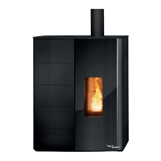
ECOFIRE TWIGGY
MANUALE DI INSTALLAZIONE E MANUTENZIONE
Il presente manuale è parte integrante del prodotto.
Si raccomanda di leggere attentamente le istruzioni prima
dell'installazione, manutenzione o utilizzo del prodotto.
Istruzioni originali
INSTALLATION AND MAINTENANCE MANUAL
This manual is an integral part of the product.
Read the instructions carefully before installing, servicing or
operating the product.
Translation of the original instructions
INSTALLATIONS UND WARTUNGSANLEITUNGEN
Die vorliegende Anleitung ist fester Bestandteil des Produkts.
Vor der Installation, Wartung und Verwendung die
Anleitugen stets aufmerksam durchlesen.
Übersetzung der Original-Bedienungsanleitung
NOTICE D'INSTALLATION ET D'ENTRETIEN
Le présent manuel fait partie intégrante du produit.
Il est conseillé de lire attentivement les consignes avant
l'installation, l'entretien ou l'utilisation du produit.
Traduction des instructions originales
MANUAL DE INSTALACIÓN Y MANTENIMIENTO
Este manual es parte integrante del producto.
Se recomienda leer detenidamente las instrucciones antes
de la instalación, el mantenimiento y el uso del producto.
Traducción de las instrucciones originales
Werbung
Kapitel
Inhaltsverzeichnis

Verwandte Anleitungen für Palazzetti TWIGGY


Inhaltszusammenfassung für Palazzetti TWIGGY
- Seite 1 ECOFIRE TWIGGY MANUALE DI INSTALLAZIONE E MANUTENZIONE Il presente manuale è parte integrante del prodotto. Si raccomanda di leggere attentamente le istruzioni prima dell’installazione, manutenzione o utilizzo del prodotto. Istruzioni originali INSTALLATION AND MAINTENANCE MANUAL This manual is an integral part of the product.
- Seite 2 We’d like to thank you for having purchased one of our products and congratulate you on your choice. To make sure you get the most out of TWIGGY, please carefully follow the instructions provided in this manual. Sehr geehrter Kunde, Zuallererst möchten wir Ihnen für den uns gewährten Vorzug...
-
Seite 3: Inhaltsverzeichnis
ITALIANO ENGLISH DEUTSCH FRANÇAIS ESPAÑOL INDICE 1 PREMESSA GENERALE Simbologia Destinazione d’uso Scopo e contenuto del manuale Conservazione del manuale Aggiornamento del manuale Generalità Conformità Responsabilità del costruttore Assistenza tecnica e manutenzione 1.10 Parti di ricambio 1.11 Targhetta matricola 1.12 Consegna dell’apparecchio 2 AVVERTENZE PER LA SICUREZZA Avvertenze per l’installatore 2.2 Avvertenze per il personale tecnico addetto alla manutenzione... - Seite 4 6 INSTALLAZIONE Considerazioni generali 6.2 Configurazioni installative 6.3 Circolazione dell’aria canalizzata 6.4 Livellamento dell’apparecchio 6.5 Collegamento elettrico 6.6 Ottimizzazione della combustione 7 CONFIGURAZIONE INIZIALE Configurazione 1 - Sonda ambiente 7.2 Configurazione 2 - Termostato ambiente 7.3 Primo avvio 8 MANUTENZIONE Manutenzione del sistema fumario 8.2 Manutenzione dell'apparecchio 8.3 Programma di pulizia e manutenzione...
-
Seite 5: Premessa Generale
Palazzetti. Il manuale d’installazione è parte integrante Palazzetti si riserva il diritto di modificare spe- dell’apparecchio. cifiche e caratteristiche tecniche e/o funzionali Deterioramento o smarrimento del prodotto in qualsiasi momento senza darne preavviso. -
Seite 6: Conformità
La responsabilità delle opere eseguite per l’in- Sono state applicate le seguenti norme armoniz- stallazione dell'apparecchio non può essere con- zate e/o regolamenti: siderata a carico della Palazzetti; essa è e rimane EMCD: a carico dell’installatore, al quale è demandata - EN 55014-1:2017 l’esecuzione delle verifiche relative alla canna... -
Seite 7: Assistenza Tecnica E Manutenzione
L’apparecchio viene consegnato perfettamente imballato e fissato ad una pedana in legno che Palazzetti mette a disposizione una fitta rete di ne permette la movimentazione mediante car- centri di assistenza con tecnici specializzati, for- relli elevatori e/o altri mezzi. -
Seite 8: Avvertenze Per La Sicurezza
AVVERTENZE PER LA Verificare che le predisposizioni SICUREZZA della canna fumaria e della presa d’aria siano conformi al tipo d’installazione. Avvertenze per l’installatore Osservare le prescrizioni indicate nel Non effettuare collegamenti elettrici presente manuale. volanti con cavi provvisori o non isolati. Verificare che la messa a terra dell’im- Le istruzioni di montaggio e pianto elettrico sia efficiente. -
Seite 9: Avvertenze Per Il Personale Tecnico Addetto Alla Manutenzione
ITALIANO ENGLISH DEUTSCH FRANÇAIS ESPAÑOL 2.2 Avvertenze per il personale Non toccare e non avvicinarsi tecnico addetto alla manutenzione al vetro della porta focolare, potrebbe causare ustioni; non Le operazioni di manutenzione devono guardare la fiamma per lungo essere eseguite solo da personale auto- tempo. - Seite 10 il distacco dell'alimentazione elettrica. In caso di incendio nella canna fu- maria, spegnere la stufa, scollegarla Rispettare le istruzioni e gli avvertimen- dall’alimentazione e non aprire lo ti evidenziati dalle targhette esposte sportello. Quindi chiamare le autorità sull'apparecchio. competenti. Le targhette sono dispositivi antinfortu- In caso di guasto al sistema di accen- nistici, pertanto devono essere sempre sione, non accendere la stufa con ma-...
- Seite 11 ITALIANO ENGLISH DEUTSCH FRANÇAIS ESPAÑOL L’accumulo di pellet incombusto nel combustibile avente le caratteristiche braciere dopo una mancata accensione riportate alla voce "Caratteristiche deve essere rimosso prima di procedere combustibile"; con un nuovo tentativo di accensione. • non utilizzare solventi, acidi, detersivi Se il braciere non viene pulito e sotto- o prodotti aggressivi per la pulizia posto a interventi di manutenzione si...
-
Seite 12: Caratteristiche Del Combustibile
CARATTERISTICHE DEL II pellet umido e/o freddo (5 °C) riduce la poten- zialità termica del combustibile ed obbliga ad COMBUSTIBILE effettuare maggiore manutenzione di pulizia del braciere (materiale incombusto) e del focolare. Caratteristiche del combustibile Porre particolare attenzione nello stoc- caggio e movimentazione dei sacchi di II pellet (Fig. -
Seite 13: Rimozione Dalla Paletta Di Trasporto
ITALIANO ENGLISH DEUTSCH FRANÇAIS ESPAÑOL 4.1 Rimozione dalla paletta di 4.3 Verifica piano d'appoggio trasporto Verificare la portata del solaio. Per rimuovere l'apparecchio dalla paletta di tra- Nel caso di un solaio non idoneo a sostenere il sporto rimuovere le viti come da Fig. 3. peso dell'apparecchio procedere all'installazione di opportune piastre in acciaio (A - Fig. -
Seite 14: Preparazione Del Luogo Di Installazione
PREPARAZIONE DEL pulizia. Il costruttore declina ogni responsabilità per LUOGO DI INSTALLAZIONE eventuali variazioni delle caratteristiche del mate- riale costituente il pavimento sotto la protezione. Considerazioni generali Prevedere uno spazio tecnico accessi- Nei paragrafi successivi sono riportate alcune bile per le eventuali manutenzioni. indicazioni da rispettare per ottenere il massimo rendimento del prodotto acquistato e il funzio- Si ricorda di rispettare la distanza minima dai... - Seite 15 ITALIANO ENGLISH DEUTSCH FRANÇAIS ESPAÑOL Prelievo dell'aria comburente dall'esterno Prelievo dell'aria comburente in ambiente Realizzare la presa d'aria sulla parete (Fig. 9 - PA In questo caso è possibile in alternativa: = Presa d'Aria), e lasciare che l'apparecchio sia • canalizzare l'aria comburente sfruttando un libero di prelevare aria in ambiente.
-
Seite 16: Raccordo Fumi
Se nel locale di installazione sono pre- senti e funzionanti uno o più ventilato- ri di estrazione (cappe di aspirazione) si potrebbero verificare malfunziona- menti alla combustione causati dalla scarsità di aria comburente. 5.5 Raccordo fumi L'apparecchio funziona con la camera di combu- stione in depressione è... - Seite 17 ITALIANO ENGLISH DEUTSCH FRANÇAIS ESPAÑOL Fig. 11a Fig. 11b Fig. 12 A) Comignolo antivento 1) Materiale non combustibile B) Sigillare 2) Tubazione in acciaio C) Ispezione 3) Pannello di chiusura A livello di ulteriore misura di sicurezza è previsto In caso di camino di sezione maggiore un raccordo filettato con tappo di chiusura "R", è...
-
Seite 18: Scarico Fumi Posteriore
5.7 Scarico fumi posteriore La stufa è predisposta per la conversione tubo uscita fumi da superiore a posteriore (Fig. 14 - Fig. 15). Rimuovere lo schienale (A), tappo ispezione posteriore (B), il tappo fumi (C) ed il collare fumi superiore (D) agendo sulle viti di ogni singolo componente. -
Seite 19: Installazione
ITALIANO ENGLISH DEUTSCH FRANÇAIS ESPAÑOL INSTALLAZIONE 6.2.1 Tubo coassiale È possibile sfruttare un tubo coassiale per l’e- Considerazioni generali spulsione dei fumi e la contemporanea ripresa dell’aria comburente. Nei paragrafi successivi sono riportate alcune Per far ciò: indicazioni da rispettare per ottenere il massimo rendimento dal prodotto acquistato. - Seite 20 6.2.2 Tubo monoparete e ripresa aria in ambiente In questo caso l’aria comburente verrà presa dall’ambiente (Fig. 18). Per far ciò: • Rimuovere il tubo coassiale. • Unire il collare estetico (A) all’anello di supporto (B) mediante l’utilizzo dei 6 dadi in dotazione e allineare l’assieme al top regolando i dadi.
-
Seite 21: Circolazione Dell'aria Canalizzata
ITALIANO ENGLISH DEUTSCH FRANÇAIS ESPAÑOL 6.3 Circolazione dell’aria canalizzata Quando la stufa viene utilizzata per riscaldare 2 o più locali adiacenti è indispensabile favorire La stufa è predisposta per il collegamento aria il ricircolo dell’aria ambiente per uniformare la calda posteriore canalizzabile. temperatura nelle varie stanze. -
Seite 22: Livellamento Dell'apparecchio
6.3.1 Selettore uscita aria calda 6.4 Livellamento dell’apparecchio Agendo sulla chiave a brugola è possibile sceglie- L'apparecchio deve essere livellato, con l'ausilio di re l'uscita dell'aria calda: un'asta a bolla, agendo sui piedini di regolazione (Fig. 28). • superiore (Fig. 26) ; A = Asta a bolla. -
Seite 23: Ottimizzazione Della Combustione
ITALIANO ENGLISH DEUTSCH FRANÇAIS ESPAÑOL CONFIGURAZIONE Il condotto di scarico fumi deve essere dotato di un proprio collegamento a INIZIALE terra. In funzione della tipologia di installazione è ne- 6.6 Ottimizzazione della combustione cessario impostare la configurazione ideale per il corretto funzionamento. -
Seite 24: Configurazione 1 - Sonda Ambiente
Configurazione 1 - Sonda ambiente Sonda temperatura ambiente Fig. 30 L'apparecchio modula la potenza in funzione La configurazione 1 è la configurazione della temperatura ambiente letta dalla sonda di default per questo apparecchio. In ambiente posta a bordo della stufa stessa. questo caso non è... -
Seite 25: Configurazione 2 - Termostato Ambiente
ITALIANO ENGLISH DEUTSCH FRANÇAIS ESPAÑOL 7.2 Configurazione 2 - Termostato ambiente 22.15 20.3 °C Termostato esterno Sonda temperatura ambiente Fig. 31 Nella configurazione 2 l'apparecchio viene co- In questa configurazione l'apparecchio mandato da un termostato (o cronotermostato) si spegne quando il termostato esterno esterno (non in dotazione) che accende e spegne è... -
Seite 26: Primo Avvio
7.3 Primo avvio Collegare l'apparecchio alla rete elettrica, agire sull’interruttore di accensione posto sul retro dell'apparecchio posizionandolo su “I”. Fig. 32 Se il collegamento è corretto l'apparecchio emette una serie di segnali acustici intermittenti e si accende il display. Assicurarsi di non toccare il pannello di comando nel momento in cui viene data alimentazione all'apparecchio. -
Seite 27: Manutenzione
ITALIANO ENGLISH DEUTSCH FRANÇAIS ESPAÑOL MANUTENZIONE 8.2 Manutenzione dell'apparecchio Da effettuarsi almeno una vola all’anno, oppure Le operazioni di manutenzione devono essere ogni qual volta l'apparecchio segnala la richiesta effettuate da parte di un centro di assistenza di manutenzione. tecnico autorizzato. Durante l’operazione di manutenzione, il tecnico Prima di effettuare qualsiasi operazione di ma- dovrà:... -
Seite 28: Programma Di Pulizia E Manutenzione
8.3 Programma di pulizia e manutenzione 8.3.1 Utente OGNI OGNI 1 MESE 1 ANNO (*) ACCENSIONE SETTIMANA Braciere Cassetto/Vano cenere Vetro Caldaia Collettore fumi 8.3.2 Centro di assistenza tecnico abilitato 1 ANNO (*) Guarnizioni porta e braciere Condotto di evacuazione fumi Ventilatori (*) Almeno una volta all‘anno oppure ogni 40 quintali di pellet bruciati. -
Seite 29: Pulizia Condotto Di Evacuazione Fumi
(Fig. 33 - Fig. 34 - Fig. 35). La manutenzione non pone particolari problemi e va eseguita conformemente alle prescri- zioni della Scheda Tecnica. Per il modello TWIGGY, per garantirne durabilità, manutenzione e pulitura, è necessario tenere conto della struttura del circuito di scarico dei prodotti di combustione nella stufa e della presenza di un vano per la raccolta della fuliggine all’inter-... -
Seite 30: Demolizione E Smaltimento
DEMOLIZIONE E SMALTIMENTO La demolizione e lo smaltimento dell'apparecchio sono ad esclusivo carico e responsabilità del pro- prietario che dovrà agire in osservanza delle leggi vigenti nel proprio Paese in materia di sicurezza, rispetto e tutela dell’ambiente. Smantellamento e smaltimento possono essere affidati anche a terzi, purché si ricorra sempre a ditte autorizzate al recupero ed all’eliminazione dei materiali in questione. - Seite 32 CONTENTS 1 GENERAL INTRODUCTION Symbols Intended use Purpose and content of the manual Preservation of the manual Update of this manual Overview Conformity Responsibility of the manufacturer Technical assistance and maintenance 1.10 Spare Parts 1.11 Serial identification plate 1.12 Delivery of the appliance 2 SAFETY WARNING Warnings for the installer 2.2 Warnings for technical maintenance personnel...
- Seite 33 ITALIANO ENGLISH DEUTSCH FRANÇAIS ESPAÑOL 6 INSTALLATION General considerations 6.2 Installation configurations 6.3 Circulation of ducted air 6.4 Levelling of the appliance 6.5 Electrical connection 6.6 Fuel optimisation 7 INITIAL CONFIGURATION Configuration 1 - Room probe 7.2 Configuration 2 - Room thermostat 7.3 First start up 8 MAINTENANCE Maintenance of the smoke system...
-
Seite 34: General Introduction
Pala- zzetti specialized personnel. The installation manual is an integral part of the appliance. Palazzetti reserves the right to change specifi- cations and technical and/or functional charac- Deterioration or loss teristics of the product at any time without prior If necessary, request a further copy from notice. -
Seite 35: Conformity
Responsibility for the works carried out for the in- The following harmonised standards and/or reg- stallation of the appliance cannot be considered ulations have been applied: to be taken on by Palazzetti; it is and remains the EMCD: responsibility of the installer, who is responsible - EN 55014-1:2017... -
Seite 36: Technical Assistance And Maintenance
1.12 Delivery of the appliance maintenance The appliance is delivered perfectly packaged and fixed to a wooden platform which allows Palazzetti has a dense network of service centres handling it using fork lift trucks and/or other with specialized, trained and skilled technicians. means. -
Seite 37: Safety Warning
ITALIANO ENGLISH DEUTSCH FRANÇAIS ESPAÑOL SAFETY WARNING Check that the chimney flue and air inlet set-ups conform to Warnings for the installer the type of installation. Observe the prescriptions contained in Do not carry out on-the-fly electrical this manual. connections with temporary or uninsu- lated cables. -
Seite 38: Warnings For Technical Maintenance Personnel
2.2 Warnings for technical Do not touch and do not get maintenance personnel close to the glass of the firebox door, it could cause burns, do Maintenance operations must only be not look at the flame for a long carried out by authorised and qualified time. - Seite 39 ITALIANO ENGLISH DEUTSCH FRANÇAIS ESPAÑOL Respect the instructions and warnings In the event of smoke escaping into highlighted on the sign plates dis- the room or explosion damaging the played on the appliance. device, turn it off, ventilate the room and immediately contact the installer/ The sign plates are accident prevention service technician.
- Seite 40 It is forbidden to introduce fuels other It is forbidden to manually load than wood pellets into the tank. the pellets into the brazier, as this incorrect behaviour could Some tips avoid corrosion generate an abnormal quantity phenomena: of unburnt gases, with the con- •...
-
Seite 41: Fuel Characteristics
ITALIANO ENGLISH DEUTSCH FRANÇAIS ESPAÑOL FUEL CHARACTERISTICS Wet and/or cold pellets (5 °C) reduce the thermal potential of the fuel resulting in the need for more cleaning maintenance of the brazier (unburned Fuel characteristics material) and of the firebox. The pellets (Fig. 2) are a compound consisting of Pay particular attention to the stor- various types of wood pressed with mechanical age and handling of pellet bags. -
Seite 42: Removal From The Transport Pallet
4.1 Removal from the transport pallet In the case of a floor that is not suitable to sup- port the weight of the appliance, install suitable To remove the appliance from the transport steel plates (A - Fig. 4) or concrete base (A - Fig. pallet, remove the screws as shown in Fig. -
Seite 43: Preparing The Place Of Installation
ITALIANO ENGLISH DEUTSCH FRANÇAIS ESPAÑOL PREPARING THE PLACE front during cleaning from any falling burning residues. OF INSTALLATION The manufacturer declines all responsibility for any variations in the characteristics of the mate- General considerations rial constituting the floor under the protection. In the following paragraphs there are some Set up an accessible technical space indications to be respected in order to obtain... - Seite 44 Extraction of combustion air from outside Extraction of combustion air in the room Create the air intake on the wall (Fig. 9 - PA = Air In this case it is possible as an alternative: Intake), and leave the appliance free to bring air •...
-
Seite 45: Flue Gas Fitting
ITALIANO ENGLISH DEUTSCH FRANÇAIS ESPAÑOL If one or more extraction fans (extrac- tor hoods) are present and operating in the installation room, combustion malfunctions may occur due to lack of combustion air. 5.5 Flue gas fitting The appliance works with the combustion cham- ber at negative pressure. - Seite 46 Fig. 11a Fig. 11b Fig. 12 A) Wind-proof cowl 2) Steel piping B) Seal 3) Closing panel C) Inspect As a further safety measure, a threaded connec- tion with closing cap "R" is provided, in order to If the chimney has a larger section, it connect a condensate drain pipe in the unlikely event that it should be necessary (Fig.
-
Seite 47: Rear Smoke Outlet
ITALIANO ENGLISH DEUTSCH FRANÇAIS ESPAÑOL 5.7 Rear smoke outlet The stove is designed to convert the smoke outlet pipe from top to rear (Fig. Fig. 15). Remove the back plate (A), rear inspection cap (B), the smoke cap (C) and the upper smoke collar (D) by loosening the screws of each indi- vidual component. -
Seite 48: Installation
INSTALLATION 6.2.1 Coaxial pipe It is possible to use a coaxial pipe for the expul- General considerations sion of fumes and for simultaneous recovery of the combustion air. In the following paragraphs some indications To achieve this: are provided to be respected in order to obtain the maximum performance from the purchased •... - Seite 49 ITALIANO ENGLISH DEUTSCH FRANÇAIS ESPAÑOL 6.2.2 Single wall pipe and room air intake In this case the combustion air will be drawn from the environment (Fig. 18). To achieve this: • Remove the coaxial pipe. • Join the aesthetic collar (A) to the support ring (B) using the 6 nuts supplied and align the as- sembly with the top by adjusting the nuts.
-
Seite 50: Circulation Of Ducted Air
6.3 Circulation of ducted air When the stove is used to heat 2 or more adjacent rooms, it is essential to encourage recirculation The stove is designed for ductable rear hot air of the ambient air to uniform the temperature in connection. -
Seite 51: Levelling Of The Appliance
ITALIANO ENGLISH DEUTSCH FRANÇAIS ESPAÑOL 6.3.1 Hot air outlet selector 6.4 Levelling of the appliance Using the Allen key it is possible to choose the The appliance must be levelled, with the aid of a hot air outlet: spirit level, by acting on the adjustment feet (Fig. 28). -
Seite 52: Fuel Optimisation
INITIAL CONFIGURATION The flue gas evacuation duct must be equipped with its own earth Depending on the type of installation it is neces- connection. sary to set up the ideal configuration for correct operation. 6.6 Fuel optimisation Excellent fuel depends on different factors (type Two different configurations are possible: of installation, operating and maintenance con- ditions, type of pellets, etc.) -
Seite 53: Configuration 1 - Room Probe
ITALIANO ENGLISH DEUTSCH FRANÇAIS ESPAÑOL Configuration 1 - Room probe Sonda temperatura ambiente Fig. 30 The appliance modulates the power according to Configuration 1 is the default configu- the room temperature read by the room probe ration for this appliance. In this case it placed on the stove itself. -
Seite 54: Configuration 2 - Room Thermostat
7.2 Configuration 2 - Room thermostat 22.15 20.3 °C Termostato esterno Sonda temperatura ambiente Fig. 31 In configuration 2 the appliance is controlled by In this configuration the appliance an external thermostat (or chronothermostat) turns off when the external thermo- (not supplied) which turns the appliance on and stat is satisfied, or it will modulate the off according to the temperature set (Fig. -
Seite 55: First Start Up
ITALIANO ENGLISH DEUTSCH FRANÇAIS ESPAÑOL 7.3 First start up Connect the appliance to the mains, operate the power switch on the back of the appliance by turning it to "I". Fig. 32 If the connection is correct, the appliance emits a series of intermittent noises and the display lights up. -
Seite 56: Maintenance
MAINTENANCE 8.2 Appliance maintenance To be carried out at least once a year, or every Maintenance operations must be performed by time the appliance signals maintenance request. an authorised technical assistance centre. During the maintenance operation, the techni- Before performing any maintenance operation, cian must: take the following precautions: •... -
Seite 57: Cleaning And Maintenance Program
ITALIANO ENGLISH DEUTSCH FRANÇAIS ESPAÑOL 8.3 Cleaning and maintenance program 8.3.1 User EVERY TIME THE AP- EVERY WEEK 1 MONTH 1 YEAR (*) PLIANCE IS TURNED ON Brazier Ash drawer/compartment Glass Boiler Fume manifold 8.3.2 Enabled technical assistance centre 1 YEAR (*) Door and burn pot seals Smoke exhaust duct Fans... -
Seite 58: Smoke Exhaust Duct Cleaning
8.4 Smoke exhaust duct cleaning At least once a season it is necessary to remove the front cap of the stove and to remove the ash col- lection cap and clean the smoke collector with an ash vacuum cleaner and a brush. To achieve this it is necessary to open the door and access the compartment by removing the two inspection caps as shown in the figure (Fig. -
Seite 59: Demolition And Disposal
ITALIANO ENGLISH DEUTSCH FRANÇAIS ESPAÑOL DEMOLITION AND DISPOSAL The demolition and disposal of the appliance are the sole liability and responsibility of the owner who must act in compliance with the laws in force in their country regarding safety, respect and protection of the environment. - Seite 61 ITALIANO ENGLISH DEUTSCH FRANÇAIS ESPAÑOL INDICE 1 ALLGEMEINES Symbole Verwendungszweck Zweck und Inhalt des Handbuchs Aufbewahrung des Handbuchs Aktualisierung des Handbuchs Allgemeines Konformität Herstellerhaftung Technischer Kundendienst und Wartung 1.10 Ersatzteile 1.11 Typenschild 1.12 Lieferung des Geräts 2 SICHERHEITSHINWEISE Warnhinweise für den Installateur 2.2 Hinweise für das Wartungspersonal 2.3 Warnungen für den Benutzer 3 EIGENSCHAFTEN DES BRENNSTOFFS...
- Seite 62 6 INSTALLATION Allgemeine Anmerkungen 6.2 Installations-Konfigurationen 6.3 Kanalisierte Luftzirkulation 6.4 Nivellierung des Geräts 6.5 Elektrischer Anschluss 6.6 Verbrennungsoptimierung 7 ANFÄNGLICHE KONFIGURATION Konfiguration 1 - Raumsonde 7.2 Konfiguration 2 - Raumthermostat 7.3 Erste Inbetriebnahme 8 WARTUNG Wartung des Rauchabzugsystems 8.2 Wartung des Geräts 8.3 Reinigungs- und Wartungsprogramm 8.4 Reinigung des Rauchabzugskanals 9 VERSCHROTTUNG UND ENTSORGUNG...
-
Seite 63: Allgemeines
ESPAÑOL ALLGEMEINES Zweck und Inhalt des Handbuchs Der Zweck dieses Handbuchs besteht darin, die Die Heizgeräte von Palazzetti sind gemäß den Grund- und Grundregeln für eine korrekte Instal- von den europäischen Richtlinien angegebenen lation des Geräts zu vermitteln. Sicherheitsvorschriften hergestellt und geprüft. -
Seite 64: Konformität
Die Verantwortung für die für die Installation des - EN 61000-3-3:2014 /EC:2016 Geräts ausgeführten Arbeiten liegt nicht beim - EN 55014-2:2015 Unternehmen PALAZZETTI; sie liegt und bleibt beim Installateur, der mit der Durchführung EMF: der Prüfungen bezüglich des Rauchabzugs, des... -
Seite 65: Technischer Kundendienst Und Wartung
1.12 Lieferung des Geräts Wartung Das Gerät wird perfekt verpackt und auf einer Holzpalette befestigt, die sein Handling durch Palazzetti verfügt über ein dichtes Kunden- Gabelstapler und/oder andere Mittel erlaubt, dienstnetzwerk mit Zentren mit spezialisierten, geliefert. ausgebildeten und geschulten Technikern. -
Seite 66: Sicherheitshinweise
SICHERHEITSHINWEISE Sicherstellen, dass sich Rauchabzug und die Lüftungs- Warnhinweise für den Installateur öffnung für die vorgesehene Installation eignen. Die im vorliegenden Handbuch ent- haltenen Vorgaben müssen beachtet Keine elektrischen Anschlüsse mit pro- werden. visorischen oder nicht isolierten Kabeln ausführen. Die Montage- und Demon- tagearbeiten dürfen nur von Überprüfen Sie, ob die Erdung der spezialisierten Fachtechnikern... -
Seite 67: Hinweise Für Das Wartungspersonal
ITALIANO ENGLISH DEUTSCH FRANÇAIS ESPAÑOL 2.2 Hinweise für das Berühren Sie nicht die Glasscheibe Wartungspersonal der Feuerraumtür und nähern Sie sich ihr nicht, da dies zu Verbren- Wartungsarbeiten dürfen nur von au- nungen führen kann. Nicht für län- torisiertem und qualifiziertem Personal gere Zeit in die Flamme schauen. - Seite 68 denen Innenbereichen autorisiert Falls Rauch in den Raum entweicht oder werden, auch nicht bei abgetrennter eine Explosion das Gerät beschädigt, Stromversorgung. schalten Sie es aus, belüften Sie den Raum und wenden Sie sich umgehend Beachten Sie die Anweisungen und an den Installateur/Servicetechniker. Warnhinweise auf den Typenschildern am Gerät.
- Seite 69 ITALIANO ENGLISH DEUTSCH FRANÇAIS ESPAÑOL Flüssigkeiten während des Betriebs in Es ist verboten, Pellets von einem sicheren Abstand zum Gerät. Hand in den Brenner zu laden, da dieses falsche Verhalten eine Es ist verboten, andere Brennstoffe als anormale Menge unverbrann- Holzpellets in den Fülltrichter zu füllen.
-
Seite 70: Eigenschaften Des Brennstoffs
EIGENSCHAFTEN DES diese die richtige Temperatur und Luftfeuchtig- keit haben und in einem sicheren Abstand (min- BRENNSTOFFS destens einen Meter) von Wärmequellen stehen. Feuchte und/oder kalte Pellets (5 °C) haben eine Eigenschaften des Brennstoffs geringere Heizleistung und bewirken, dass die Brennschale (unverbranntes Material) und der Das Pellet (Abb. -
Seite 71: Entfernen Der Transportpalette
ITALIANO ENGLISH DEUTSCH FRANÇAIS ESPAÑOL 4.1 Entfernen der Transportpalette 4.3 Prüfen der Auflagefläche Um das Gerät von der Transportpalette zu ent- Kontrollieren Sie die Tragfähigkeit der Decke. fernen, entfernen Sie die Schrauben wie in Abb. Im Falle eines Bodens, der nicht geeignet ist, 3 dargestellt zu überprüfen. -
Seite 72: Vorbereitung Des Installationsortes
VORBEREITUNG DES brennungsresten schützen, geschützt werden. Der Hersteller lehnt jegliche Haftung für even- INSTALLATIONSORTES tuelle Änderungen der Eigenschaften des Ma- terials, aus dem der Boden unter dem Schutz Allgemeine Anmerkungen besteht, ab. In den folgenden Abschnitten werden einige Einen technischen Raum vorsehen,der Hinweise gegeben, die für eine maximale Leis- für eventuelle Wartungsarbeiten zu- tung des Produkts und einen sicheren Betrieb... - Seite 73 ITALIANO ENGLISH DEUTSCH FRANÇAIS ESPAÑOL Absaugung der Verbrennungsluft von außen Absaugung der Verbrennungsluft im Raum In diesem Fall ist es alternativ möglich: Den Lufteinlass an der Wand vornehmen (Abb. 9 - PA = Lufteinlass ), und das Gerät Luft in den •...
-
Seite 74: Rauchanschluss
Wenn ein oder mehrere Absaugven- tilatoren (Absaughauben) vorhanden sind und im Aufstellungsraum arbei- ten, kann es aufgrund fehlender Ver- brennungsluft zu Verbrennungsstö- rungen kommen. 5.5 Rauchanschluss Das Gerät funktioniert mit Feuerraum in Unter- druck - unbedingt sicherstellen, dass der Rauch- abzug hermetisch verschlossen ist (Aufgabe die dem Installateur obliegt). - Seite 75 ITALIANO ENGLISH DEUTSCH FRANÇAIS ESPAÑOL Abb. 11a Abb. 11b Abb. 12 A) Winddichter Schornstein 1) Nicht brennbares Material B) Abdichten 2) Stahlrohrleitung C) Inspektion 3) Schlusspanel Als zusätzliche Sicherheitsmaßnahme ist ein Wenn der Schornstein einen größeren Gewindeanschluss Verschlussdeckel "R" Querschnitt hat, muss er mit einem vorgesehen, um im unwahrscheinlichen Fall des angemessen isolierten Stahlrohr „ver- Falles eine Kondensatabflussleitung anschließen...
-
Seite 76: Hinterer Rauchabzug
5.7 Hinterer Rauchabzug Der Ofen ist so konstruiert, dass das Rauchabzugsrohr von oben nach hinten umgebaut werden kann (Abb. 14 - Abb. 15). Entfernen Sie die Rückwand (A), die hintere Inspektionskappe (B), die Rauchkappe (C) und den oberen Rauchstellring (D), indem Sie auf die Schrauben der einzelnen Komponenten Abb. -
Seite 77: Installation
ITALIANO ENGLISH DEUTSCH FRANÇAIS ESPAÑOL INSTALLATION 6.2.1 Koaxiales Rohr Es ist möglich, ein koaxiales Rohr für die Ableitung Allgemeine Anmerkungen der Rauchgase und die gleichzeitige Ansaugung der Verbrennungsluft zu verwenden. In den folgenden Absätzen werden einige zu Um dies zu tun: befolgende Anweisungen aufgeführt, um den maximalen Wirkungsgrad des erworbenen Pro- •... -
Seite 78: Einwandiges Rohr Und Lufteinlass Im Raum
6.2.2 Einwandiges Rohr und Lufteinlass im Raum In diesem Fall wird die Verbrennungsluft aus dem Raum entnommen (Abb. 18). Um dies zu tun: • Entfernen Sie das koaxiale Rohr. • Verbinden Sie den ästhetischen Stellring (A) mit dem Stützring (B) mit den 6 mitgelieferten Muttern und richten Sie die Baugruppe mit der Oberseite aus, indem Sie die Muttern einstellen. -
Seite 79: Kanalisierte Luftzirkulation
ITALIANO ENGLISH DEUTSCH FRANÇAIS ESPAÑOL 6.3 Kanalisierte Luftzirkulation Wenn der Ofen zum Beheizen von 2 oder mehr benachbarten Räumen verwendet wird, ist Der Ofen ist für einen kanalisierbaren hinteren es wichtig, die Umluftumwälzung der Umge- Warmluftanschluss ausgelegt. bungsluft zu fördern, um die Temperatur in den verschiedenen Räumen zu vereinheitlichen. -
Seite 80: Wahlschalter Für Warmluftauslass
6.3.1 Wahlschalter für Warmluftauslass 6.4 Nivellierung des Geräts Der Warmluftauslass kann mit dem Inbusschlüs- Das Gerät muss mit Hilfe eines Blasenstabes mit sel gewählt werden: Hilfe der Stellfüsse nivelliert werden (Abb. 28). • oben (Abb. 26); A = Wasserwaage. • oben und hinten (Abb. 27). Abb. -
Seite 81: Verbrennungsoptimierung
ITALIANO ENGLISH DEUTSCH FRANÇAIS ESPAÑOL ANFÄNGLICHE Der Rauchableitkanal muss einen ei- genen Erdungsanschluss haben. KONFIGURATION 6.6 Verbrennungsoptimierung Abhängig von der Art der Installation ist es notwendig, die ideale Konfiguration für einen Die optimale Verbrennung hängt von verschie- korrekten Betrieb einzustellen. denen Faktoren ab (Art der Anlage, Betriebs- und Wartungsbedingungen, Art der Pellets, usw.) Sie können zwischen zwei verschiedenen Konfi-... -
Seite 82: Konfiguration 1 - Raumsonde
Konfiguration 1 - Raumsonde Sonda temperatura ambiente Abb. 30 Das Gerät moduliert die Leistung in Abhän- Konfiguration 1 ist die Standardkon- gigkeit von der Raumtemperatur, die von der figuration für dieses Gerät. In diesem Raumsonde an Bord des Ofens selbst abgelesen Fall ist es nicht notwendig, irgendwel- wird. -
Seite 83: Konfiguration 2 - Raumthermostat
ITALIANO ENGLISH DEUTSCH FRANÇAIS ESPAÑOL 7.2 Konfiguration 2 - Raumthermostat 22.15 20.3 °C Termostato esterno Sonda temperatura ambiente Abb. 31 In der Konfiguration 2 wird das Gerät durch ein In dieser Konfiguration schaltet sich externes Thermostat (oder Thermostat-Zeit- das Gerät aus, wenn der externe Ther- schaltuhr) (nicht mitgeliefert) gesteuert, welches mostat zufrieden ist, oder er moduliert das Gerät je nach eingestellter Temperatur ein-... -
Seite 84: Erste Inbetriebnahme
7.3 Erste Inbetriebnahme Schließen Sie das Gerät an die Stromversorgung an, stellen Sie den Zündschalter auf der Rücksei- te des Geräts auf "I". Abb. 32 Wenn der Anschluss korrekt ist, gibt das Gerät eine Reihe von intermittierenden Signaltönen ab und die Anzeige leuchtet auf. Achten Sie darauf, das Bedienfeld nicht zu berühren, wenn das Gerät mit Strom versorgt wird. -
Seite 85: Wartung
ITALIANO ENGLISH DEUTSCH FRANÇAIS ESPAÑOL WARTUNG 8.2 Wartung des Geräts Mindestens einmal im Jahr oder jedes Mal, wenn Die Wartungsarbeiten müssen von einem auto- das Gerät die Anfrage nach Wartung anzeigt. risierten technischen Kundendienst ausgeführt Bei den Wartungsarbeiten muss der Techniker werden. -
Seite 86: Reinigungs- Und Wartungsprogramm
8.3 Reinigungs- und Wartungsprogramm 8.3.1 Benutzer BEI JEDER JEDE WOCHE 1 MONAT 1 JAHR (*) ZÜNDUNG Brennschale Aschenlade/-Fach Glas Kessel Rauchsammler 8.3.2 Lizenziertes Kundentienstzentrum 1 JAHR (*) Tür- und Kohlenbeckendichtungen Rauchabzugskanal Ventilatoren (a) Mindestens einmal pro Jahr oder alle 4000 kg verbranntes Brennmaterial. 004771070 - 17/11/2020... -
Seite 87: Reinigung Des Rauchabzugskanals
ITALIANO ENGLISH DEUTSCH FRANÇAIS ESPAÑOL 8.4 Reinigung des Rauchabzugskanals Mindestens einmal pro Saison ist es notwendig, die Frontkappe des Ofens zu entfernen und den Ascheauffangdeckel abzunehmen und den Rauchsammler mit einem Aschenbecher und einer Bürs- te zu reinigen. Dazu ist es notwendig, die Tür zu öffnen, Zugang zum Fach zu erhalten, indem die beiden Inspektionskappen wie in der Abbildung gezeigt entfernt werden (Abb. -
Seite 88: Verschrottung Und Entsorgung
VERSCHROTTUNG UND ENTSORGUNG Die Verschrottung und Entsorgung des Geräts liegen in der alleinigen Verantwortung des Eigentü- mers, der in Übereinstimmung mit den in seinem Land geltenden Gesetzen bezüglich Sicherheit, Respekt und Schutz der Umwelt handeln muss. Die Demontage und die Entsorgung können auch Dritten anvertraut werden, unter der Vorausset- zung, dass immer Firmen beauftragt werden, die für die Wiederverwertung und die Beseitigung der betreffenden Materialien autorisiert sind. - Seite 90 INDEX 1 INTRODUCTION Symboles utilisés Destination d’emploi Objet et contenu du manuel Conservation du manuel Mise à jour du manuel Généralités Conformité Responsabilité du fabricant Assistance technique et entretien 1.10 Pièces détachées 1.11 Plaque signalétique 1.12 Livraison de l’appareil 2 AVERTISSEMENTS POUR LA SÉCURITÉ Avertissements pour l'installateur 2.2 Avertissements pour les techniciens préposés à...
- Seite 91 ITALIANO ENGLISH DEUTSCH FRANÇAIS ESPAÑOL 6 INSTALLATION Considérations générales 6.2 Configurations d’installation 6.3 Circulation de l’air canalisé 6.4 Mise à niveau de l’appareil 6.5 Branchement électrique 6.6 Optimisation de la combustion 7 CONFIGURATION INITIALE Configuration 1 - Sonde ambiante 7.2 Configuration 2 - Thermostat ambiant 7.3 Premier démarrage 8 MAINTENANCE Maintenance du système d’évacuation de la fumée...
-
Seite 92: Introduction
Le manuel d’installation fait partie intégrante de spécialisé Palazzetti. l’appareil. Palazzetti se réserve le droit de modifier les spé- Perte ou détérioration cifications et les caractéristiques techniques et/ ou fonctionnelles du produit à tout moment sans Si nécessaire, demander un autre exemplaire à... -
Seite 93: Conformité
été appliqués : tallation de l’appareil ne peut pas être considérée EMCD : à la charge de la société Palazzetti ; en effet, celle- - EN 55014-1:2017 ci est et reste à la charge de l’installateur qui est - EN 61000-3-2:2015 tenu d’effectuer les contrôles relatifs au conduit... -
Seite 94: Assistance Technique Et Entretien
Assistance technique et entretien 1.12 Livraison de l’appareil Palazzetti met à disposition un réseau dense de L'appareil est livré parfaitement emballé et fixé centres d’assistance avec des techniciens spécia- à une palette en fois permettant de le déplacer lisés, formés et préparés. -
Seite 95: Avertissements Pour La Sécurité
ITALIANO ENGLISH DEUTSCH FRANÇAIS ESPAÑOL AVERTISSEMENTS POUR Vérifier que les prédispositions LA SÉCURITÉ du conduit de fumée et de l'ar- rivée d'air soient conformes au type d'installation. Avertissements pour l'installateur Respecter les consignes indiquées Ne pas effectuer de branchements dans le présent manuel. électriques volants avec des câbles provisoires ou non isolés. -
Seite 96: Avertissements Pour Les Techniciens Préposés À La Maintenance
2.2 Avertissements pour les Ne pas toucher et ne pas s’appro- techniciens préposés à la cher de la vitre du foyer, risque maintenance de brûlures ; ne pas regarder la flamme de façon trop prolongée. Les opérations de maintenance doivent être effectuées exclusivement par un Ne pas poser de linge directe- personnel autorisé... - Seite 97 ITALIANO ENGLISH DEUTSCH FRANÇAIS ESPAÑOL Respecter les instructions et les aver- reil, éteindre celui-ci, ventiler la pièce tissements contenus sur les plaques et contacter immédiatement l'installa- appliquées sur l’appareil. teur/technicien de service. Ces plaques sont des dispositifs de En cas d'incendie dans le conduit de la prévention des accidents ;...
- Seite 98 Il est interdit de verser dans le réservoir Il est interdit de charger ma- des combustibles autres que les gra- nuellement les granulés de bois nulés de bois (pellet). dans le brasero, car ce com- portement incorrect pourrait Conseils pour éviter les phénomènes générer une quantité...
-
Seite 99: Caractéristiques Du Combustible
ITALIANO ENGLISH DEUTSCH FRANÇAIS ESPAÑOL CARACTÉRISTIQUES DU sécurité (au moins 1 mètre) de toute source de chaleur. COMBUSTIBLE Les granulés humides et/ou froids (5 °C) réduisent la puissance thermique du combustible et oblige Caractéristiques du combustible à effectuer plus fréquemment l’entretien du bra- sier (matériau non brûlé) et du foyer. -
Seite 100: Enlèvement De La Palette De Transport
4.1 Enlèvement de la palette de 4.3 Contrôle du plan d’appui transport Vérifier la capacité de charge du plancher. Pour retirer l'appareil de la palette de transport, Dans le cas d'un sol non approprié pour suppor- retirer les vis comme indiqué en Fig. 3. ter le poids de l'appareil, procéder à... -
Seite 101: Préparation Du Lieu D'installation
ITALIANO ENGLISH DEUTSCH FRANÇAIS ESPAÑOL PRÉPARATION DU LIEU Le fabricant décline toute responsabilité en cas d’éventuelles variations caractéristiques D’INSTALLATION du matériau composant le plancher, sous la protection. Considérations générales Prévoir un espace technique accessible pour d'éventuelles interventions de Les paragraphes suivants contiennent quelques maintenance. - Seite 102 Prélèvement de l’air de combustion à l’extérieur Prélèvement de l’air de combustion dans l’environnement Dans ce cas, il est possible en alternative de : Réaliser la prise d’air sur la paroi (Fig. 9 - PA = Prise d’Air), et • canaliser l'air de combustion en utilisant un laisser l’appareil libre de prélever l’air dans la pièce.
-
Seite 103: Raccord Fumée
ITALIANO ENGLISH DEUTSCH FRANÇAIS ESPAÑOL Si un ou plusieurs ventilateurs d'extrac- tion (hottes d'aspiration) sont présents et fonctionnent dans le local d'installa- tion, des dysfonctionnements de com- bustion peuvent se produire en raison d'un manque d'air de combustion. 5.5 Raccord fumée L’appareil fonctionne avec la chambre de com- bustion sous vide ;... - Seite 104 Fig. 11a Fig. 11b Fig. 12 A) Chapeau anti-vent 1) Matériau non combustible B) Sceller 2) Tuyaux en acier C) Inspection 3) Panneau de fermeture Comme mesure de sécurité supplémentaire, un Si la section de la cheminée est supé- raccord fileté avec bouchon de fermeture « R » rieure, il est nécessaire d’« intuber »...
-
Seite 105: Évacuation Fumée Arrière
ITALIANO ENGLISH DEUTSCH FRANÇAIS ESPAÑOL 5.7 Évacuation fumée arrière Le poêle est conçu pour convertir le tube d’éva- cuation de la fumée du haut vers l’arrière (Fig. 14 - Fig. 15). Retirer le panneau arrière (A), le bouchon d'ins- pection arrière (B), le bouchon de la fumée (C) et le collier fumée supérieur (D) en agissant sur les vis de chaque composant. -
Seite 106: Installation
INSTALLATION 6.2.1 Tube coaxial Il est possible d'utiliser un tube coaxial pour Considérations générales l'expulsion de la fumée et l'admission simultanée d'air de combustion. Les paragraphes suivants fournissent des indi- Pour cela : cations à respecter pour obtenir le rendement maximal du produit acheté. •... - Seite 107 ITALIANO ENGLISH DEUTSCH FRANÇAIS ESPAÑOL 6.2.2 Tube à simple paroi et prise d'air dans la pièce Dans ce cas, l'air de combustion sera prélevé dans la pièce (Fig. 18). Pour cela : • Retirer le tube coaxial. • Relier le collier esthétique (A) à la bague de sup- port (B) à...
-
Seite 108: Circulation De L'air Canalisé
6.3 Circulation de l’air canalisé Quand le poêle est utilisé pour chauffer 2 ou plu- sieurs locaux adjacents, il est indispensable de favo- Le poêle est prédisposé pour la connexion d’air riser le recyclage de l’air ambiant pour uniformiser la chaud arrière canalisable. -
Seite 109: Mise À Niveau De L'appareil
ITALIANO ENGLISH DEUTSCH FRANÇAIS ESPAÑOL 6.3.1 Sélecteur sortie air chaud 6.4 Mise à niveau de l’appareil En agissant sur la clé Allen, il est possible de choi- L’appareil doit être mis à niveau, à l’aide d’un sir la sortie de l’air chaud : niveau à... -
Seite 110: Optimisation De La Combustion
CONFIGURATION Le conduit d'évacuation de la fumée doit être doté de sa propre mise à la INITIALE terre. En fonction du type d’installation, il est nécessaire 6.6 Optimisation de la combustion de programmer la configuration idéale pour le bon fonctionnement. Une combustion optimale dépend de plusieurs facteurs (type d'installation, conditions de fonc- tionnement et de maintenance, type de granu-... -
Seite 111: Configuration 1 - Sonde Ambiante
ITALIANO ENGLISH DEUTSCH FRANÇAIS ESPAÑOL Configuration 1 - Sonde ambiante Sonda temperatura ambiente Fig. 30 L’appareil module la puissance en fonction de la La configuration 1 est la configuration température ambiante lue par la sonde ambiante programmée par défaut pour cet ap- située sur le poêle-même. -
Seite 112: Configuration 2 - Thermostat Ambiant
7.2 Configuration 2 - Thermostat ambiant 22.15 20.3 °C Termostato esterno Sonda temperatura ambiente Fig. 31 Dans la configuration 2, l'appareil est contrôlé Dans cette configuration, l’appareil par un thermostat (ou chronothermostat) ex- s’éteint quand le thermostat externe terne (non fourni) qui allume et éteint l'appareil est satisfait ou modulera la puissance en fonction de la température programmée (Fig. -
Seite 113: Premier Démarrage
ITALIANO ENGLISH DEUTSCH FRANÇAIS ESPAÑOL 7.3 Premier démarrage Brancher l'appareil au réseau électrique, posi- tionner l’interrupteur d'allumage situé au dos de l'appareil sur « I ». Fig. 32 Si la connexion est correcte, l'appareil émet une série de bips intermittents et l'affichage s'allume. Veiller à... -
Seite 114: Maintenance
MAINTENANCE 8.2 Maintenance de l’appareil A réaliser au moins une fois par an, ou bien Les opérations de maintenance doivent être chaque fois que l’appareil signale une demande effectuées par un centre d’assistance technique de maintenance. autorisé. Pendant l'opération de maintenance, le techni- Avant d’effectuer toute opération d’entretien, cien devra : prendre les précautions suivantes :... -
Seite 115: Programme De Nettoyage Et D'entretien
ITALIANO ENGLISH DEUTSCH FRANÇAIS ESPAÑOL 8.3 Programme de nettoyage et d’entretien 8.3.1 Utilisateur À CHAQUE TOUTES LES TOUS LES 1 AN (*) ALLUMAGE SEMAINES MOIS Brasier Tiroir/compartiment cendre Vitre Chaudière Collecteur fumée 8.3.2 Centre d’assistance technicien autorisé 1 AN (*) Joints porte et brasero Conduit d’évacuation de la fumée Ventilateurs... -
Seite 116: Nettoyage Conduit D'évacuation De La Fumée
L’entretien ne pose aucun problème particulier et doit être effectué conformément aux exi- gences de la fiche technique. Pour le modèle TWIGGY, afin de garantir la durabilité, l'entretien et le nettoyage, il est nécessaire de tenir compte de la structure du circuit d'évacuation des pro- duits de combustion dans le poêle et de la présence d'un compartiment de collecte de la suie... -
Seite 117: Démolition Et Élimination
ITALIANO ENGLISH DEUTSCH FRANÇAIS ESPAÑOL DÉMOLITION ET ÉLIMINATION La démolition et la mise au rebut de l’appareil sont exclusivement à la charge du propriétaire qui devra faire le nécessaire dans le respect des lois en vigueur dans son pays en matière de sécurité et de respect et protection de l’environnement. - Seite 119 ITALIANO ENGLISH DEUTSCH FRANÇAIS ESPAÑOL INDICE 1 PREMISA GENERAL Simbología Destino de uso Finalidad y contenido del manual Conservación del manual Actualización del manual Generalidades Conformidad Responsabilidad del fabricante Asistencia técnica y mantenimiento 1.10 Piezas de repuesto 1.11 Placa de la matrícula 1.12 Entrega del aparato 2 ADVERTENCIAS PARA LA SEGURIDAD Advertencias para el instalador...
- Seite 120 6 INSTALACIÓN Consideraciones generales 6.2 Configuraciones de instalación 6.3 Circulación del aire canalizado 6.4 Nivelación del aparato 6.5 Conexión eléctrica 6.6 Optimización de la combustión 7 CONFIGURACIÓN INICIAL Configuración 1 - Sonda ambiente 7.2 Configuración 2 - Termostato ambiente 7.3 Primera puesta en marcha 8 MANTENIMIENTO Mantenimiento del sistema de chimeneas 8.2 Mantenimiento del aparato...
-
Seite 121: Premisa General
Palazzetti. El manual de instalación es parte integrante del Palazzetti se reserva el derecho de modificar las aparato. especificaciones y características técnicas y/o Deterioro o pérdida funcionales del producto en cualquier momento sin aviso previo. -
Seite 122: Conformidad
Han sido aplicadas las siguientes normas armo- instalación del aparato no se pueden considerar nizadas y/o reglamentos: a cargo de Palazzetti; la misma está, y perma- EMCD: nece, a cargo del instalador, el cual tiene la res- - EN 55014-1:2017... -
Seite 123: Asistencia Técnica Y Mantenimiento
1.12 Entrega del aparato mantenimiento El aparato se entrega perfectamente embalado y fijado a una tarima de madera que permite la Palazzetti pone a disposición una densa red de movilización mediante carretillas elevadoras y/u centros de asistencia con técnicos especializa- otros medios. -
Seite 124: Advertencias Para La Seguridad
ADVERTENCIAS PARA LA Verificar que las predisposicio- SEGURIDAD nes del humero y de la toma de aire estén en conformidad con el tipo de instalación. Advertencias para el instalador Cumplir con las prescripciones indica- No realizar conexiones eléctricas sus- das en el presente manual. pendidas con cables provisorios o sin aislar. -
Seite 125: Advertencias Para El Personal Técnico Encargado Del Mantenimiento
ITALIANO ENGLISH DEUTSCH FRANÇAIS ESPAÑOL 2.2 Advertencias para el personal No tocar y no acercarse al vidrio técnico encargado del de la puerta del fogón, podría mantenimiento causar quemaduras; no mirar la llama por un largo tiempo. Las operaciones de mantenimiento deben ser realizadas por personal au- No colocar la ropa directamente torizado y cualificado. - Seite 126 Respetar las instrucciones y adver- dañe el dispositivo, apáguelo, ventile tencias que aparecen en las placas de la habitación y póngase en contacto identificación del aparato. con el instalador/el técnico encargado inmediatamente. Las placas son dispositivos para la pre- vención de accidentes, por lo que se En caso de incendio en el humero, deben poder leer siempre.
- Seite 127 ITALIANO ENGLISH DEUTSCH FRANÇAIS ESPAÑOL debida distancia del aparato durante el Está prohibido cargar manual- funcionamiento. mente el pellet en el brasero, ya que tal comportamiento Está prohibido meter en el depósito incorrecto podría causar una combustibles diversos del pellet de cantidad anómala de gases sin madera.
-
Seite 128: Características Del Combustible
CARACTERÍSTICAS DEL El pellet húmedo y/o frío (5 °C) reduce la poten- cialidad térmica del combustible y obliga la reali- COMBUSTIBLE zación de un mayor mantenimiento de limpieza del brasero (material sin quemar) y del fogón. Características del combustible Prestar particular atención en el alma- cenaje y movilización de las bolsas de EI pellet (Fig. -
Seite 129: Remoción Del Palet De Transporte
ITALIANO ENGLISH DEUTSCH FRANÇAIS ESPAÑOL 4.1 Remoción del palet de transporte 4.3 Verificación de la superficie de apoyo Para quitar el aparato del palet de transporte quitar los tornillos como en la Fig. 3. Verificar la capacidad de carga del forjado. La eliminación de los materiales se puede encar- En el caso de una carga del forjado no ade- gar a terceros, siempre que se recurra a empresas... -
Seite 130: Preparación Del Lugar De Instalación
PREPARACIÓN DEL El fabricante declina toda responsabilidad por eventuales variaciones de las características del LUGAR DE INSTALACIÓN material constituyente el pavimento debajo de la protección. Consideraciones generales Dejar un espacio técnico accesible para los eventuales mantenimientos. En los siguientes párrafos se describen algunas instrucciones a seguir para obtener el máximo rendimiento del producto adquirido y un Se recuerda respetar la distancia mínima de los... - Seite 131 ITALIANO ENGLISH DEUTSCH FRANÇAIS ESPAÑOL Extracción de aire comburente del exterior Extracción de aire comburente en el ambiente Realizar la toma de aire en la pared (Fig. 9 - PA = En este caso es posible como alternativa: Toma de Aire), y dejar el aparato libre para extraer •...
-
Seite 132: Racor De Humos
Si uno o más ventiladores de extrac- ción (campanas de aspiración) están presentes y funcionando en el local de instalación, pueden producirse fallas de combustión debido a la falta de aire comburente. 5.5 Racor de humos El aparato funciona con la cámara de combus- tión en depresión y, por lo tanto, es indispensable asegurarse de que la descarga de humos sea hermética (operación a cargo del instalador). - Seite 133 ITALIANO ENGLISH DEUTSCH FRANÇAIS ESPAÑOL Fig. 11a Fig. 11b Fig. 12 A) Sombrerete antiviento 1) Material no combustible B) Sellar 2) Tubería en acero C) Inspección 3) Panel de cierre Como medida de seguridad adicional, se propor- En caso de chimenea de sección mayor ciona un racor roscado con tapa de cierre "R"...
-
Seite 134: Descarga Humos Trasera
5.7 Descarga humos trasera La estufa está preparada para la conversión del tubo de salida de humos de arriba a trasera (Fig. 14 - Fig. 15). Retirar el respaldo (A), el tapón de inspección tra- sero (B), el tapón de los humos (C) y el collar de humos superior (D) interviniendo en los tornillos de cada componente individual. -
Seite 135: Instalación
ITALIANO ENGLISH DEUTSCH FRANÇAIS ESPAÑOL INSTALACIÓN 6.2.1 Tubo coaxial Es posible aprovechar un tubo coaxial para la Consideraciones generales expulsión de los humos y toma contemporánea del aire comburente. En los siguientes párrafos se describen algunas Para hacer esto: indicaciones que se deben respetar para obtener el rendimiento máximo del producto adquirido. - Seite 136 6.2.2 Tubo de una pared simple y toma de aire en el ambiente En este caso el aire comburente será tomado del ambiente (Fig. 18). Para hacer esto: • Quitar el tubo coaxial. • Unir el collar estético (A) al anillo de soporte (B) mediante el uso de las 6 tuercas suministradas y alinear el conjunto a la parte superior regu- lando las tuercas.
-
Seite 137: Circulación Del Aire Canalizado
ITALIANO ENGLISH DEUTSCH FRANÇAIS ESPAÑOL 6.3 Circulación del aire canalizado Cuando la estufa se utiliza para calentar 2 o más locales adyacentes es indispensable favorecer la La estufa está preparada para la conexión de aire recirculación del aire ambiental para distribuir la caliente superior canalizable. -
Seite 138: Nivelación Del Aparato
6.3.1 Selector salida aire caliente 6.4 Nivelación del aparato Interviniendo en la llave Allen es posible seleccio- El aparato debe ser nivelado con la ayuda de nar la salida del aire caliente: nivel de burbuja, utilizando las patas de ajuste (Fig. -
Seite 139: Optimización De La Combustión
ITALIANO ENGLISH DEUTSCH FRANÇAIS ESPAÑOL CONFIGURACIÓN INICIAL El conducto de descarga de humos debe estar equipado con su propria co- Dependiendo del tipo de instalación, es necesario nexión a tierra. establecer la configuración ideal para el correcto funcionamiento. 6.6 Optimización de la combustión Una combustión ideal depende de diferentes Es posible escoger entre dos configuraciones factores (tipo de instalación, condiciones de... -
Seite 140: Configuración 1 - Sonda Ambiente
Configuración 1 - Sonda ambiente Sonda temperatura ambiente Fig. 30 El aparato modula la potencia en función de la La configuración 1 es la configuración temperatura ambiente leída por la sonda am- por defecto para este aparato. No es biente colocada en la estufa misma. necesario hacer cambios en este caso. -
Seite 141: Configuración 2 - Termostato Ambiente
ITALIANO ENGLISH DEUTSCH FRANÇAIS ESPAÑOL 7.2 Configuración 2 - Termostato ambiente 22.15 20.3 °C Termostato esterno Sonda temperatura ambiente Fig. 31 En la configuración 2 el aparato es ordenado por En esta configuración el aparato se un termostato (o cronotermostato) externo (no apaga cuando el termostato externo suministrado) que enciende y apaga el aparato está... -
Seite 142: Primera Puesta En Marcha
7.3 Primera puesta en marcha Conectar el aparato a la red eléctrica, poner el interruptor de encendido de la parte trasera del aparato en "I". Fig. 32 Si la conexión es correcta, el aparato emite una serie de señales acústicas intermitentes y la pan- talla se enciende. -
Seite 143: Mantenimiento
ITALIANO ENGLISH DEUTSCH FRANÇAIS ESPAÑOL MANTENIMIENTO 8.2 Mantenimiento del aparato Se debe realizar por lo menos una vez al año, Las operaciones de mantenimiento deben ser o cada vez que el aparato señale el pedido de realizadas por parte de un centro de asistencia mantenimiento. -
Seite 144: Programa De Limpieza Y Mantenimiento
8.3 Programa de limpieza y mantenimiento 8.3.1 Usuario CADA CADA 1 MES 1 AÑO (*) ENCENDIDO SEMANA Brasero Cajón/Compartimiento cenizas Vidrio Caldera Colector de humos 8.3.2 Centro de asistencia técnico habilitado 1 AÑO (*) Guarniciones puerta y brasero Conducto de evacuación humos Ventiladores (*) Por lo menos una vez al año o cada 40 quintales de pellet quemados. -
Seite 145: Limpieza Conducto Evacuación Humos
El mantenimiento no plantea ningún problema particular y debe llevarse a cabo de acuerdo con los requisitos de la Ficha Técnica. Para el modelo TWIGGY, para garantizar durabilidad, mante- nimiento y limpieza, es necesario tener en cuenta la estructura del circuito de descarga de los productos de combustión en la estufa y la presencia de un compartimiento para la recogida del... -
Seite 146: Desguace Y Eliminación
DESGUACE Y ELIMINACIÓN La demolición y la eliminación del aparato están a cargo y responsabilidad exclusivo del propietario que deberá actuar en cumplimiento de las leyes vigentes en el propio país en relación a la seguridad, respeto y protección del ambiente. Desguace y eliminación se pueden encargar a terceros, siempre que se recurra a empresas autoriza- das en la recuperación y la eliminación de los materiales en cuestión. - Seite 148 Ankündigung zu ändern, um sie zu verbessern, ohne ihre grundlegenden Eigenschaften zu beeinträchtigen. Palazzetti se réserve le droit de modifi er ses produits à tout moment et sans préavis afi n de les améliorer sans en compromettre les caractéristiques essentielles.