Herunterladen Inhalt Inhalt Diese Seite drucken
Inhaltsverzeichnis

Werbung

Verfügbare Sprachen
  • DE

Verfügbare Sprachen

  • DEUTSCH, seite 114
ELEVO
IT
Istruzioni ed avvertenze per l'installazione e l'uso
EN
Instructions and warnings for installation and use
FR
Instructions et avertissements pour l'installation et l'utilisation
ES
Instrucciones y advertencias para la instalación y el uso
PT
Instruções para instalação e programação
DE
Anweisungen und Warnungen zur Installation und Benutzung
PL
Instrukcje I ostrzeżenia dotyczące instalacji i użytkowania
Made in Italy

Werbung

Inhaltsverzeichnis
loading

Inhaltszusammenfassung für King gates ELEVO

  • Seite 1 ELEVO Istruzioni ed avvertenze per l’installazione e l’uso Instructions and warnings for installation and use Instructions et avertissements pour l’installation et l’utilisation Instrucciones y advertencias para la instalación y el uso Instruções para instalação e programação Anweisungen und Warnungen zur Installation und Benutzung Instrukcje I ostrzeżenia dotyczące instalacji i użytkowania...
  • Seite 3: Inhaltsverzeichnis

    INDICE 1 - AVVERTENZE IMPORTANTI ............................1.1 - INTERVENTI DI MANUTENZIONE ........................1.2 - VERIFICHE PRELIMINARI E IDENTIFICAZIONE DELLA TIPOLOGIA DI UTILIZZO............1.3 - SMALTIMENTO ..............................1.4 - ASSISTENZA TECNICA ............................1.5 - DICHIARAZIONE UE DI CONFORMITÀ ....................... 1.6 - DESCRIZIONE PRODOTTO E DESTINAZIONE D’USO ................... 2 - CARATTERISTICHE TECNICHE ..........................
  • Seite 4: Avvertenze Importanti

    • Rimozione di foglie e sassi: togliere l’alimentazione • È vietato l’utilizzo di ELEVO in ambienti polverosi e atmosfere all’automazione prima di procedere, per impedire che saline o esplosive. qualcuno possa azionare il portone. Se è presente una batteria •...
  • Seite 5: Verifiche Preliminari E Identificazione Della Tipologia Di Utilizzo

    1.2 - VERIFICHE PRELIMINARI E IDENTIFICAZIONE DELLA TIPOLOGIA DI UTILIZZO Si ricorda che l’automatismo non sopperisce a difetti causati da una sbagliata installazione, o da una cattiva manutenzione, quindi, prima di procedere all’installazione verificare che la struttura sia idonea e conforme alle norme vigenti e, se del caso, apportare tutte le modifiche strutturali volte alla realizzazione dei franchi di sicurezza ed alla protezione o segregazione di tutte le zone di schiacciamento, cesoiamento, convogliamento e verificare che: •...
  • Seite 6: Smaltimento

    DESTINAZIONE D’USO ELEVO è un motoriduttore destinato all’automazione di portoni sezionali e basculanti. ELEVO funziona mediante energia elettrica, in caso di mancanza di alimentazione dalla rete elettrica, è possibile effettuare lo sblocco del motoriduttore e muovere manualmente il portone. - 4 -...
  • Seite 7: Caratteristiche Tecniche

    2 - CARATTERISTICHE TECNICHE ELEVO620 ELEVO1000 230~ - 50/60 230~ - 50/60 Alimentazione (V - Hz) Potenza elettrica massima (W) Sezionale < 10 / Basculante < 8,5 Sezionale < 16 / Basculante < 11 Superficie porta (m Peso massimo sollevabile della porta (Kg) 1000 Forza di spunto (N) Velocità...
  • Seite 8: Schema Di Installazione

    2.2 - SCHEMA DI INSTALLAZIONE COMPONENTI ACCESSORI AGGIUNTIVI Motore Selettore chiave Trasmettitore Fotocellula interna Guida catena / cinghia Fotocellula esterna Centrale di comando Lampeggiante Selettore digitale via radio Coste di sicurezza Braccio adattatore per porte basculanti a contrappesi LUNGHEZZA DEL CAVO <...
  • Seite 9: Fissaggio

    3 - FISSAGGIO FIG. 4 L’installazione del motoriduttore ELEVO comprende 3 fasi: • Assemblaggio delle guide (capitoli 3.2.1 e 3.2.2). • Montaggio del motoriduttore sulla guida (capitolo 3.2.3). • Fissaggio del motoriduttore al soffitto (capitolo 3.2.4) 3.2.1 - ASSEMBLAGGIO DELLA GUIDA NOTA: le guide da assemblare sono disponibili solo per il modello ELEVO620.
  • Seite 10 FIG. 7 FIG. 12 FIG. 8 FIG. 13 FIG. 9 FIG. 10 FIG. 11 - 8 -...
  • Seite 11: Fissaggio Del Motoriduttore Alla Guida

    3. Fissare le staffe [H] tramite le viti [I], ed i dadi [L] scegliendo il Accoppiare l’albero di uscita del motoriduttore ELEVO con la testa foro che consenta di rispettare il più possibile la quota B ( fig.
  • Seite 12 6. Verificare che la guida risulti perfettamente orizzontale, quindi 9. Fissare poi la staffa attacco anta [N] con viti o rivetti (fig. 21). tagliare con un seghetto la parte eccedente delle staffe (fig. Utilizzare viti o rivetti adeguati al materiale dell’anta 19).
  • Seite 13: Collegamenti Elettrici

    3.3 - COLLEGAMENTI ELETTRICI FIG. 27 1. Aprire il coperchio svitando la vite (fig. 24) e premendo il pulsante (fig. 25). 2. Rimuovere il disco [S] con un cacciavite (fig. 26). 3. Passare i cavi tramite il foro [S] (fig. 27). 4.
  • Seite 14 ELEVO deve essere connesso all’alimentazione da un elettricista qualificato. Fototest: Uscita 24Vdc per test di sicurezza Per testare ELEVO, inserire la spina in una presa usando S2 Photo: Ingresso per dispositivi di sicurezza, una prolunga se necessario. contatto normalmente chiuso. Funzione associata al...
  • Seite 15: Caratteristiche Principali Della Centrale

    4 - CARATTERISTICHE PRINCIPALI • Tempo di pausa per richiusura automatica regolabile da 0 a DELLA CENTRALE 180 secondi con potenziometro (paragrafo 4.2). • Regolazione sensibilità ostacolo con potenziometro (paragrafo • Comando di accesso automatizzato per 1 motore 24V. 4.2). •...
  • Seite 16: Regolazione Dei Dip-Switches

    4.1 - REGOLAZIONE DEI DIP-SWITCHES 4.2 - REGOLAZIONE DEI POTENZIOMETRI FORCE FUNZIONE Potenza: regolazione della potenza del motore. Modalità di funzionamento passo-passo. Ruotando il potenziometro in senso orario si aumenta la potenza Apri / Stop / Chiudi / Stop e la velocità del motore. Per convalidare la modifica è necessario Ad ogni impulso di avviamento (cablato riprogrammare il percorso della porta.
  • Seite 17: Programmazione Del Pulsante Collegato All'uscita "Lock/Aux

    5.2 - PROGRAMMAZIONE DEL PULSANTE 5.5 - CANCELLAZIONE DI UN SINGOLO COLLEGATO ALL’USCITA “LOCK/AUX” TRASMETTITORE Questa procedura permette di programmare il tasto del Questa operazione elimina un singolo trasmettitore dalla radiocomando collegato all’uscita “Lock/AUX” (morsetti 11-12). memoria. Per utilizzare questa funzione, l’uscita Lock/AUX deve essere impostata su luce di cortesia –...
  • Seite 18: Programmazione Del Percorso Della Porta

    6 - PROGRAMMAZIONE DEL 6.2 - PROGRAMMAZIONE AVANZATA DEL MOVIMENTO DELL’AUTOMAZIONE PERCORSO DELLA PORTA Con questa procedura, la centrale memorizza i tempi e la forza Per avviare il sistema è necessario effettuare una delle seguenti necessari per l’apertura e la chiusura del sistema. procedure di programmazione: Inoltre, questa procedura permette di impostare il punto di inizio •...
  • Seite 19: Collaudo E Messa In Servizio

    7 - COLLAUDO E MESSA IN SERVIZIO LED GIALLO SET: è acceso in modalità fissa o lampeggia quando la centrale è in un menu di programmazione Una volta completata la procedura di programmazione, verificare che: è spento quando la centrale è fuori da un menu di programmazione •...
  • Seite 20: Procedura Di Reset

    9 - PROCEDURA DI RESET 10.3 - DISPOSITIVI DI SICUREZZA MORSETTI: 4-9-10. La procedura di reset cancella i parametri del percorso della porta La centrale dispone di due ingressi di sicurezza disponibili per (par. 6) e tutte le funzioni avanzate (par. 11). Può essere eseguita connessione senza tensione (contatto pulito).
  • Seite 21: Alimentazione Accessori 24Vdc

    10.6 - ALIMENTAZIONE ACCESSORI 24VDC MORSETTI: 8-5, 10-5. Tensione nominale 24VDC , max. 10W, uscita per l’alimentazione di accessori esterni come fotocellule, ricevitori radio, ecc. L’uscita di tensione reale può essere maggiore del valore nominale, verificare la compatibilità degli eventuali accessori esterni connessi. 10.7 - COMANDI FILARI CONTATTO START L’ingresso “START”...
  • Seite 22: Programmazione Avanzata

    11 - PROGRAMMAZIONE AVANZATA 13 - PROGRAMMAZIONE DELL’USCITA AUSILIARIA AUX La centrale dispone di ulteriori caratteristiche speciali non necessarie per la maggior parte delle installazioni standard. Tutte Queste sequenze di programmazione non sono essenziali al le descrizioni sono riportate qui sotto. funzionamento del sistema, ma consentono di impostare il tipo (serratura o luce di cortesia) dei dispositivi collegati all’uscita AUX.
  • Seite 23: Luce Di Cortesia

    13.1 - SELEZIONE DEL DISPOSITIVO 3. Premere il tasto START per 1 secondo: il LED rosso “error” si accende in modalità fissa e il LED “Set” si accende/spegne in COLLEGATO ALL’USCITA “LOCK / AUX” base alla funzione selezionata 4. Premere contemporaneamente i pulsanti SET e RADIO o DEFAULT = elettroserratura attendere 10 secondi per uscire dalla procedura: i LED tornano alla configurazione di funzionamento normale...
  • Seite 24: F.a.q

    15 - F.A.Q Problemi Sintomi/cause Soluzione I LED della centrale sono spenti Nessuna alimentazione alla Controllare la tensione di rete centrale I fusibili sono saltati. È necessario Sostituire i fusibili. Se i fusibili dovessero saltare scollegare l’alimentazione prima nuovamente, verificare la mancanza di cortocircuiti o di toccare i fusibili.
  • Seite 25 INDEX 1 - IMPORTANT REMARKS ............................1.1 - MAINTENANCE INTERVENTIONS ........................1.2 - PRELIMINARY CHECKS AND IDENTIFICATION OF THE TYPE TO BE USED ............1.3 - DISPOSAL OF THE PRODUCT ..........................1.4 - TECHNICAL ASSISTANCE SERVICE ........................1.5 - EU DECLARATION OF CONFORMITY ........................ 1.6 - PRODUCT DESCRIPTION AND INTENDED USE ....................
  • Seite 26: Important Remarks

    • The use of ELEVO in dusty, saline or explosive environment is forbidden • The opener is designed for operation in dry rooms exclusively •...
  • Seite 27: Preliminary Checks And Identification Of The Type To Be Used

    1.2 - PRELIMINARY CHECKS AND IDENTIFICATION OF THE TYPE TO BE USED It should be remembered that the device does not compensate for defects caused by improper installation, or poor maintenance, thus, prior to proceeding with installation, ensure that the structure is suitable and meets current standards and, if necessary, perform any structural modifications aimed at the implementation of safety gaps and the protection or segregation of all crushing, shearing and transit zones, and verify that: •...
  • Seite 28: Disposal Of The Product

    INTENDED USE ELEVO is a gearmotor intended for the automation of sectional and overhead doors. ELEVO works using electricity, in the event of a power failure, the gearmotor can be unlocked and the door can be moved manually. - 26 -...
  • Seite 29: Technical Specifications

    2 - TECHNICAL SPECIFICATIONS ELEVO620 ELEVO1000 230~ - 50/60 230~ - 50/60 Power supply (V - Hz) Maximum electric power (W) Sectional door < 10 Sectional door < 16 Door area (m Counterweight balanced door < 8,5 Counterweight balanced door < 11 Maximum lifting weight of the door (Kg) 1000 Start force (N)
  • Seite 30: Installation Layout

    2.2 - INSTALLATION LAYOUT COMPONENTS ADDITIONAL ACCESSORIES Motor Key switch Transmitter Internal photocell Guide chain / belt External photocell Control unit Flashing light Digital radio switch Safety edges Adaptor bracket for counterweight balanced doors LENGTH OF THE CABLE < 10 metres from 10 to 20 metres from 20 to 30 metres Photocells (TX)
  • Seite 31: Fitting

    3 - FITTING FIG. 4 Installation of the ELEVO gearmotor comprises 3 stages: • Assembly of the guides (see sections 3.2.1 and 3.2.2). • Mounting the gearmotor to the guide (see section 3.2.3). • Mounting the gearmotor to the ceiling (see section 3.2.4) 3.2.1 - ASSEMBLY OF GUIDE...
  • Seite 32 FIG. 7 FIG. 12 FIG. 8 FIG. 13 FIG. 9 FIG. 10 FIG. 11 - 30 - - 30 -...
  • Seite 33: Fitting The Gearmotor To The Guide

    Fit the ELEVO gearmotor output shaft to the guide head [A] and 3. Secure the brackets [H] using the screws [I] and nuts [L], secure using 4 M6.3x38 screws [G] (fig. 14). The gear motor selecting the hole most suited to ensure distance B, as shown rotates and can be positioned in three different ways (fig.
  • Seite 34 6. Ensure that the guide is perfectly horizontal, then cut off the 9. Then secure the leaf connecting bracket [N] with rivets or excess section of the brackets with a saw (fig. 19). screws (fig. 21). Use screws or rivets suited to the leaf material, and ensure that they are able to withstand the maximum force required for leaf opening and closing.
  • Seite 35: Electrical Connections

    3.3 - ELECTRICAL CONNECTIONS FIG. 27 1. Open the cover by loosening the screw (fig. 24) and pushing the button (fig. 25). 2. Remove the small disc [S] with a screwdriver (fig. 26). 3. Feed the cables through the hole [S] (fig. 27). 4.
  • Seite 36: Timer Function

    ELEVO must be connected to the supply mains by a qualified electrician. Phototest: 24Vdc output for safety devices testing To test ELEVO, just insert the plug into a power outlet, S2 Photo: Input for safety devices, normally closed using an extension cord if necessary contact.
  • Seite 37: Main Features Of The Control Unit

    4 - MAIN FEATURES OF THE CONTROL • Pause time for automatic re-closing adjustable to between 0 and 180 sec. with knob (Paragraph 4.2). UNIT • Obstacle sensitivity adjustment with knob (Paragraph 4.2). • Motor force adjustment with knob (Paragraph 4.2). •...
  • Seite 38: Dip-Switch Adjustment

    4.1 - DIP-SWITCH ADJUSTMENT 4.2 - KNOB ADJUSTMENT FORCE FUNCTION Power: adjustment of motor power. Turning the knob clockwise increases the motor’s power and speed. To validate the Step-by-step command mode: modification, it is necessary to programme the gate path. Open / Stop / Close / Stop At every start pulse (wired or via OBSTACLE...
  • Seite 39: Programming Of The Button Linked To The "Lock/Aux" Output

    5.2 - PROGRAMMING OF THE BUTTON 5.5 - DELETING A SINGLE TRANSMITTER LINKED TO THE “LOCK/AUX” OUTPUT This operation deletes a single transmitter from the memory. This procedure allows for programming the button of the radio 1. PRESS THE RADIO BUTTON FOR 4 SECONDS AND R ELEASE control linked to the “Lock/AUX”...
  • Seite 40: Programming The Door Path

    6 - PROGRAMMING THE DOOR PATH 6.2 - ADVANCED PROGRAMMING OF THE AUTOMATION’S MOVEMENT To start up the system, one of the following programming procedures must be carried out: With this procedure, the control unit memorizes the times and power required for opening and closing the system. basic programming of the automation’s movement: self- Moreover, this procedure allows for setting the start point of learning of the manoeuvre times and slowdown start points.
  • Seite 41: Testing And Commissioning

    7 - TESTING AND COMMISSIONING RED RADIO LED: flashes when a command is received through KING transmitter Once the programming setup has been completed, verify that: is on in fixed mode when the control unit is in a radio programming menu •...
  • Seite 42: Reset Procedure

    9 - RESET PROCEDURE 10.3 - SAFETY DEVICES TERMINALS: 4-9-10. Reset procedure deletes door travel parameters (par. 6) and all Control unit has two safety inputs available for voltage free (dry advanced functions (par. 11). It can be performed in case of contact) connection(s).
  • Seite 43: 24Vdc Accessories' Power Supply

    10.6 - 24VDC ACCESSORIES’ POWER SUPPLY TERMINALS: 8-5, 10-5 Nominal voltage 24V , max. 10W, output for powering external accessories as photocells, radio receivers, etc. Real voltage output can be greater than nominal value, check the compatibility of external accessories. 10.7 - WIRED COMMANDS START CONTACT The “START”...
  • Seite 44: Advanced Programming

    11 - ADVANCED PROGRAMMING 13 - AUX OUTPUT PROGRAMMING The control unit has additional special features not required for These programming sequences are not essential to the system’s most of standard installations. All descriptions are reported here operation, though they allow for setting the type (lock or courtesy below.
  • Seite 45: Other Functions

    13.1 - SELECTION OF DEVICE CONNECTED 3. PRESS THE START BUTTON FOR 1 SECOND: the red “error” LED lights up in fixed mode and the “Set” LED turns on / off TO “LOCK/AUX” OUTPUT according to the selected function 4. PRESS THE SET AND RADIO BUTTONS SIMULTANEOUSLY OR Default = electric lock WAIT 10 SECONDS TO EXIT THE PROCEDURE: The LEDs return to the normal operation configuration...
  • Seite 46: F.a.q

    15 - F.A.Q Problems Symptoms / Causes Solution The control unit LEDs are turned No power to the control unit Check for mains power The fuses blown. You must Replace the fuses. If the fuses blow up again, check for disconnect power before touching short circuits or damages of power circuits, cables, wires, fuses.
  • Seite 47 INDEX 1 - CONSIGNES DE SÉCURITÉ ............................1.1 - INTERVENTIONS DE MAINTENANCE ......................... 1.2 - VERIFICATIONS PRELIMINAIRES ET IDENTFICATION DE LA TYPOLOGIE D’UTILISATION ........1.3 - ÉLIMINATION DU PRODUIT ..........................1.4 - SERVICE D’ASSISTANCE TECHNIQUE ........................ 1.5 - DECLARATION UE DE CONFORMITE ......................... 1.6 - DESCRIPTION DU PRODUIT ET UTILISATION PRÉVUE ..................
  • Seite 48: Consignes De Sécurité

    Vous trouverez ci-dessous les interventions que l’utilisateur doit fonctionner automatiquement. effectuer périodiquement: • Il est défendu d’utiliser ELEVO dans des milieux poussiéreux et • Nettoyage de surface des appareils: utilisez un chiffon des atmosphères salines ou explosives. légèrement humide (non mouillé). N’utilisez pas de substances contenant de l’alcool, du benzène, des diluants ou d’autres...
  • Seite 49: Verifications Preliminaires Et Identfication De La Typologie D'utilisation

    1.2 - VERIFICATIONS PRELIMINAIRES ET IDENTFICATION DE LA TYPOLOGIE D’UTILISATION On rappelle que l’automatisation ne pourvoit pas à des défauts causés par une installation erronée, ou par un mauvais entretien, donc, avant de procéder à l’installation, vérifier que la structure soit adaptée et conforme aux normes en vigueur et, si nécessaire, apporter toutes les modifications structurelles visant à...
  • Seite 50: Élimination Du Produit

    1.6 - DESCRIPTION DU PRODUIT ET UTILISATION PRÉVUE ELEVO est un motoréducteur destiné à l’automatisation de portes sectionnelles et basculantes. ELEVO fonctionne à l’électricité, en cas de panne de courant, le motoréducteur peut être déverrouillé et la porte peut être déplacée manuellement. - 48 -...
  • Seite 51: Caractéristiques Techniques

    2 - CARACTÉRISTIQUES TECHNIQUES ELEVO620 ELEVO1000 230~ - 50/60 230~ - 50/60 Alimentation (V - Hz) Puissance électrique maximum (W) Sectionnelle <10 / Porte basculante <8,5 Sectionnelle <16 / Porte basculante <11 Surface de la porte (m Poids de levage maximum de la porte (Kg) 1000 Force de démarrage (N) Vitesse maximum (cm/s)
  • Seite 52: Schéma D'installation

    2.2 - SCHÉMA D’INSTALLATION COMPOSANTS AUTRES ACCESSOIRES Moteur Sélecteur clé Transmetteur Photocellule interne Guide chaîne / courroie Photocellule externe Centrale de commande Clignotant Sélecteur numérique via radio Côtes de sécurité Bras adaptateur pour portes basculantes à contrepoids LONGUEUR DU CÂBLE <...
  • Seite 53: Montage

    3 - MONTAGE FIG. 4 L’installation du ELEVO comprend 3 étapes • Assemblage des rails (voir paragraphes 3.2.1 et 3.2.2). • Placer la tête moteur sur le rail (voir paragraphe 3.2.3). • Montage du motoréducteur au plafond (voir paragraphe 3.2.4).
  • Seite 54 FIG. 7 FIG. 12 FIG. 8 FIG. 13 FIG. 9 FIG. 10 FIG. 11 - 52 - - 52 - - 52 -...
  • Seite 55: Assembler Le Motoréducteur Sur Le Rail

    à l’aide de deux vis, chevilles ou rivets, en fonction de la surface d’installation. Monter l’arbre de sortie du motoréducteur ELEVO sur la tête 3. Fixez les supports [H] à l’aide des vis [I] et des écrous [L], en de guidage [A] et le fixer avec 4 vis M6.3x38 [G] (fig.
  • Seite 56 6. Assurez-vous que les rails sont parfaitement horizontaux, puis 9. Fixer ensuite le support de connexion la porte [N] avec des coupez la section excédente des supports avec une scie. (Fig. rivets ou des vis (fig. 21). Utilisez des vis ou rivets adaptés aux 19).
  • Seite 57: Connexions Électriques

    3.3 - CONNEXIONS ÉLECTRIQUES FIG. 27 1. Ouvrez le couvercle en dévissant (fig. 24) et en appuyant sur le bouton (fig. 25). 2. Enlever la pièce en plastique (S) avec un tournevis (fig. 26). 3. Faites passer le câble à travers le trou(S) (fig. 27). 4.
  • Seite 58 Lampe di signalisation: 24Vdc max. 15W électricien qualifié Fototest: 24Vdc max. sortie pour le test des appareils Pour tester l’ELEVO, inséré la fiche dans une prise de de sécurité courant, en utilisant une prolonge si nécessaire S2 Photo: Entrée pour les appareils de sécurité.
  • Seite 59: Caractéristiques Principales De La Centrale

    4 - CARACTÉRISTIQUES PRINCIPALES • Entrée pour antenne externe pouvant être utilisé pour augmenter la portée radio (Paragraph 10.8). DE LA CENTRALE • Temps de pause réglable pour la fermeture automatique de 0 à 180 secondes avec bouton (Paragraphe 4.2). •...
  • Seite 60: Réglage Du Commutateur Dip

    4.1 - RÉGLAGE DU COMMUTATEUR DIP 4.2 - RÉGLAGE DES TRIMMERS FORCE FONCTION Force/Vitesse : Réglage de la force des moteurs. En tournant dans le sens horaire », le trimmer augmente la force et la vitesse. Mode de commande pas à pas: Pour que la modification soit effective, il faut effectuer une Ouvre / Stop / Ferme / Stop programmation de course.
  • Seite 61: Programmation Du Bouton Lié Àla Sortie "Lock/Aux

    5.2 - PROGRAMMATION DU BOUTON LIÉ À 5.5 - EFFACER UN SEUL ÉMETTEUR LA SORTIE “LOCK/AUX” Cette opération permet d’effacer un seul émetteur de la centrale. Cette procédure permet de programmer le bouton de la 1. APPUYER SUR LE BOUTON RADIO PENDANT 4 SECONDES ET radiocommande sur la centrale, lié...
  • Seite 62: Programmation De La Course

    6 - PROGRAMMATION DE LA COURSE 6.2 - PROGRAMMATION AVANCÉE DU MOUVEMENT DE L’AUTOMATISME Pour démarrer le système, il est nécessaire d’effectuer l’une des procédures de programmation suivantes: Avec cette procédure, la centrale mémorise les temps et la force requise pour l’ouverture et la fermeture de la porte. •...
  • Seite 63: Essai Et Mise En Service

    7 - ESSAI ET MISE EN SERVICE LED JAUNE SET : Allumée fixe ou clignotante lorsque la centrale est en programmation Une fois que la programmation est terminée, vérifiez que : Eteinte lorsque la centrale n’est pas en programmation • Les moteurs s’éteignent au bout de quelques secondes (la LED «...
  • Seite 64: Procedure Reset

    9 - PROCEDURE RESET 10.3 - DISPOSITIFS DE SÉCURITÉ La procédure de RESET supprime les paramètres de déplacement BORNIERS : 4-9-10. de la porte (par. 6) et toutes les fonctions avancées (par. 11). La centrale dispose de deux entrées de sécurité pour les Il peut être effectué...
  • Seite 65: Alimentation Des Accessoires En 24Vdc

    10.6 - ALIMENTATION DES ACCESSOIRES EN 24VDC BORNIERS : 8-5, 10-5. Tension nominale 24VDC , max. 10W, sortie pour connecter les accessoires externes comme des photocellules, des récepteurs radio etc. La sortie de tension réelle peut être supérieur à la valeur nominale, vérifiez la compatibilité...
  • Seite 66: Programmation Avancée

    11 - PROGRAMMATION AVANCÉE 13 - PROGRAMMATION DE LA SORTIE La centrale comporte des fonctions spéciales supplémentaires non requises pour la plupart des installations standard. Toutes les Ces séquences de programmation ne sont pas essentielles au fonctions sont reportées ci-dessous. fonctionnement du système, bien qu’elles permettent de régler le type (verrou ou lumière de courtoisie), des appareils connectés à...
  • Seite 67: Autres Fonctions

    13.1 - SELECTION DE L’APPAREIL CONNECTÉ 3. APPUYER SUR LE BOUTON START PENDANT 1 SECONDE : la LED rouge “erreur” s’allume en mode fixe et la LED “Set” À LA SORTIE“LOCK/AUX” s’allume / s’éteint en fonction de la fonction sélectionnée 4.
  • Seite 68: F.a.q

    15 - F.A.Q Problème Symptômes / Causes Solution Les voyants de l’unité de Pas d’alimentation à l’unité de Vérifier l’alimentation secteur contrôle sont éteints. contrôle Les fusibles ont sauté. Vous devez Remplacez les fusibles. Si les fusibles sautent à nouveau, déconnecter l’alimentation avant de vérifiez qu’il n’y a pas de court-circuit ou de dommages toucher les fusibles.
  • Seite 69 ÍNDICE 1 - ADVERTENCIAS IMPORTANTES ..........................1.1 - INTERVENCIONES DE MANTENIMIENTO ......................1.2 - CONTROLES PRELIMINARES E IDENTIFICACIÓN DE LA TIPOLOGÍA DE USO ............1.3 - ELIMINACIÓN DEL PRODUCTO ......................... 1.4 - SERVICIO DE ASISTENCIA TÉCNICA ........................1.5 - DECLARACIÓN UE DE CONFORMIDAD ......................1.6 - DESCRIPCIÓN DEL PRODUCTO Y USO PREVISTO ....................
  • Seite 70: Advertencias Importantes

    • Está prohibido el uso de ELEVO en ambientes polvorientos y inflamables; El uso de estas sustancias podría dañar los atmósferas salinas o explosivas. dispositivos y generar incendios o descargas eléctricas.
  • Seite 71: Controles Preliminares E Identificación De La Tipología De Uso

    1.2 - CONTROLES PRELIMINARES E IDENTIFICACIÓN DE LA TIPOLOGÍA DE USO Se recuerda que el automatismo no suple los defectos causados por una equivocada instalación o por un mal mantenimiento, por lo tanto, antes de proceder a la instalación controle que la estructura sea adecuada y conforme con las normas vigentes y si es el caso, aporte todas las modificaciones estructurales miradas a la realización de los francos de seguridad y a la protección o segregación de todas las zonas de aplastamiento, cizallamiento, transporte y controle que: •...
  • Seite 72: Eliminación Del Producto

    USO PREVISTO ELEVO es un motorreductor diseñado para la automatización de puertas seccionales y superiores. ELEVO funciona con electricidad, en caso de falla de energía, el motorreductor se puede desbloquear y la puerta se puede mover manualmente. - 70 -...
  • Seite 73: Características Técnicas

    2 - CARACTERÍSTICAS TÉCNICAS ELEVO620 ELEVO1000 230~ - 50/60 230~ - 50/60 Alimentación (V - Hz) Potencia eléctrica máxima (W) Seccional <10 / Puerta basculante <8,5 Seccional <16 / Puerta basculante <11 Superficie puerta (m Peso máximo de elevación de la puerta (Kg) 1000 Fuerza de arranque (N) Velocidad máxima (cm/s)
  • Seite 74: Esquema De Instalación

    2.2 - ESQUEMA DE INSTALACIÓN COMPONENTES ACCESORIOS ADICIONALES Motor Selector de llave Transmisor Fotocélula interna Guiacadena / correa Fotocélula externa Central de mando Intermitente Selector digital vía radio Bandas de seguridad Brazo adaptador para puertas basculantes de contrapesos LONGITUD DEL CABLE <...
  • Seite 75: Montaje

    3 - MONTAJE FIG. 4 La instalación del motorreductor ELEVO consta de 3 etapas: • Montaje de las guías (ver secciones 3.2.1 y 3.2.2). • Montar el motorreductor en la guía (ver sección 3.2.3) • Montaje del motorreductor en el techo 3.2.1 - MONTAJE DE LA GUÍA...
  • Seite 76 FIG. 7 FIG. 12 FIG. 8 FIG. 13 FIG. 9 FIG. 10 FIG. 11 - 74 -...
  • Seite 77: Montaje Del Motorreductor En La Guía

    Coloque el eje de salida del motorreductor ELEVO en la cabeza 3. Asegure los soportes [H] con los tornillos [I] y las tuercas [L], guía [A] y asegúrelo con 4 tornillos M6.3x38 [G] ( fig.
  • Seite 78 6. Asegúrese de que la guía esté perfectamente horizontal, luego 9. Luego, asegure el soporte de conexión de hojas [N] con corte la sección sobrante de los soportes con una sierra ( fig. remaches o tornillos ( fig. 21 ). Use tornillos o remaches 19 ).
  • Seite 79: Conexiones Eléctricas

    3.3 - CONEXIONES ELÉCTRICAS FIG. 27 1. Abra la tapa aflojando el tornillo ( figura 24 ) y presionando el botón ( figura 25 ). 2. Retire el disco pequeño [S] con un destornillador ( fig. 26 ). 3. Pase los cables por el orificio [S] ( fig. 27 ). 4.
  • Seite 80: Función De Temporizador

    Luz de advertencia de 24VDC max. 15W reglamentos vigentes. Fototest: Salida de 24VDC para pruebas de • ELEVO debe estar conectado a la red de suministro por dispositivos de seguridad un electricista calificado. Entrada para dispositivos de seguridad, contacto •...
  • Seite 81: Características Principales De La Unidad De Control

    4 - CARACTERÍSTICAS PRINCIPALES DE • Posibilidad de alimentar accesorios de 24VDC (Párrafo 10.6). • Entrada para antena externa que puede usarse para aumentar LA UNIDAD DE CONTROL el alcance de los transmisores (Párrafo 10.8). • Tiempo de pausa para el cierre automático ajustable entre 0 y •...
  • Seite 82: Ajuste Del Conmutador Dip

    4.1 - AJUSTE DEL CONMUTADOR DIP 4.2 - AJUSTE DEL POTENCIÓMETRO FORCE FUNCIÓN Potencia: ajuste de la potencia del motor. Girar la perilla en el sentido de las agujas del reloj aumenta la potencia y la velocidad Modo de mando paso a paso: del motor.
  • Seite 83: Programación Del Botón Vinculado A La Luz De Cortesía Incorporada

    5.2 - PROGRAMACIÓN DEL BOTÓN 5.5 - ELIMINAR UN SOLO TRANSMISOR VINCULADO A LA SALIDA “LOCK/AUX” Esta operación elimina un solo transmisor de la memoria. Este procedimiento permite programar el botón del control de 1. PRESIONE EL BOTÓN RADIO DURANTE 4 SEGUNDOS Y radio vinculado a la salida “Lock/AUX”...
  • Seite 84: Programación De La Ruta De La Puerta

    6 - PROGRAMACIÓN DE LA RUTA DE 6.2 - PROGRAMACIÓN AVANZADA DEL MOVIMIENTO DEL AUTOMATISMO LA PUERTA Con este procedimiento, la unidad de control memoriza los Para iniciar el sistema, se debe llevar a cabo uno de los siguientes tiempos y la potencia necesarios para abrir y cerrar el sistema. procedimientos de programación: Además, este procedimiento permite establecer: •...
  • Seite 85: Prueba Y Puesta En Marcha

    7 - PRUEBA Y PUESTA EN MARCHA Led amarillo SET: se enciende en modo fijo o parpadea cuando la unidad de control está en un menú de programación Una vez que se haya completado la configuración de programación, verifique que: se apaga cuando la unidad de control está...
  • Seite 86: Procedimiento Reset

    9 - PROCEDIMIENTO RESET 10.3 - DISPOSITIVOS DE SEGURIDAD TERMINALES: 4-9-10. El procedimiento de reinicio elimina los parámetros de La unidad de control tiene dos entradas de seguridad disponibles desplazamiento de la puerta (par. 6) y todas las funciones para la (s) conexión (es) sin tensión (contacto seco). avanzadas (par.
  • Seite 87: Fuente De Alimentación De Accesorios De 24V

    10.6 - FUENTE DE ALIMENTACIÓN DE ACCESORIOS DE 24V TERMINALES: 8-5, 10-5. Tensión nominal 24VDC, max. 10W, salida para alimentar accesorios externos como fotocélulas, receptores de radio, etc. La salida de tensión real puede ser mayor que el valor nominal, verifique la compatibilidad de los accesorios externos.
  • Seite 88: Programación Avanzada

    11 - PROGRAMACIÓN AVANZADA 13 - PROGRAMACIÓN DE SALIDA AUX La unidad de control tiene características especiales adicionales Estas secuencias de programación no son esenciales para el que no se requieren para la mayoría de las instalaciones estándar. funcionamiento del sistema, aunque permiten establecer el tipo Todas las descripciones se informan a continuación.
  • Seite 89: Otras Funciones

    13.1 - SELECCIÓN DEL DISPOSITIVO 3. PRESIONE EL BOTÓN START DURANTE 1 SEGUNDO: el LED rojo de “error” se enciende en modo fijo y el LED “Set” se CONECTADO A LA SALIDA “LOCK/AUX” enciende / apaga de acuerdo con la función seleccionada 4.
  • Seite 90: F.a.q

    15. F.A.Q Problemi Síntomas/Causas Solución Los leds de la unidad de Sin energía a la unidad de control. Verifique la potencia de la red eléctrica control están apagados Los fusibles están quemados. Debe Reemplace los fusibles. Si los fusibles vuelven a desconectar la alimentación antes estallar, verifique si hay cortocircuitos o daños en los de tocar los fusibles.
  • Seite 91 SUMÁRIO 1 - AVISOS IMPORTANTES ............................. 1.1 - SERVIÇO DE MANUTENÇÃO ..........................1.2 - VERIFICAÇÕES PRELIMINARES E IDENTIFICAÇÃO DO TIPO DE UTILIZAÇÃO ............1.3 - ELIMINAÇÃO ..............................1.4 - SERVIÇO DE ASSISTÊNCIA TÉCNICA ......................... 1.5 - DECLARAÇÃO UE DE CONFORMIDADE ......................1.6 - DESCRIÇÃO DO PRODUTO E USO PRETENDIDO ....................
  • Seite 92: Avisos Importantes

    • É proibida a utilização de ELEVO em ambientes empoeirados e atmosferas salinas ou explosivas. • Remoção de folhas e pedras: desconecte a fonte de alimentação da automação antes de continuar, para impedir...
  • Seite 93: Verificações Preliminares E Identificação Do Tipo De Utilização

    1.2 - VERIFICAÇÕES PRELIMINARES E IDENTIFICAÇÃO DO TIPO DE UTILIZAÇÃO Lembramos que o automatismo não compensa uma instalação incorreta ou uma manutenção inadequada; assim, antes de efetuar a instalação, verificar se a estrutura é apropriada e conforme com as normas vigentes e, se este for o caso, trazer todas as modificações estruturais destinadas à...
  • Seite 94: Eliminação

    PRETENDIDO O ELEVO é um motoredutor destinado à automação de portas seccionais e suspensas. A ELEVO trabalha com eletricidade, em caso de falta de energia, o redutor pode ser destrancado e a porta pode ser movida manualmente. - 92 -...
  • Seite 95: Características Técnicas

    2 - CARACTERÍSTICAS TÉCNICAS ELEVO620 ELEVO1000 230~ - 50/60 230~ - 50/60 Alimentação (V - Hz) Potência elétrica máxima (W) Seccional <10 / Porta basculante <8,5 Seccional <16 / Porta basculante <11 Superfície da porta (m Peso máximo de elevação da porta (Kg) 1000 Força de arranque (N) Velocidade máxima (cm/s)
  • Seite 96: Esquema De Instalación

    2.2 - ESQUEMA DE INSTALACIÓN COMPONENTES ACESSÓRIOS ADICIONAIS Motor Seletor de chave Transmissor Fotocélula interna Guia da corrente/correia Fotocélula externa Central de comando Intermitente (pisca) Seletor digital via rádio Bordas de segurança Braço adaptador para portas basculantes com contrapesos COMPRIMENTO DO CABO <...
  • Seite 97: Montagem

    3 - MONTAGEM FIG. 4 A instalação do motoredutor ELEVO inclui 3 fases: • Montagem dos guias (capítulos 3.2.1 e 3.2.2). • Monte o moto-redutor na guia (capítulo 3.2.3). • Fixação do motoredutor no teto (capítulo 3.2.4) 3.2.1 - MONTAGEM DOS GUIAS NOTA: as guias a serem montadas estão disponíveis apenas...
  • Seite 98 FIG. 7 FIG. 12 FIG. 8 FIG. 13 FIG. 9 FIG. 10 FIG. 11 - 96 -...
  • Seite 99: Montagem Do Motorredutor Na Guia

    Monte o eixo de saída do motorredutor ELEVO no suporte [A] e 3. Monte o eixo de saída do motorredutor ELEVO no suporte [A] fixe com 4 parafusos M6.3x38 [G]. (fig. 14). O motor gira e pode e fixe com 4 parafusos M6.3x38 [G].
  • Seite 100 6. Certifique-se que a guia se encontra na horizontal. De 9. Depois, fixe o suporte de conexão [N] com rebites ou seguida corte a seccão excedente dos suportes com uma serra parafusos (fig. 21). Use parafusos ou rebites adequados ao apropriada (fig.
  • Seite 101: Conexões Elétricas

    3.3 - CONEXÕES ELÉTRICAS FIG. 27 1. Abra a tampa desapertando o parafuso (fig. 24) e pressionando o botão (fig. 24 e 25). 2. Retire o disco pequeno [S] com uma chave de fendas (fig. 26). 3. Passe os dedos pelo orifício [S] (fig. 27). 4.
  • Seite 102 Nunca corte ou remova o cabo fornecido com o ELEVO. Se ainda não estiver disponível uma tomada elétrica para ligar o ELEVO à rede elétrica, este deve ser feito por profissionais devidamente qualificados e experientes. O ELEVO deve ser conectado à rede elétrica por um 1 - 2 Luz de aviso: 24Vdc max.
  • Seite 103: Principais Características Da Central

    4 - PRINCIPAIS CARACTERÍSTICAS DA • Entrada para integração de uma antena externa que pode ser utilizada para aumentar o alcance dos transmissores CENTRAL (Parágrafo 10.8). • Tempo de pausa para fecho automático ajustável entre 0 e • Comando de acesso automatizado para 1 motor a 24V. 180 seg.
  • Seite 104: Ajuste Dip-Switch

    4.1 - AJUSTE DIP-SWITCH 4.2 - AJUSTE DOS POTENCIÓMETROS FORCE FUNÇÃO Ajuste da potência do motor. Girar o potenciómetro no sentido Modo de comando passo-a-passo: dos ponteiros do relógio aumenta a potência e a velocidade do Abrir / Parar / Fechar / Parar motor.
  • Seite 105: Programação Do Botão Ligado À Luz De Cortesia

    5.2 - PROGRAMAÇÃO DO BOTÃO LIGADO À 5.5 - APAGAR UM ÚNICO TRANSMISSOR SAÍDA “LOCK / AUX” Esta operação apaga um único transmissor da memória. Este procedimento permite programar o botão do transmissor de 1. PRIMA O BOTÃO “RADIO” POR 4 SEGUNDOS E RETIRE radio ligado à...
  • Seite 106: Programação De Curso Da Porta

    6 - PROGRAMAÇÃO DE 6.2 - PROGRAMAÇÃO AVANÇADA DO MOVIMENTO DO AUTOMATISMO CURSO DA PORTA Com este procedimento, a central memoriza os tempos e a Para iniciar o sistema, um dos seguintes procedimentos de potência necessários para abrir e fechar a porta. programação deve ser executado: Além disso, este procedimento permite definir o ponto inicial de •...
  • Seite 107: Testes E Comissionamento

    7 - TESTES E COMISSIONAMENTO LED AMARELO SET: está no modo fixo ou pisca quando a central está em modo de programação Quando a programação estiver concluída, verifique se: está desligado quando a central está fora do modo de • os motores desligam após alguns segundos, uma vez que as programação fases de abertura ou fecho terminam (também o LED “error”...
  • Seite 108: Procedimento Reset

    9 - PROCEDIMENTO RESET 10.3 - DISPOSITIVOS DE SEGURANÇA TERMINAIS: 4-9-10. O procedimento de “RESET” exclui os parâmetros de percurso da A central tem duas entradas de segurança disponíveis para a porta (parág. 6) e todas as funções avançadas (parág. 11). Pode conexão livre de tensão do contacto.
  • Seite 109: Fonte De Alimentação De Acessórios 24Vdc

    10.6 - FONTE DE ALIMENTAÇÃO DE ACESSÓRIOS 24VDC TERMINAIS: 8-5, 10-5. Tensão nominal 24VCC, max. 10W, saída para alimentar acessórios externos como fotocélulas, recetores de rádio, etc. A saída da tensão pode ser maior que o valor nominal. Verifique a compatibilidade dos acessórios externos. 10.7 - COMANDOS COM FIO CONTACTO START O “START”...
  • Seite 110: Programação Avançada

    11 - PROGRAMAÇÃO AVANÇADA 13 - PROGRAMAÇÃO DA SAÍDA AUX A central possui recursos adicionais que não são necessários para Essas sequências de programação não são essenciais para a a maioria das instalações standart. Todas as descrições estão operação do sistema, embora permitam configurar o tipo (luz de relatadas neste documento.
  • Seite 111: Outras Funções

    13.1 - SELEÇÃO DO DISPOSITIVO 3. Pressione a tecla START por 1 segundo: o LED vermelho “error” acende no modo fixo e o LED “Set” liga / desliga de CONECTADO À SAÍDA “LOCK / AUX” acordo com a função selecionada 4.
  • Seite 112: F.a.q

    15 - F.A.Q Problema Sintomas / Causas Solução Os LEDs da central estão Não há energia para a central Verifique a alimentação da rede elétrica desligados Fusíveis queimados. Deve Substitua os fusíveis. Se os fusíveis explodirem desconectar a energia antes de novamente, verifique se há...
  • Seite 113 INHALTSVERZEICHNIS 1 - ALLGEMEINE SICHERHEITSHINWEISE ........................1.1 - WARTUNGSINTERVENTIONEN .......................... 1.2 - VORBEREITENDE KONTROLLEN UND ERMITTLUNG DERANWENDUNGSART ............. 1.3 - ENTSORGUNG DES PRODUKTS ........................1.4 - TECHNISCHER KUNDENDIENST ........................1.5 - EU-KONFORMITÄTSERKLÄRUNG ........................1.6 - PRODUKTBESCHREIBUNG UND BESTIMMTE VERWENDUNG ................2 - TECHNISCHE EIGENSCHAFTEN ..........................
  • Seite 114: Allgemeine Sicherheitshinweise

    Alkohol, Benzol, Verdünner oder andere brennbare nicht länger im Automatikmodus betrieben werden. Substanzen enthalten. Die Verwendung dieser Substanzen • ELEVO darf nicht in staubiger Umgebung und salzhaltiger oder kann die Geräte beschädigen und einen Brand oder explosiver Atmosphäre genutzt werden. Stromschlag verursachen.
  • Seite 115: Vorbereitende Kontrollen Und Ermittlung Deranwendungsart

    1.2 - VORBEREITENDE KONTROLLEN UND ERMITTLUNG DERANWENDUNGSART Bitte beachten Sie, dass der Automatismus nicht die Störungen erfasst, die durch eine fehlerhafte Installation oder mangelhafter Wartung verursacht wurden. Deshalb müssen Sie vor der Installation kontrollieren, dass die Struktur geeignet ist und den geltenden Normen entspricht.
  • Seite 116: Entsorgung Des Produkts

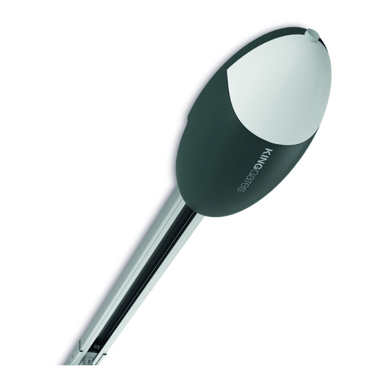
    Telefonnummer +39 0172 1812574 erreicht werden kann. 1.6 - PRODUKTBESCHREIBUNG UND BESTIMMTE VERWENDUNG ELEVO ist ein Getriebemotor zur Automatisierung von Schnitt- und obenliegenden Türen. ELEVO arbeitet mit Elektrizität. Bei einem Stromausfall kann der Getriebemotor entriegelt und die Tür manuell bewegt werden. - 114 -...
  • Seite 117: Technische Eigenschaften

    2 - TECHNISCHE EIGENSCHAFTEN ELEVO620 ELEVO1000 230~ - 50/60 230~ - 50/60 Versorgung (Vac - H) Elektrische Höchstleistung (W) Schnitt <10 / Auf-und-Über-Tür <8,5 Schnitt <16 / Auf-und-Über-Tür <11 Türfläche (m Maximales Hubgewicht der Tür (kg) 1000 Anfahrkraft (N) Höchstgeschwindigkeit (cm/s) -20 ÷...
  • Seite 118: Installationsplan

    2.2 - INSTALLATIONSPLAN BAUTEILE ZUSATZZUBEHÖR Motor Schlüsselwahlschalter Sender Interne Lichtschranke Kettenführung /Riemen Externe Lichtschranke Steuereinheit Blinkleuchte Digitaler Funkwahlschalter Sicherheitsleisten Adapterarm für Kipptore mit Gegengewichtsausgleich KABELLÄNGE < 10 Meter von 10 bis 20 Meter von 20 bis 30 Meter Fotozellen (TX) 2 x 0,5 mm 2 x 0,5 mm 2 x 0,5 mm...
  • Seite 119: Montage

    3 - MONTAGE FIG. 4 Die Installation des Getriebemotors ELEVO umfasst drei Schritte: • Montage der Führungen (siehe Abschnitte 3.2.1 und 3.2.2). • Montage des Getriebemotors an der Führung (siehe Abschnitt 3.2.3). • Montage des Getriebemotors an der Decke (siehe Abschnitt 3.2.4)
  • Seite 120 FIG. 7 FIG. 12 FIG. 8 FIG. 13 FIG. 9 FIG. 10 FIG. 11 - 118 -...
  • Seite 121: Montage Des Getriebemotors An Der Führung

    Abhängigkeit vom Untergrund mit zwei Schrauben, Dübeln oder Nieten sichern. Die Ausgangswelle des Getriebemotors ELEVO an den 3. Die Klammern [H] mit Schrauben [I] und Muttern [L] sichern Führungskopf [A] anschließen und mit 4 Schrauben M6.3x38 [G] und das geeignetste Bohrung auswählen, um den Abstand B...
  • Seite 122 6. Sicherstellen, dass sich die Führung perfekt horizontal 9. Dann die Verbindungsklammer des Torflügels [N] mit Nieten befindet; dann den überschüssigen Teil der Klammern mit oder Schrauben sichern (Abb. 21). Für das Material des einer Säge absägen (Abb. 19). Torflügels geeignete Schrauben oder Nieten verwenden und sicherstellen, dass sie der max.
  • Seite 123: Elektrische Anschlüsse

    3.3 - ELEKTRISCHE ANSCHLÜSSE FIG. 27 1. Die Abdeckung durch Lösen der Schraube (Abb. 24) und Drücken der Taste (Abb. 25) öffnen. 2. Die kleine Scheibe [S] mit einem Schraubenzieher entfernen (Abb. 26). 3. Die Kabel durch die Öffnung [S] führen (Abb. 27). 4.
  • Seite 124: Timer-Funktion

    ACHTUNG! Das zusammen mit ELEVO gelieferte Kabel nie abschneiden oder entfernen. Falls nicht bereits verfügbar, muss eine Steckdose für den Anschluss von ELEVO an die Stromversorgung von einem qualifizierten Elektriker unter Beachtung der 1 - 2 Warnleuchte: 24Vdc max. 15W geltenden Gesetzgebung, Standards und Bestimmungen Fototest: 24 Vdc Ausgang für Test...
  • Seite 125: Haupteigenschaften Der Steuerung

    4 - HAUPTEIGENSCHAFTEN DER • Eingang für externe Antenne zur Vergrößerung der Reichweite der Sender (Abschnitt 10.8). STEUERUNG • Pausenzeiten für automatische erneute Schließung einstellbar zwischen 0 und 180 Sekunden mit Knauf (Abschnitt 4.2). • Befehl automatisierter Zugang für einen Motor 24 V. •...
  • Seite 126: Einstellung Dip-Switch

    4.1 - EINSTELLUNG DIP-SWITCH 4.2 - EINSTELLUNG DES KNAUFS FORCE FUNKTION Leistung: Einstellung der Motorleistung. Durch Drehen Betriebsweise Befehl Schritt bei Schritt: dieses Knaufs in Uhrzeigersinn werden die Leistung und die Öffnen / Stopp / Schließen / Stopp Geschwindigkeit des Motors angehoben. Zur Validierung der ist der Schrittbetrieb aktiviert.
  • Seite 127: Programmierung Der Mit Dem Ausgang "Lock/Aux" Verknüpften Taste

    5.2 - PROGRAMMIERUNG DER MIT DEM 5.5 - LÖSCHEN EINES EINZELNEN SENDERS AUSGANG “LOCK/AUX” VERKNÜPFTEN Diese Operation löscht einen einzelnen Sender aus dem Speicher. TASTE 1. PDIE TASTE RADIO FÜR 4 SEKUNDEN DRÜCKEN UND Dieses Verfahren gestattet die Programmierung der Taste der LOSLASSEN, WENN DIE LED RADIO BLINKT: Die rote LED Funksteuerung, die mit dem Ausgang “Lock/AUX”...
  • Seite 128: Programmierung Der Türbewegung

    6 - PROGRAMMIERUNG 6.2 - ERWEITERTE PROGRAMMIERUNG DER BEWEGUNG DER AUTOMATISIERUNG DER TÜRBEWEGUNG Mit diesem verfahren speichert die Steuerung die Zeiten und die Zum Starten des Systems muss eines der folgenden Leistung ab, die für die Öffnung und die Schließung des Systems Programmierungsverfahren ausgeführt werden: erforderlich sind.
  • Seite 129: Testen Und Inbetriebnahme

    7 - TESTEN UND INBETRIEBNAHME GELBE LED SET: ununterbrochen an oder blinkend, wenn sich die Steuerung in einem Menü Programmierung befindet Nach Abschluss der Programmierung überprüfen: aus, wenn sich die Steuerung nicht in einem Menü • dass die Motoren nach ein paar Sekunden abgeschaltet Programmierung befindet werden, nachdem die Phasen Öffnung oder Schließung abgeschlossen sind (auch die LED “error”...
  • Seite 130: Reset-Verfahren

    9 - RESET-VERFAHREN 10.3 - SICHERHEITSVORRICHTUNGEN KONTAKTE: 4-9-10. Das Resetverfahren Reset löscht die Parameter der Türbewegung Die Steuerung weist weist zwei verfügbare Sicherheitseingänge (Abschnitt 6) und alle erweiterten Funktionen (Abschnitt 11). für spannungsfreie Anschlüsse auf. Es kann im Fall von Programmierungsfehlern ausgeführt werden und es stellt die Steuerungskarte zurück auf die Werkseinstellungen.
  • Seite 131: Stromversorgung 24V Der Zubehörvorrichtungen

    10.6 - STROMVERSORGUNG 24V DER 10.8 - ANTENNE ZUBEHÖRVORRICHTUNGEN KONTAKTE: 13-14. Kontakt Antenne für den Empfang des Signals des Senders. KONTAKTE: 8-5, 10-5. Werksseitig ist ein Kabel an diesen Kontakt angeschlossen. Nominalspannung 24 V , max. 10W, Ausgang für die Zur Erweiterung des Empfangsbereiches kann eine externe Stromversorgung externer Zubehörvorrichtungen wie Fotozellen, Antenne angeschlossen werden...
  • Seite 132: Erweiterte Programmierung

    11 - ERWEITERTE PROGRAMMIERUNG 13 - PROGRAMMIERUNG AUSGANG AUX Die Steuerung weist zusätzliche Spezialfunktionen auf, die für die meisten Standardinstallationen nicht erforderlich sind. Alle Diese Programmierungssequenzen sind für den Betrieb des Beschreibungen folgen hier. Systems unwesentlich, sie gestatten jedoch die Einstellung des Typs (Schloss oder Courtesy Light), der an den Ausgang AUX angeschlossenen Geräte.
  • Seite 133: Auswahl Der Vorrichtung, Die An Den Ausgang "Lock/Aux" Angeschlossen Ist

    13.1 - AUSWAHL DER VORRICHTUNG, 3. START-Taste 1 Sekunde lang drücken: Die rote LED “error” leuchtet fest und die LED “Set” schaltet sich je nach gewählter DIE AN DEN AUSGANG “LOCK/AUX” Funktion ein / aus ANGESCHLOSSEN IST 4. DIE TASTEN SET UND RADIO GLEICHZEITIG DRÜCKEN ODER 10 SEKUNDEN WARTEN, UM DAS VERFAHREN ZU VERLASEN: Default = Elektroschloss Die LEDs kehren zurück zur normalen Betriebskonfigurierung...
  • Seite 134: F.a.q

    15 - F.A.Q Problem Symptome / Ursachen Lösung Die LEDs der Steuerung Keine Stromversorgung der Steuerung Die Stromversorgung überprüfen sind Die Sicherungen sind durchgebrannt. Vor Die Sicherungen ersetzen. Falls die Sicherungen erneut abgeschaltet Eingriffen an den Sicherungen muss die durchbrennen, auf Kurzschlüsse der Stromversorgung, Stromversorgung unterbrochen werden.
  • Seite 135 SPIS TRESCI 1 - WAŻNE UWAGI ............................... 1.1 - INTERWENCJE KONSERWACYJNE ........................1.2 - WSTĘPNE SPRAWDZENIE ORAZ ROZPOZNANIE TYPU, KTÓRY MA BYĆ UŻYWANY ........... 1.3 - UTYLIZACJA ..............................1.4 - POMOC TECHNICZNA ............................1.5 - DEKLARACJA ZGODNOŚCI I DEKLARACJA ZASTOSOWANIA W MASZYNACH ..........1.6 - OPIS PRODUKTU I JEGO PRZEZNACZENIE ......................2 - SPECYFIKACJA TECHNICZNA ...........................
  • Seite 136: Ważne Uwagi

    Czyszczenie powierzchni urządzeń: użyj lekko wilgotnej (nie trybie automatycznym jest niedozwolona. mokrej) szmatki. Nie używaj substancji zawierających alkohol, • Zabrania się stosowania bramy ELEVO w środowisku benzen, rozcieńczalniki lub inne łatwopalne substancje; użycie zapylonym, zasolonym oraz strefach zagrożenia wybuchem. tych substancji może uszkodzić urządzenia i spowodować...
  • Seite 137: Wstępne Sprawdzenie Oraz Rozpoznanie Typu, Który Ma Być Używany

    1.2 - WSTĘPNE SPRAWDZENIE ORAZ ROZPOZNANIE TYPU, KTÓRY MA BYĆ UŻYWANY Należy pamiętać, że urządzenie nie kompensuje usterek spowodowanych niewłaściwym montażem czy nienależytą konserwacją, a zatem przed przystąpieniem do montażu należy upewnić się, że konstrukcja jest odpowiednia oraz że spełnia aktualne normy, a w razie potrzeby dokonać ewentualnych zmian konstrukcyjnych w celu wprowadzenia szczelin bezpieczeństwa oraz zabezpieczenia bądź rozdzielenia wszystkich stref zgniatania, ścinania i przechodzenia, a także potwierdzenia, że: • Brama nadaje się do automatyzacji (sprawdzić instrukcję eksploatacji bramy i wskazówki). Konstrukcja bramy jest sztywna i odpowiednia do zautomatyzowania.
  • Seite 138: Utylizacja

    12:30 i od 14:00 do 18:00. 1.6 - OPIS PRODUKTU I JEGO PRZEZNACZENIE ELEVO to motoreduktor przeznaczony do automatyzacji bram segmentowych i uchylnych. ELEVO działa na energię elektryczną, w przypadku awarii zasilania można odblokować motoreduktor, a bramę przesunąć ręcznie. - 136 -...
  • Seite 139: Specyfikacja Techniczna

    2 - SPECYFIKACJA TECHNICZNA ELEVO620 ELEVO1000 230~ - 50/60 230~ - 50/60 Zasilanie (V - Hz) Maksymalna moc elektryczna (W) Segmentowe <10 / Bramy uchylne <8,5 Segmentowe <16 / Bramy uchylne <11 Powierzchnia bramy (m Maksymalny ciężar podnoszenia drzwi (Kg) 1000 Siła napędowa przy uruch (N) Szybkość maksymalna (cm/s)
  • Seite 140: Rzut Montażowy

    2.2 - RZUT MONTAŻOWY PODZESPOŁY WYPOSAŻENIE DODATKOWE Silnik Przełącznik kluczykowy Nadajnik Fotokomórka wewnętrzna Łańcuch / pas prowadzący Fotokomórka zewnętrzna Centrala sterująca Światło migające Cyfrowy przełącznik radiowy Krawędzie bezpieczeństwa (zabezp. krawędziowe) Wspornik adaptacyjny dla bram z przeciwwagą DŁUGOŚĆ PRZEWODU < 10 metrów od 10 do 20 metrów od 20 do 30 metrów Fotokomórki (TX)
  • Seite 141: Montaż

    3 - MONTAŻ RYS. 4 Instalacja motoreduktora ELEVO składa się z 3 etapów: • Montaż prowadnic (patrz sekcje 3.2.1 i 3.2.2). • Mocowanie motoreduktora do prowadnicy (patrz rozdział 3.2.3). • Montaż siłownika na ścianie (patrz rozdział 3.2.4) 3.2.1 - MONTAŻ PROWADNIC UWAGA: prowadnice do montażu są dostępne tylko dla modelu ELEVO620.
  • Seite 142 RYS. 7 RYS. 12 RYS. 8 RYS. 13 RYS. 9 RYS. 10 RYS. 11 - 140 -...
  • Seite 143: Montaż Siłownika Na Prowadnicy

    3.2.3 - MONTAŻ SIŁOWNIKA NA 2. Po wywierceniu otworów we względnych punktach, pozostawiając motoreduktor na ziemi, podnieś prowadnicę z PROWADNICY przedniej części i zabezpiecz za pomocą dwóch śrub, kołków lub nitów, zgodnie z powierzchnią montażową. Zamontować wał wyjściowy silnika ELEVO na głowicy prowadzącej 3. Przymocuj wsporniki [H] za pomocą śrub [I] i nakrętek [L], [A] i zabezpieczyć za pomocą 4 śrub M6.3x38 [G] (rys. 14). Silnik wybierając otwór najbardziej odpowiedni do zapewnienia przekładniowy obraca się i można go ustawić na trzy różne odległości B, jak pokazano na (rys. 16) sposoby rys.
  • Seite 144 6. Upewnij się, że prowadnica jest idealnie pozioma, a następnie, 9. Następnie przymocuj łącznik [N] za pomocą nitów lub śrub należy odciąć nadmiar sekcji wsporników piłą (rys. 19). (rys. 21). Użyj śrub lub nitów dopasowanych do materiału łącznika i upewnij się, że są w stanie wytrzymać maksymalną siłę potrzebną do otwarcia i zamknięcia łącznika. RYS. 19 10. Poluzować śruby dwóch ograniczników mechanicznych, a następnie przesunąć...
  • Seite 145: Polaczenia Elektryczne

    3.3 - POLACZENIA ELEKTRYCZNE RYS. 27 1. Otwórz pokrywę odkręcając śrubę (rys. 24) i naciskając przycisk (rys. 25). 2. Wyjmij mały krążek [S] za pomocą śrubokręta (rys. 26). 3. Przełóż kable przez otwór (rys. 27). 4. Zobacz rys. 28 i opisy połączeń w tabeli podczas wykonywania połączeń. Jeśli używana jest antena ze światełkiem, odłącz zacisk przewodu (podłączony standardowo do złącza 14) i podłącz ekranowany kabel RG58.
  • Seite 146 1 - 2 Lampa: 24Vdc max. 15W ścisłym przestrzeganiu obowiązujących przepisów, norm i przepisów. ELEVO musi być podłączony do sieci Fototest: 24Vdc wyjscieurzadzenia bezpieczenstwa zasilającej przez wykwalifikowanego elektryka. S2 Photo: Wejście dla urządzeń bezpieczeństwa, Wystarczy włożyć wtyczkę do gniazdka elektrycznego, styk normalnie zamknięty.
  • Seite 147: Główne Cechy Jednostki Sterującej

    4 - GŁÓWNE CECHY JEDNOSTKI • Wejście dla anteny zewnętrznej, która może być użyta do zwiększenia zasięgu nadajników (akapit 10.8). STERUJĄCEJ • Czas przerwy na automatyczne ponowne zamknięcie można ustawić w zakresie od 0 do 180 sekund. za pomocą • Automatyczna Komenda dostępu dla 1 silnika 24V. potencjometru (punkt 4.2). •...
  • Seite 148: Ustawienia Jednostki Sterującej

    4.1 - USTAWIENIA JEDNOSTKI STERUJĄCEJ 4.2 - USTAWIENIA POTENCJOMETRÓW FORCE FUNZIONE Moc: regulacja mocy silnika. Obrót potencjometru w prawo Tryb komend krok po kroku: zwiększa moc i prędkość silnika. Aby zatwierdzić modyfikację, Otwórz / zatrzymaj / zamknij / zatrzymaj należy zaprogramować ścieżkę bramki ponownie. Przy każdym impulsie początkowym (przewodowym lub za pośrednictwem OBSTACLE • nadajnika) jednostka sterująca wykonuje Przeszkoda, wrażliwość na przeszkody: regulacja funkcji akcję. Uruchamia silnik, jeśli system...
  • Seite 149: Programowanie Przycisku Podłączony Do "Lock/Aux

    5.2 - PROGRAMOWANIE PRZYCISKU 5.5 - USUWANIE JEDNEGO ZAKODOWANEGO PODŁĄCZONY DO “LOCK/AUX” PILOTA Ta procedura umożliwia zaprogramowanie przycisku sterowania Ta operacja usuwa pojedynczy nadajnik z pamięci. radiowego połączonego z wyjściem “Lock / AUX” (zaciski 11-12). Aby skorzystać z tej funkcji, wyjście Lock / AUX musi być 1. NACIŚNIJ PRZYCISK RADIO PRZEZ 4 SEKUNDY I ZWOLNIJ JEŚLI ustawione na światło wspomagające - patrz paragraf 13.1. MIGA LED RADIO: Czerwona dioda “radio” miga (jeśli nie, 1. NACIŚNIJ PRZYCISK „RADIO” PRZEZ 1 SEKUNDĘ: Czerwona skonsultuj się Paragraf 14.1) dioda “radio” włącza się w trybie stałym 2. NACIŚNIJ PRZYCISK SET PRZEZ 1 SEKUNDĘ: Czerwona dioda 2.
  • Seite 150: Programowanie Ścieżki

    6. PROGRAMOWANIE ŚCIEŻKI 6.2 - ZAAWANSOWANE PROGRAMOWANIE SIŁOWNIKA Aby uruchomić system, należy wykonać jedną z następujących procedur programowania: Dzięki tej procedurze jednostka sterująca zapamiętuje czasy i moc potrzebną do otwarcia i zamknięcia systemu. • Podstawowe programowanie ruchu automatyki: samodzielne Ponadto procedura ta pozwala na ustawienie punkt początkowy uczenie się...
  • Seite 151: Testowanie I Uruchomienie

    7. TESTOWANIE I URUCHOMIENIE Żółty LED SET: - świeci w trybie stałym lub miga, gdy jednostka sterująca znajduje się w menu programowania Po zakończeniu konfiguracji programowania sprawdź, czy: - gaśnie, gdy centrala znajduje się poza menu programowania • silniki wyłączają się po kilku sekundach od zakończenia fazy otwierania lub zamykania (również dioda LED “ERROR” Czerwony LED START: zgaśnie); jest włączony w trybie ustalonym, gdy jednostka sterująca •...
  • Seite 152: Procedura Resetowania

    9. PROCEDURA RESETOWANIA 10.3 - SPRZĘT OCHRONNY Terminal: 4-9-10. Procedura resetująca usuwa parametry przesuwu drzwi (parametr Jednostka sterująca ma dwa wejścia bezpieczeństwa dostępne dla 6) i wszystkie funkcje zaawansowane (parametr 11). Można go połączeń bez napięciowych (styk bez potencjałowy). wykonać w przypadku błędów programowania i przenosi płytkę sterującą...
  • Seite 153: Akcesoria 24Vdc

    10.6 - AKCESORIA 24VDC Terminal: 8-5, 10-5. Napięcie znamionowe 24V , max. 10W, wyjście do zasilania zewnętrznych akcesoriów takich jak fotokomórki, odbiorniki radiowe itp. Rzeczywiste napięcie wyjściowe może być większe niż wartość nominalna, sprawdzić kompatybilność zewnętrznych akcesoriów. 10.7 - KABLOWE POLACZENIA KONTAKT START Wejście “START” (zaciski 7-8) to normalnie otwarte polecenie aktywacji bramy przez przewód. Metoda aktywacji jest ustawiana za pomocą przełączników DIP 1 i 2 - patrz paragraf 4.1. To wejście jest bez napięciowe (tylko styk bez potencjałowy).
  • Seite 154: Zaawansowane Programowanie

    11. ZAAWANSOWANE 13. PROGRAMOWANIE PROGRAMOWANIE WYJŚCIA AUX Jednostka sterująca ma dodatkowe specjalne funkcje, które nie są Te sekwencje programowania nie są niezbędne do działania wymagane w przypadku większości standardowych instalacji. systemu, ale pozwalają na ustawienie typu (blokada lub Wszystkie opisy są przedstawione poniżej. oświetlenie dodatkowe), wyjściowe urządzeń podłączonych do wyjścia AUX. Aby w dowolnym momencie przerwać...
  • Seite 155: Inne Funkcje

    13.1 - WYBÓR URZĄDZENIA PODŁĄCZONEGO 3. NACIŚNIJ PRZYCISK START PRZEZ 1 SEKUNDĘ: czerwona dioda „błąd” zapala się w trybie stałym, a dioda „Set” włącza DO WYJŚCIA “LOCK/AUX” się / wyłącza zgodnie z wybraną funkcją 4. NACIŚNIJ PRZYCISK SET I RADIO JEDNOCZEŚNIE LUB CZEKAĆ Domyślne = Elektryczna blokada 10 SEKUND, ABY WYJŚĆ PROCEDURĘ: Diody LED powracają do normalnej konfiguracji działaniab Ta procedura pozwala na ustawienie wyjścia “AUX” dla operacji tak jak: W celu przeprowadzenia kontroli urządzeń...
  • Seite 156: F.a.q

    15. F.A.Q Problem Objawy / przyczyna Rozwiązanie Diody LED jednostki sterującej Brak zasilania jednostki sterującej Sprawdź zasilanie sieciowe są wyłączone Przepalone bezpieczniki. Przed Wymień bezpieczniki. Jeśli bezpieczniki ponownie się dotknięciem bezpieczników należy przepalą, sprawdź, czy nie ma zwarcia lub uszkodzeń odłączyć zasilanie. Sprawdź, czy obwodów mocy, kabli, przewodów, akcesoriów, nie ma zwarć lub problemów transformatora i sterownika przed wymianą...
  • Seite 160: Technical Support

    +39 0172 1812574 Technical support More Monday/Friday 8.30-12.30 ; 14-18 (UTC+01:00 time) Dati dell’installatore / Installer details Azienda / Company Timbro / Stamp Località / Address Provincia / Province Recapito telefonico / Tel. Referente / Contact person Dati del costruttore / Manufacturer's details Brand of V2 S.p.A.

Diese Anleitung auch für:

Elevo620Elevo1000

Inhaltsverzeichnis