Balluff BLA0003 Betriebsanleitung
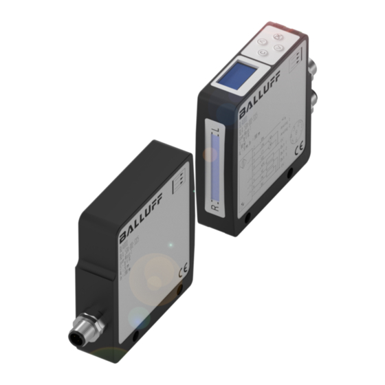
Balluff light array
Inhaltsverzeichnis
Verfügbare Sprachen
Verfügbare Sprachen
Quicklinks
Kapitel
Inhaltsverzeichnis

Verwandte Anleitungen für Balluff BLA0003


Inhaltszusammenfassung für Balluff BLA0003
- Seite 1 BLA 50A-002-S4 Balluff Light Array deutsch Betriebsanleitung english User’s guide...
- Seite 2 www.balluff.com...
- Seite 3 BLA 50A-002-S4 Balluff Light Array Betriebsanleitung deutsch...
- Seite 4 Copyright © Balluff GmbH, Neuhausen a.d.F., Deutschland, 2019. Alle Rechte vorbehalten. Insbesondere: Recht der Vervielfäl- tigung, Veränderung, Verbreitung und Übersetzung in andere Sprachen. Kommerzielle Vervielfältigungen, Reproduktionen, Veränderungen und Verbreitungen jeglicher Form bedürfen der vorherigen schriftlichen Zustimmung durch die Balluff GmbH. Liefermöglichkeiten und technische Änderungen vorbehalten.
-
Seite 5: Inhaltsverzeichnis
BLA 50A-002-S4 BLA 50A-002-S4 Balluff Light Array Benutzerhinweise Über diese Anleitung Aufbau der Anleitung Verwendete Symbole und Konventionen Lieferumfang Laserklasse Zulassungen und Kennzeichnungen Sicherheit Funktionsüberblick Bestimmungsgemäße Verwendung Sicherheitshinweise Bedeutung der Warnhinweise Entsorgung Montage Befestigung Elektrische Anschlüsse Montagetoleranzen Ausrichtung 3.4.1 Ausrichtung ohne Hilfsmittel 3.4.2 Ausrichtung mittels elektronischer Ausrichthilfe... -
Seite 6: Benutzerhinweise
Dieses Gerät ist zertifiziert als Laserklasse 1 gemäß nische Dokumentation für den Sender und den Empfänger DIN EN 60825-1:2008-05. des Balluff Light Array BLA mit IO-Link (BLA 50A-002-S4). Alle Angaben in diesem Bedienungshandbuch, insbeson- Das Lasermodul im Inneren besitzt die Klasse 2 (1 mW dere das Kapitel Sicherheitshinweise müssen unbedingt... -
Seite 7: Sicherheit
BLA 50A-002-S4 BLA 50A-002-S4 Balluff Light Array Sicherheit Funktionsüberblick – Die Geräte sind während des Anschlusses, der Inbe- triebnahme und des Betriebs vor Feuchtigkeit und – Paralleles LASER-Lichtband mit einer aktiven Breite Verunreinigung zu schützen. Insbesondere sind die von 50 mm Ein- und Austrittsfenster für das Lichtband sauber zu... -
Seite 8: Montage
BLA 50A-002-S4 BLA 50A-002-S4 Balluff Light Array Montage Befestigung Aderfarben Funktion Bemerkung braun 15…30 V Montagehinweise weiss (nicht genutzt) – Montieren Sie die Geräte fest an einer stabilen, vibra- blau Masse 0 V tionsfreien Halterung. – Richten Sie die Geräte so aus, dass die Bedienele-... -
Seite 9: Ausrichtung
BLA 50A-002-S4 BLA 50A-002-S4 Balluff Light Array Montage (Fortsetzung) Bild 3-4: Lichtband zu weit rechts Bild 3-5: Lichtband zu tief 3.4.2 Ausrichtung mittels elektronischer Drehwinkel Ausrichthilfe Die korrekte Ausrichtung kann auch elektronisch überprüft werden. Dazu wählen Sie im Hauptmenü Device settings →... -
Seite 10: Bedienung Und Auswahl Der Messmodi
BLA 50A-002-S4 BLA 50A-002-S4 Balluff Light Array Bedienung und Auswahl der Messmodi Einführung Das Gerät wird über 4 Tasten auf dem BLA-Empfänger bedient: Nach dem Einschalten ist das Gerät funktionsbereit und zeigt die aktuellen Messwerte und die gewählten Mess- Beschriftung Funktion modi an. -
Seite 11: Menüstruktur
BLA 50A-002-S4 BLA 50A-002-S4 Balluff Light Array Bedienung und Auswahl der Messmodi (Fortsetzung) Menüstruktur Konfiguration der Analogausgänge Wenn im Display die Messwert-Anzeige sichtbar ist, Beide Analogausgänge können unabhängig voneinander erreicht man durch Drücken der OK (Enter)-Taste das konfiguriert werden. Die Einstellmöglichkeiten sind für Hauptmenü. -
Seite 12: Eine Kante
BLA 50A-002-S4 BLA 50A-002-S4 Balluff Light Array Bedienung und Auswahl der Messmodi (Fortsetzung) Es stehen folgende Modi zur Verfügung: Im Folgenden werden beispielhaft einige Fälle vorgestellt: Mode Kürzel Beschreibung 4.3.1 Eine Kante Left Obj. Für Bahnkantensteuerung. Objekt Um eine von rechts in das Messfeld eingebrachte Kante zu... -
Seite 13: Mehrere Objekte
BLA 50A-002-S4 BLA 50A-002-S4 Balluff Light Array Bedienung und Auswahl der Messmodi (Fortsetzung) 4.3.3 Mehrere Objekte Für den Objektmodus (Object mode) können die gleichen Messmodi wie bei den Analogausgängen gewählt werden. Ein Beispiel mit Anwesenheit von mehreren Objekten: Auswählbare Modi für die Objekteerkennung und -unter-... -
Seite 14: Zählende Modi
BLA 50A-002-S4 BLA 50A-002-S4 Balluff Light Array Bedienung und Auswahl der Messmodi (Fortsetzung) Werte automatisch bestimmen: Unterpunkt Object mode entweder Count Obj. oder Count Slit auszuwählen. Der ausgewählte Modus wird in – Nach Aufruf des Menüpunktes Objects blinkt der der Messwertanzeige unter DO (Digital outputs) mit CO Status des ersten Objektes. -
Seite 15: Display-Optionen
BLA 50A-002-S4 BLA 50A-002-S4 Balluff Light Array Bedienung und Auswahl der Messmodi (Fortsetzung) wird der Überlappungsbereich in der Mitte ausgeblendet. Die Größe des ausgeblendeten Bereichs wird auch in der Messwertanzeige dargestellt. Ausgeblendete Bereiche Ausgeblendete Bereiche Bild 4-11: Blanking aktiv (links: Darstellung bei Messwertanzeige;... -
Seite 16: Normierung Und Livebild
BLA 50A-002-S4 BLA 50A-002-S4 Balluff Light Array Normierung und Livebild Livebild (Monitor) (typ. unter 15 ms). Der Kehrwert der Abtastperiode ent- spricht der Schaltfrequenz. Mit der Livebild-Funktion kann das aktuelle CCD-Signal angezeigt werden. Bild 5-3: Statusinfo-Anzeige Bild 5-1: Livebild mit zwei Objekten im Lichtband... -
Seite 17: Io-Link Schnittstelle
BLA 50A-002-S4 BLA 50A-002-S4 Balluff Light Array IO-Link Schnittstelle IO-Link Daten Datenübertragungsrate COM2 (38,4 kBaud) Mindest-Zykluszeit 4.5 ms Prozessdatenlänge 10 Byte IO-Link Revision Rahmentyp 1.2 / 1.1 Prozessdaten Es werden 10 Byte Prozessdaten übertragen: Nr. Variable Länge (bit) Inhalt UIntegerT... -
Seite 18: Benutzungssperre (Index 0X0C)
BLA 50A-002-S4 BLA 50A-002-S4 Balluff Light Array • IO-Link Schnittstelle (Fortsetzung) Parameterdaten 6.4.1 Identifikationsdaten DPP Index Objektname Länge (Byte) Zugriff Standardwert 0x07 - Vendor ID 888 (0x378) 0x08 (Herstellercode) 0x09 - Device ID 721153 (0xB0101) 0x0B (Gerätecode) SPDU Index SubIndex Objektname Länge (Byte) -
Seite 19: System Command (Index 0X02)
BLA 50A-002-S4 BLA 50A-002-S4 Balluff Light Array • IO-Link Schnittstelle (Fortsetzung) 6.4.3 System command (Index 0x02) Damit können Funktionen wie Signalnormierung und Reset aufgerufen werden. Index 0x02 (Länge 1 Byte) : Wert (Dezimal) Wert (Hex) Funktion 0x82 Rücksetzen auf Werkseinstellung 0xA0 Signalnormierung (vergleiche Kap. - Seite 20 BLA 50A-002-S4 BLA 50A-002-S4 Balluff Light Array • IO-Link Schnittstelle (Fortsetzung) Erklärung der einzelnen Modi (vergleiche Kap. 4.3 für die Analogausgänge und Kap. 4.4 für die Digitalausgänge): Modus Erklärung Modus Erklärung Disable Slit Left Object Object Position Left Slit Slit Position...
-
Seite 21: Technische Daten
BLA 50A-002-S4 BLA 50A-002-S4 Balluff Light Array 67 6 Technische Daten Abmessungen M4 (2x) M4 (2x) (2x) beidseitig (2x) beidseitig (2x) (2x) Abmessungen BLA Sender Bild 7-1: Abmessungen BLA Empfänger Mechanische Daten Elektrische Daten (typisch) Werkstoff Gehäuse Aluminium eloxiert Betriebsspannung Ub 18 bis 30 V DC Werkstoff aktive Fläche... -
Seite 22: Optische Daten (Typisch)
Balluff Light Array 67 6 Technische Daten (Fortsetzung) Optische Daten (typisch) Pflege und Wartung Das Balluff Light Array benötigt, abgesehen von der Reini- Lichtart LASER; Rotlicht 650 nm gung der die Optik schützenden vorderseitigen Oberflä- chen, nur minimale Wartung. Laserklasse Sender- und Empfängerfenster sind frei von Verschmut-...