Balluff BLA 50A-002-S4 Betriebshandbuch
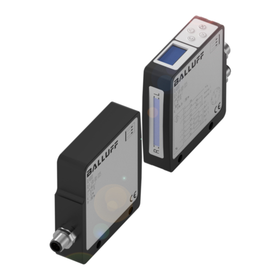
Balluff light array
Inhaltsverzeichnis
Verfügbare Sprachen
Verfügbare Sprachen
Quicklinks
Kapitel
Inhaltsverzeichnis

Verwandte Anleitungen für Balluff BLA 50A-002-S4


Inhaltszusammenfassung für Balluff BLA 50A-002-S4
- Seite 1 BLA 50A-002-S4 Balluff Light Array Betriebsanleitung deutsch...
- Seite 2 Copyright © Balluff GmbH, Neuhausen a.d.F., Deutschland, 2016. Alle Rechte vorbehalten. Insbesondere: Recht der Vervielfäl- tigung, Veränderung, Verbreitung und Übersetzung in andere Sprachen. Kommerzielle Vervielfältigungen, Reproduktionen, Veränderungen und Verbreitungen jeglicher Form bedürfen der vorherigen schriftlichen Zustimmung durch die Balluff GmbH. Liefermöglichkeiten und technische Änderungen vorbehalten.
-
Seite 3: Inhaltsverzeichnis
BLA 50A-002-S4 BLA 50A-001-S115 Balluff Light Array Benutzerhinweise Über diese Anleitung Aufbau der Anleitung Verwendete Symbole und Konventionen Lieferumfang Zulassungen und Kennzeichnungen Sicherheit Funktionsüberblick Bestimmungsgemäße Verwendung Sicherheitshinweise Bedeutung der Warnhinweise Entsorgung Montage Befestigung Elektrische Anschlüsse Montagetoleranzen Ausrichtung 3.4.1 Ausrichtung ohne Hilfsmittel 3.4.2 Ausrichtung mittels elektronischer Ausrichthilfe... -
Seite 4: Benutzerhinweise
Mit dem CE-Zeichen bestätigen wir, dass nische Dokumentation für den Sender und den Empfänger die Geräte den Anforderungen der EG– des Balluff Light Array BLA mit IO-Link (BLA 50A-002-S4). Richtlinien 2004/108/EWG (EMC) und Alle Angaben in diesem Bedienungshandbuch, insbeson- des EMV-Gesetzes entsprechen. -
Seite 5: Sicherheit
BLA 50A-002-S4 BLA 50A-001-S115 Balluff Light Array Sicherheit Funktionsüberblick – Die Geräte sind während des Anschlusses, der Inbe- triebnahme und des Betriebs vor Feuchtigkeit und – Paralleles LASER-Lichtband mit einer aktiven Breite Verunreinigung zu schützen. Insbesondere sind die von 50 mm Ein- und Austrittsfenster für das Lichtband sauber zu... -
Seite 6: Montage
BLA 50A-002-S4 BLA 50A-001-S115 Balluff Light Array Montage Aderfarben Funktion Bemerkung Befestigung braun 15…30 V Montagehinweise weiss (nicht genutzt) – Montieren Sie die Geräte fest an einer stabilen, vibra- blau Masse 0 V tionsfreien Halterung. – Richten Sie die Geräte so aus, dass die Bedienele-... -
Seite 7: Ausrichtung
BLA 50A-002-S4 BLA 50A-001-S115 Balluff Light Array Montage (Fortsetzung) Bild 3-4: Lichtband zu weit rechts Bild 3-5: Lichtband zu tief 3.4.2 Ausrichtung mittels elektronischer Drehwinkel Ausrichthilfe Die korrekte Ausrichtung kann auch elektronisch überprüft werden. Dazu wählen Sie im Hauptmenü Device settings →... -
Seite 8: Bedienung Und Auswahl Der Messmodi
BLA 50A-002-S4 BLA 50A-001-S115 Balluff Light Array Bedienung und Auswahl der Messmodi Einfühung Das Gerät wird über 4 Tasten auf dem BLA-Empfänger bedient: Nach dem Einschalten ist das Gerät funktionsbereit und zeigt die aktuellen Messwerte und die gewählten Mess- Beschriftung Funktion modi an. -
Seite 9: Menüstruktur
BLA 50A-002-S4 BLA 50A-001-S115 Balluff Light Array Bedienung und Auswahl der Messmodi (Fortsetzung) Menüstruktur Konfiguration der Analogausgänge Wenn im Display die Messwert-Anzeige sichtbar ist, Beide Analogausgänge können unabhängig voneinander erreicht man durch Drücken der OK (Enter)-Taste das konfiguriert werden. Die Einstellmöglichkeiten sind für Hauptmenü. -
Seite 10: Eine Kante
BLA 50A-002-S4 BLA 50A-001-S115 Balluff Light Array Bedienung und Auswahl der Messmodi (Fortsetzung) Es stehen folgende Modi zur Verfügung: Im Folgenden werden beispielhaft einige Fälle vorgestellt: Mode Kürzel Beschreibung 4.3.1 Eine Kante Left Obj. Für Bahnkantensteuerung. Objekt Um eine von rechts in das Messfeld eingebrachte Kante zu... -
Seite 11: Mehrere Objekte
BLA 50A-002-S4 BLA 50A-001-S115 Balluff Light Array Bedienung und Auswahl der Messmodi (Fortsetzung) Messmodi wie bei den Analogausgängen gewählt werden. 4.3.3 Mehrere Objekte Auswählbare Modi für die Objekteerkennung und -unter- Ein Beispiel mit Anwesenheit von mehreren Objekten: scheidung sind: Es wird jeweils nur das erste Objekt von rechts und von Left Obj. -
Seite 12: Zählende Modi
BLA 50A-002-S4 BLA 50A-001-S115 Balluff Light Array Bedienung und Auswahl der Messmodi (Fortsetzung) Werte automatisch bestimmen: Unterpunkt Object mode entweder Count Obj. oder Count Slit auszuwählen. Der ausgewählte Modus wird in – Nach Aufruf des Menüpunktes Objects blinkt der der Messwertanzeige unter DO (Digital outputs) mit CO Status des ersten Objektes. -
Seite 13: Display-Optionen
BLA 50A-002-S4 BLA 50A-001-S115 Balluff Light Array Bedienung und Auswahl der Messmodi (Fortsetzung) Falls sich die auszublendenden Bereiche überlappen, so wird der Überlappungsbereich in der Mitte ausgeblendet. Die Größe des ausgeblendeten Bereichs wird auch in der Messwertanzeige dargestellt. Ausgeblendete Bereiche Ausgeblendete Bereiche Bild 4-11: Blanking aktiv (links: Darstellung bei Messwertanzeige;... -
Seite 14: Normierung Und Livebild
BLA 50A-002-S4 BLA 50A-001-S115 Balluff Light Array Normierung und Livebild kunden angezeigt (mögliche Werte: 1,0 ms bis 100 ms). Livebild (Monitor) Dieser Wert wird automatisch bei der Signalnormierung Mit der Livebild-Funktion kann das aktuelle CCD-Signal ermittelt und bleibt gespeichert bis zu einer erneuten angezeigt werden. -
Seite 15: Io-Link Schnitstelle
BLA 50A-002-S4 BLA 50A-001-S115 Balluff Light Array IO-Link Schnittstelle IO-Link Daten Datenübertragungsrate COM2 (38,4 kBaud) Mindest-Zykluszeit 4,5 ms Prozessdatenlänge 10 Byte IO-Link Revision Rahmentyp 1.2 / 1.1 Prozessdaten Es werden 10 Byte Prozessdaten übertragen: - 4 Byte Analogwert 1 (int32) -
Seite 16: Parameterdaten
BLA 50A-002-S4 BLA 50A-001-S115 Balluff Light Array • IO-Link Schnittstelle (Fortsetzung) 6.3.2 Parameterdaten Über die Parameterdaten kann das BLA vollständig konfiguriert werden. a) Auswahl der Ausgangsfunktion Index 0x40 : Sub- Werte- Länge Standard- Index Objektname Bereich Zugriff Erklärung (Byte) wert... - Seite 17 BLA 50A-002-S4 BLA 50A-001-S115 Balluff Light Array • IO-Link Schnittstelle (Fortsetzung) b) Objekte einlernen Index 0x41 : Werte- Länge Standard- Subindex Objektname Bereich Zugriff Erklärung (Byte) wert (dec) Objects Object 1 0 - 486 Objektgröße: 0 - 48,6 mm Object 2 0 - 486 Objektgröße: 0 - 48,6 mm...
-
Seite 18: Technische Daten
BLA 50A-002-S4 BLA 50A-001-S115 Balluff Light Array Technische Daten Abmessungen M4 (2x) M4 (2x) (2x) beidseitig (2x) beidseitig (2x) (2x) Abmessungen BLA Sender Bild 7-1: Abmessungen BLA Empfänger Mechanische Daten Elektrische Daten (typisch) Werkstoff Gehäuse Aluminium eloxiert Betriebsspannung Ub 18 bis 30 V DC Werkstoff aktive Fläche... -
Seite 19: Optische Daten (Typisch)
BLA 50A-002-S4 BLA 50A-001-S115 Balluff Light Array Technische Daten (Fortsetzung) Optische Daten (typisch) Pflege und Wartung Das Balluff Light Array benötigt, abgesehen von der Reini- Lichtart LASER; Rotlicht 650 nm gung der die Optik schützenden vorderseitigen Laserklasse Oberflächen, nur minimale Wartung. - Seite 20 US Service Center CN Service Center Germany Germany China Balluff GmbH Balluff GmbH Balluff Inc. Balluff (Shanghai) trading Co., ltd. Schurwaldstrasse 9 Schurwaldstrasse 9 8125 Holton Drive Room 1006, Pujian Rd. 145. 73765 Neuhausen a.d.F. 73765 Neuhausen a.d.F. Florence, KY 41042 Shanghai, 200127, P.R.