Werbung
Quicklinks
RS 485-Repeater
RS 485 Repeater
Répéteur RS 485
Repetidor RS 485
Repeater RS 485
Product Information/Produktinformation
1
I
IIIa
2
L+ M
PE M5.2
3
4
A1 B1 A1' B1'
IIIb
5
16
ON
12
DP1
10
6
OFF
PG
OP
13
DP2
ON
7
DC 24 V
11
SIEMENS
IV
A2 B2A2' B2'
8
RS485-
6ES7972-
REPEATER
0AA02-0XA0
ON
2
DC 24 V
9
SIEMENS
A2 B2A2' B2'
RS485-
II
REPEATER
2
1
Á
ON
3
A2
(B2)
E Siemens AG 2010
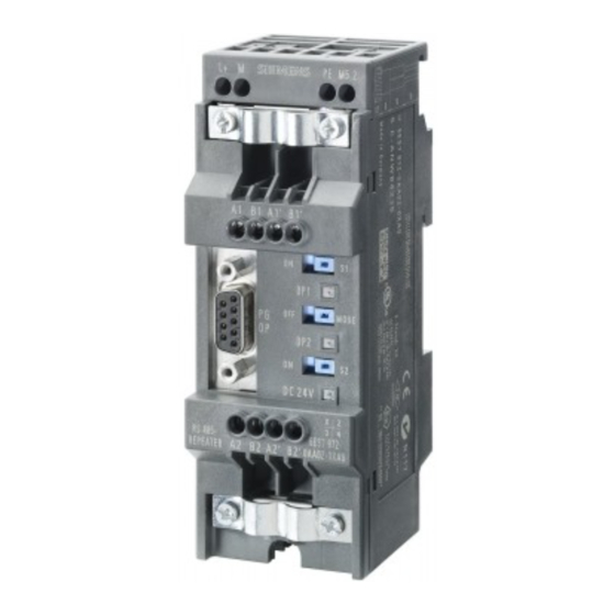
Bild I:
Der RS 485-Repeater dient zur Verstärkung von Bussignalen und zur Kopplung von
Bussegmenten. Die Einstellung der Baudrate erfolgt automatisch.
1
Anschluss für Spannungsversorgung DC 24 V
2
Anschluss für Signalmessungen (im Störfall)
6ES7972-0AA02-0XA0
Schirmschelle
3
Anschluss Bussegment 1
4
Schalter für Abschlusswiderstand Bussegment 1
5
Schalter für Betriebsart OFF
6
Schalter für Abschlusswiderstand Bussegment 2
7
Anschluss Bussegment 2
8
9
Schieber
10
Schnittstelle für PG/OP am Bussegment 1
A5E02926312-01
11
LED 24 V-Spannungsversorgung
12
LED für Bussegment 1
13
LED für Bussegment 2
Bild II:
Der RS 485-Repeater lässt sich auf Normprofilschiene oder auf Profilschiene für S7-300 montie-
8,5
16
10
ren. Bei Montage auf Profilschiene für S7-300 müssen Sie den Schieber auf der Rückseite des
6
RS 485-Repeaters wie folgt entfernen (Bild II):
1. Führen Sie einen Schraubendreher unter den Absatz des Rastelements und
2. bewegen Sie den Schraubendreher zur Baugruppenrückseite. Halten Sie diese Stellung.
3. Bewegen Sie den Schieber nach oben.
Bild III: Kabel abisolieren und Schirmgeflecht umstülpen bei Verwendung von:
–
SIMATIC NET PROFIBUS-Leitung mit Best.-Nr.: 6XV1 830-0AH10, 6XV1 830-3BH10
nach Bild IIIa.
16
10
–
SIMATIC NET PROFIBUS-Leitung mit Best.-Nr.: 6XV1 830-3AH10 nach Bild IIIb.
8,5
6
Bild IV: Beispiel für Bussegment 2: Busanschluss für die erste und letzte Station am PROFIBUS
(Kabel darf nur links angeschlossen werden).
À
"ON" - Abschlusswiderstand zugeschaltet. Der rechte Busanschluss ist abgeschaltet.
Á
Kabelschirm muss blank auf Metallführung liegen
Bild V: Busanschluss für alle weiteren Stationen am PROFIBUS
À
Abschlusswiderstand nicht zugeschaltet. Der rechte und linke Busanschluss sind intern
V
miteinander verbunden.
Á
Kabelschirm muss blank auf Metallführung liegen
À
À
Wichtiger Hinweis
ON
Klemme M 5.2 der Stromversorgung dient als Bezugsmasse für Signalmessungen im Störfall und
DC 24 V
darf nicht verdrahtet werden.
Technische Daten
SIEMENS
Unterstützt taktsynchronen Betrieb
A2 B2A2' B2'
6ES7972-
RS485-
6ES7972-
Spannungsversorgung
0AA02-0XA0
REPEATER
0AA02-0XA0
– Welligkeit (Grenze statisch)
Stromaufnahme bei Nennspannung
– ohne Verbraucher an PG/OP-Buchse
– Verbraucher an PG/OP-Buchse (5 V/90 mA)
Á
– Verbraucher an PG/OP-Buchse (24 V/100 mA)
Baudrate
(wird vom Repeater automatisch erkannt)
OFF
Äquidistanz
– Durchlaufzeit
–
Baudrate: 12 Mbaud
–
Baudrate: 6 Mbaud
A2'
A2
A2'
–
Baudrate: 3 Mbaud
(B2')
(B2)
(B2')
–
Baudrate: 1,5 Mbaud
–
Baudrate < 1,5 Mbaud
– Jitter
Fig. I:
Fig. II:
Fig. III: Strip cable insulation and turn up braided screen when using:
Fig. IV: Example for bus segment 2:
Fig. V: Bus connection for all other stations on the PROFIBUS:
Points carefully
Terminal M 5.2 of the power supply is used as ground reference for signal measurements in the
case of faults and must not be wired.
Technical specification
Supports isochronous mode
ja
Power Supply
DC 24 V
– Ripple (static limit)
DC 20,4 V bis 28,8 V
Power input at rated voltage
– Without consumer at PU/OP port
100 mA
– Consumer at PU/OP port (5 V/90 mA)
130 mA
– Consumer at PU/OP port (24 V/100 mA)
200 mA
Transmission rate
9,6 kBaud, 19,2 kBaud, 45,45 kBaud,
(detected automatically by the repeater)
93,75 kBaud, 187,5 kBaud, 500 kBaud,
1,5 MBaud, 3 MBaud, 6 MBaud, 12 MBaud
Constant bus cycle time
– Repeater throughput time
–
3,0 T
+ 80 ns
BIT
–
2,4 T
+ 80 ns
BIT
–
2,2 T
+ 80 ns
BIT
–
2,1 T
+ 80 ns
BIT
–
0,5 T
+ 100 ns
BIT
– Jitter
1T = 1/48 MHz = 20,83 ns
The RS 485 repeater is used to amplify bus signals and to link bus segments. The transmission
rate is set automatically.
1
Connection for 24 V DC power supply
2
Connection for signal measures (in the case of faults)
3
Shield clamp
4
Connection bus segment 1
5
Switch for terminating resistor bus segment 1
6
Switch for OFF mode
7
Switch for terminating resistor bus segment 2
8
Connection bus segment 2
9
Slide
10
Interface for programmer/operator panel on bus segment 1
11
24 V power supply LED
12
LED for bus segment 1
LED for bus segment 2
13
The RS 485 repeater can be installed on a standard mounting rail or on a mounting rail for
S7-300. For installation on an S7-300 rail, remove the slide at the rear of the RS 485 repeater
as follows (Fig. II):
1. Insert a screwdriver under the recess in the latching element and
2. Move the screwdriver towards the rear of the module and keep it in this.
3. Push the slide up.
–
SIMATIC NET PROFIBUS cable, Order No.: 6XV1 830-0AH10, 6XV1 830-3BH10 (Fig. IIIa).
–
SIMATIC NET PROFIBUS cable, Order No.: 6XV1 830-3AH10 (Fig. IIIb).
Bus connection for the first and the last station on the SIMATIC NET PROFIBUS cable.
(Cable can only be connected on the left).
À
"ON" - terminating resistor connected. The bus connection on the right is off.
Á
Bare cable shielding must contact the metal guide.
À
The bus connections on the left and right are connected to each other internally.
Á
Bare cable shielding must contact the metal guide
yes
24 V DC
20.4 V DC to 28.8 V DC
100 mA
130 mA
200 mA
9.6 kbps, 19.2 kbps, 45.45 kbps,
93.75 kbps, 187.5 kbps, 500 kbps,
1.5 Mbps, 3 Mbps, 6 Mbps 12 Mbps
3,0 T
+ 80 ns
Baud rate: 12 Mbaud
BIT
2,4 T
+ 80 ns
Baud rate: 6 Mbaud
BIT
2,2 T
+ 80 ns
Baud rate: 3 Mbaud
BIT
2,1 T
+ 80 ns
Baud rate: 1.5 Mbaud
BIT
Baud rate < 1.5Mbaud
0,5 T
+ 100 ns
BIT
1T = 1/48 MHz = 20,83 ns
Werbung

Verwandte Anleitungen für Siemens 6ES7972-0AA02-0XA0


Inhaltszusammenfassung für Siemens 6ES7972-0AA02-0XA0
- Seite 1 Baud rate < 1.5Mbaud 0,5 T + 100 ns 0,5 T + 100 ns – Baudrate < 1,5 Mbaud E Siemens AG 2010 – Jitter 1T = 1/48 MHz = 20,83 ns – Jitter 1T = 1/48 MHz = 20,83 ns...
- Seite 2 Fig. I: Le répéteur RS 485 sert à amplifier les signaux sur le bus et à relier des segments de bus. Le Fig. I: El repetidor RS 485 sirve para amplificar las señales por el bus y para interconectar segmen- Fig.